Harnisch+Rieth D-LE 255 S User manual

Maschinenbau
Werkzeuge
Laborgeräte
2 D-LE 255 S/D - 18.07.14 / Vers.: 1
51
/sL
2
L / s
/
D-LE 255 S
10
60
Air
Manual
Auto
MF
m02
1
5
s
4
Operating instructions
Designation of the machine Single/Double-workplace extraction unit
Machine type: D-LE 255 S / D
Machine no.: ...........................
Keep for future reference!
Home address
Harnisch+Rieth
GmbH & Co. KG
Küferstr. 14 - 16
D-73650 Winterbach
Telephone
+49 7181 / 96 78-0
Fax
+49 7181 / 7 31 39
+49 7181 / 96 78-17
E-mail:
http://www.hr-dental.de

Maschinenbau
Werkzeuge
Laborgeräte
Dear customer:
Thank you for the confidence you have placed in us by purchasing the extraction unit D-LE
255 S/D.
To ensure this device provides you with long years of perfect service, please take the time
to carefully read these operating instructions, especially before first use.
Table of contents
1 Safety................................................................................................................................. 3
1.1 Correct use .............................................................................................................. 3
1.2 Possible dangers ................................................................................................... 3
1.3 Approved operators .............................................................................................. 3
1.4 Safety measures at site of operation................................................................ 3
1.5 Marking of safety references contained in these instructions .................. 4
2 Starting up ....................................................................................................................... 4
2.1 Technical data ........................................................................................................ 4
2.2 Unpacking the single/double-workplace extraction unit............................. 5
2.3 Short description of the unit and component identification ...................... 5
2.4 Starting up procedure........................................................................................... 7
2.4.1 Pneumatic structure of tube/hose installation.................................... 7
2.4.2 Structure of the electrical installation ................................................... 9
3 Operation........................................................................................................................ 10
3.1 Checking the filter system................................................................................. 10
3.2 Variants of the dust-generating device automatic detection. .................. 10
3.3 Automatic On-Off / Connection of dust-generating devices .................... 11
3.4 Automatic air volume control ........................................................................... 11
3.5 Automatic shut-off and filter change control Iamp ..................................... 11
3.6 Self test / initialization ........................................................................................ 12
3.7 Notes to monitoring the airflow volume ........................................................ 12
3.8 Setting the extraction unit parameters........................................................... 13
3.8.1 Manual mode (Manual) ............................................................................ 13
3.8.2 Automatic mode (Auto)........................................................................... 13
4 Error messages ............................................................................................................ 14
5 User menu...................................................................................................................... 15
5.1 Changing the user menu settings ................................................................... 16
5.2 Display - Messages and meanings.................................................................. 17
5.2.1 Display messages for "air volume" (l/s) control variant ................ 17
5.2.2 Display messages for "air velocity" (m/s) control variant ............. 18
6 Cleaning / Maintenance .............................................................................................. 20
6.1 Replacing the filter bag ...................................................................................... 20
6.2 Inserting the filter bag ........................................................................................ 20
6.3 Cleaning (replacement) of ultra-fine filter...................................................... 21
7 Electrical fusing............................................................................................................ 22
8 Settings (short summary) and factory setting values ........................................ 23
9 Warranty conditions .................................................................................................... 24
10 EC Declaration of Conformity ................................................................................... 25

Maschinenbau
Werkzeuge
Laborgeräte
2 D-LE 255 S/D - 18.07.14 / Vers.: 1
1 Safety
1.1 Correct use
The single/double-workplace extraction unit D-LE 255 S is used in dental laboratories for extracting
dust (primarily gypsum dust, mineral dust, plastic dust, metal dust, oxide and other ceramic dusts)
produced when working on dust-producing equipment. It should never be used for vacuuming liquids.
If released dust produces also poisonous gases such as methyl methacrylates, appropriate activated
carbon filters must be placed downstream (e.g., D-AK10 from Harniscn & Rieth).
The extraction unit is fitted with a dust grade M filter (<0.1% maximum permeability) pursuant to DIN
EN 60335.
Unauthorised modifications and changes are not permitted for safety reasons.
The operating and maintenance conditions specified in these operating instructions must be ob-
served at all times.
Caution
The unit is not designed as a medical device.
Use on people is not permitted.
1.2 Possible dangers
-Potential sources of ignition or combustible gases, vapours and liquids should not be extracted with
the unit.
-Switch off the unit and disconnect from mains power supply before carrying out maintenance and
cleaning work (pull out the mains plug).
-Particular attention should be paid to ensuring that the filter bag and ultra-fine filter are always in-
stalled correctly and undamaged, as the dust collected poses a health hazard to a certain extent.
-The unit should be disconnected from the mains power supply before accessing built-in electrical
components.
1.3 Approved operators
The operator of the unit should ensure that the operating instructions are accessible to the operating
personnel and have been read and fully understood. Only then should the operator commission the
unit.
1.4 Safety measures at site of operation
Air flowing out of the air outlet should not be hindered in any way.
The distance between the air outlet and the next obstacle (e.g. a wall or furniture) must be at least 10
cm.
The unit should only be operated in cabinets or confined spaces if adequate ventilation is provided.
The permissible ambient temperature must neither fall below 0 °C nor exceed 40°
°°
°C at 50% relative
humidity.
No foreign bodies should be inserted through the ventilation ducts on the unit.
Danger The unit is not suitable for use in rooms where special conditions exist (e.g., corrosive or explo-
sive atmosphere).

Maschinenbau
Werkzeuge
Laborgeräte
1.5 Marking of safety references contained in these instructions
Note Refers to tips and other particularly useful information.
Caution
Refers to particular methods of operation or handling, non-adherence to which can lead to mal-
functioning, damage or other problems.
Danger
Refers to dangerous situations which can Iead to injuries
2 Starting up
2.1 Technical data
40 330
402
542,7
380
L s/
Manual
Auto
3 0
Ls
/
/0 sm
12
MF
Air
60
10
2
D-LE 255 S
51
50
Illustration 1 Extraction unit dimensions
Designation of the machine : Single/double-workplace extraction unit
Machine type: : D-LE 255 S/D
Unit dimensions : Width 420 mm (with power cord strain relief)
:Depth 390 mm (with extraction sockets)
:Height 542 mm
Electrical connection : 200-240 volt (50 Hz)
Over-voltage category: : II
Power consumption : Max. 1,100 watts (blower power)
Electrical fusing : 2x 16 A/T (mains connection)
Airflow :Max. 55 l/s
Sound pressure :52 dB (A) at min. air volume
:64 dB (A) at max. air volume
Ultra-fine filter quality :Dust grade M, DIN EN 60335-2-69
Filter area :1.4 m2
Specific panel filter load :143 m3/m2 x h
Extraction hose connection :50 mm diameter
Dust absorption :Up to approx. 10 kg (dust type dependent)
Weight : About 25 kg

Maschinenbau
Werkzeuge
Laborgeräte
2 D-LE 255 S/D - 18.07.14 / Vers.: 1
2.2 Unpacking the single/double-workplace extraction unit
1. Place the carton on a flat surface.
2. Remove the top packaging material.
3. Push the packaging material away from the unit. Grasp hold of the unit by the lower edge.
4. The unit (weight = approx. 25 kg) should be lifted out of the carton by two persons.
5. Check the accessories:
•Documentation
•Main power cable Item no. 35028
•Ø 50mm extraction hose, 2m long with two Ø 50 mm connectors, Ø 50 mm extraction hose, 2m
long, Item no. 72050 Ø 50 mm connector, Item No. 72050 ....................................................
•See the delivery note for further accessories
2.3 Short description of the unit and component identification
The single/double-workplace extraction unit D-LE 255 S/D has a powerful high-pressure fan which is
fitted with noise suppression. The unit provides two ways to set the airflow rate indicated for
the detection device (extraction mouth):
-Gradually, by means of a pushbutton.
-Continuously, by means of a potentiometer.
In both cases, the airflow rate is automatically controlled. Thus, the airflow volume at the extraction
funnel remains constant regardless of the contamination degree of the filter medium.
It is also equipped with an automatic electronic ignition, an automatic shut-off feature with filter
change indicator, and automatic air volume control. Pneumatic stop valves (accessory) are con-
nected and automatically actuated when the respective dust-generating device is activated, enabling
free airflow at the specified vacuum duct.
The automatic ignition electronics detect a rotating hand-held piece in a fraction of a second and im-
mediately actuate dust extraction. The connected stop valve (accessory) automatically enables the
extraction line immediately. Any commercially-available hand-held pieces can be used for this pur-
pose. The D-LE 255 S/D is also used as an extractor for sand blasting instruments, saws and other
dust-generating devices, electronic detection functioning here in the same manner.
The existing flow control device not only monitors the airflow but also the contamination degree of the
pre-filter and ultra-fine filter. Visual and acoustic indicators are provided to indicate the condition of fil-
ter components, as well as the decrease of the exhausted airflow volume at the extraction funnel be-
low a specified minimum value. If the airflow volume falls below the minimum, all dust-generating de-
vices connected to the extraction unit are shut down.
At specific time intervals but only after switch-on, the extraction unit performs a self-test and clears
the lines.
The extraction unit is designed for mains voltages of 200 - 240 (± 10%) V. That is, the air volume set
by the potentiometer is held constant regardless of line voltage fluctuations.
The dust is collected in a double-ply disposable filter bag with a capacity of up to 10 kg, depending on
the nature of the dust.
The ultra-fine filter has a large surface area and is serially connected to the disposable filter bag, has
a maximum transmittance of <0.1%.

Maschinenbau
Werkzeuge
Laborgeräte
380
51
/s
L
2
L / s
/
D-LE 255 S
10
60
Air Manual
Auto
MF
m02
1
5
s
4
1
2
2
3
1
4
3
7
8
9
21
6
5
13
19
A2
C2
46
A1
C1
12
34 35
Fig. 2: Front and left side view
25
30
32
31
28
26
27
11
15
16
10
17
25
24
23
22
20
12
21
29
33
3 Unit cross-section viewed from the left
1Housing
2Cover
32x Quick-action closure
4Panel
5Mounting cover
62x knurled-head screws
7
Socket for automatic stop
valve B1
8Socket f
or automatic stop
valve B2
9
Socket to activate extraction
unit via external voltage 9-
30V DC
13
Connector plug(230 V/50
Hz)
19 Fuse compartment
21 Ball rollers

Maschinenbau
Werkzeuge
Laborgeräte
2 D-LE 255 S/D - 18.07.14 / Vers.: 1
10
Plastic connection for filter bag 24
Sealing surfaces, all-round
11
Filter bag 25
Seal, all-round
12
Mesh basket 26
Extraction channel
15
Ø 63 mm-nozzle (inside) 27
Extraction chamber
16
Ø 50 mm nozzle (outside) 28
2x M6 nuts
17
Closure cover for filter bag 29
Slotted retaining strips
20
Pre-filter 30
Electric cabinet
22
9x screws for floor space 31
Ultra-fine filter
23
Vacuum motor (fan) 32
Ultra-fine filter chamber
33
Main control board
2.4 Starting up procedure
-Check the filter system (see Section "3.1 Checking the filter system").
2.4.1 Pneumatic structure of tube/hose installation
(See Fig. 4, page 7)
1. Establish a hose/tube connection to the dust-generating devices (select a hose length which is a
short as possible, maximum length approx. 2 m for each device), see Fig. 4, page 7.
2. The hose/tube installation can be connected to 50 mm nozzles (16) (Fig. 3, page 5) of the exhaust air
fitting.
3. Connect the automatic pneumatic stop valve to the compressed air supply (pneumatic connection
(41), see Fig.5, Page 8).
Note All devices and installation components can be connected to the unit with flexible hoses or rigid
plastic tubes (see following examples).

Maschinenbau
Werkzeuge
Laborgeräte
1
12a
10a
2
12a
1
0
a
37
37
1a 3a
6a3a
3a
7a7a
4a2a
4a
11a
11a
Absaugung
3a
5a
9a
9a
1
2
Absaugung
Ø
50
Y-Stück: Ø 50 / Ø 50
Fig. 4 Laying tubing to devices over long distances
1a
90 °angle piece Ø 50 7a Y-piece connection fitting Ø 50
2a
Angle connection fitting Ø 50 9a Reducer Ø 50 / Ø 45 / Ø 40
3a
PVC hose fitting Ø 50 10a
PVC hose fitting Ø 50 / Ø 45 / Ø 40
4a
Hose/Tube Ø 50 11a
Hose/Tube Ø 50 / Ø 45 / Ø 40
5a
Y-piece Ø 50 12a
PVC hose fitting Ø 50 / Ø 45 / Ø 40
6a
Y-piece connection fitting Ø 50 37 Automatic pneumatic stop valve
1
Dust-generating device no. 1 33 Main board, see Fig. 2
2
Dust-generating device no. 1

Maschinenbau
Werkzeuge
Laborgeräte
2 D-LE 255 S/D - 18.07.14 / Vers.: 1
2.4.2 Structure of the electrical installation
1. Connect the dust-generating device mains power cable to socket A1 and A2 (see Fig. 5, Page 8).
2. Connect the stop valve connection cable to socket B1 and B2. Turn the
outer sleeve (39) of the connector (38) to the right to lock the connector in socket B1 and
B2 (bayonet lock).
3. Establish a connection to the mains power supply (230V/50Hz) with the mains cable provided (socket
(13)).
L/
D-LE 255 S
2
Air
60
MF
2
/m
0s
1
30
51
s
L s/
Auto
Manual
10
B1
B2
2
1
2
1
2
1
39 40 41 37
38
47
3
4
3
5
C2
C1
D
A1
A2
13
19
9
23
22
Fig.5 Unit and electrical connections
9Socket to activate extraction unit
via external voltage 9-30V DC
39 Outer connector sleeve with bayonet lock
13 Mains socket 230V/50Hz 40 Solenoid valve
19 Main fuses (2x 16 A / T) 41 Pneumatic connection
16 Connection fittings Ø 50 mm (Fig. 3, Page 5) 47 Pressure reducing valve
37 Automatic pneumatic stop valve A1 1x socket for dust-generating devices 230 V
38 Connector with cable and solenoid valve socket A2 1x socket for dust-generating devices 230 V
B1
Stop valve socket no. 1, 230 V, AC B2 Stop valve socket No. 2, 230 V, AC
C1
1x socket for special control cable to
activate the exhaust air fitting.
C2 1x socket for
special control cable to activate
the exhaust air fitting.
1Stop valve No. 1 2Stop valve No. 2
DSpecial connection (e.g., milling unit)
4. Activate the main switch (34) (control lamp (35) illuminates green).
5. The "Auto" (22) or "Manual" button (23) illuminates green (the last operated button illuminates).
6. After pressing the "Manual" button (23) (illuminates green), the extraction unit enters continu-
ous operation mode.

Maschinenbau
Werkzeuge
Laborgeräte
/sL
s5
0
3
L1
/ s
20m
Auto
MF
Manual
10
60
Air
D-LE 255 S
/
12
35
37
38
39
40
22
23
4
6
4
2
4
1
4
4
4
3
4
5
36
34
Fig. 6 Panel with control elements
34 Main switch 37 "Ready" control lamp
35 Main switch control lamp (green) 38 "Service" control lamp
36 Air volume controller (potentiometer) 39 "Filter change" control lamp for ultra-fine filter
40 "Filter change" control lamp for pre-filter
3 Operation
3.1 Checking the filter system
(See Fig. 2 and 3, Page 5)
Caution The single/double-workplace extraction unit D-LE 255 S/D must only be operated with a cor-
rectly fitted, undamaged ultra-fine filter (31) and filter bag (11).
1. Open the 2x quick-action closures (3) and remove cover (2).
2. Ensure that the ultra-fine filter (31) is not damaged and is pressed tightly against the retaining
strips (29) on the seal surfaces (24).
3. The two M6 nuts (28) should be tightened firmly and evenly.
4. The assembly cover (5) must be screwed tight with two knurled-head screws (6).
5. The filter bag (11) should be undamaged when inserted in the wire basket (16), see Fig.17, Page
19.
6. The plastic connector (10) must sit tightly on the connection fitting (15).
7. Clamp the cover (2) firmly with the aid of the two quick-action closures (3)
3.2 Variants of the dust-generating device automatic detection.
(See Figure 5 and 6, Page 8 and 9)
1. Extraction unit activation via sockets A1 and A2.
a) Connect the dust-generating device(s) to socket A1 and/or A2.

Maschinenbau
Werkzeuge
Laborgeräte
2 D-LE 255 S/D - 18.07.14 / Vers.: 1
b) Press and hold the "m" button (45) for 5 sec. Ensure that any connected dust-generating de-
vices are in standby mode.
c) Measurements are performed every 10 seconds (shown on display). After completing the
measurements, the extraction unit is ready for operation.
2. Activation of the extraction unit via special control cable (potential-free contacts).
a) Connect the dust-generation device to socket C1 and/or C2 of the extraction unit by means of
a special control cable. The cable (option) can be provided by H+R.
3. Activation of the extraction unit via socket 9.
a) The extraction unit will be activated by applying a 9-30V DC voltage to socket 9.
3.3 Automatic On-Off / Connection of dust-generating devices
The extraction unit is equipped with an electronic On-Off actuator, which reacts to most hand-held
pieces and other dust-generating laboratory devices.
Caution The power input (power consumption) of devices to be connected should not exceed 900 Watt
per socket A (A1, A2). The overall power input value of all connected devices should, in total,
not exceed1800 W.
1. Connect the dust-generating devices to sockets A1 and A2 (230 V, AC).
2. Connect the automatic stop valves accordingly to sockets B1 and B2 (230 V, AC).
3. The "Auto" button illuminates green after the unit is switched on (main switch (34) ON) (see Fig.
6, Page 9).
Note Please contact our H+R Customer Service Dept. (tel.: +7181/9678-0) if devices other than those
we have intended are to be connected.
The extraction unit starts automatically as soon as a connected dust-generating device is acti-
vated. The unit stops after a delay of approx. 8 seconds if all connected devices are deacti-
vated.
It is possible to adapt the unit individually if it does not react to a particular dust-
generating device. Please contact the H+R Customer Service Dept. to that end.
3.4 Automatic air volume control
The air volume is increased or decreased to suit the number of dust-generating devices in operation
and is independent of the filter contamination degree. The set air volume is then maintained at a con-
stant level by electronic control until the automatic shut-off feature is triggered. The air volume can be
altered by pressing button (43) (to reduce the volume) or button (42) (to increase the volume), see
Fig.6, Page 9.
3.5 Automatic shut-off and filter change control Iamp
(See Fig.6, Page 9)
Note An underpressure sensor triggers the automatic shut-off feature and the "filter change" control
Iamp (39 or 40) illuminates as soon as the max. permissible filter bag (11) (see Fig.3, Page
5) filling level is reached. The extraction unit and the connected dust-generating devices are
switched off.
1. The filter bag (11) must be replaced (see Section "6.1 Replacing the filter bag").
Note The extraction unit can be switched on and off again or the filter bag (11) lightly beaten if the
automatic shut-off feature deactivates the unit. The unit can then operate for some time without

Maschinenbau
Werkzeuge
Laborgeräte
changing the filter bag.
2. Open the clamp closure (3) and remove the closure cover (2) to lightly beat the filter bag (11).
Note •The ultra-fine filter should be replaced if the filter change Iamp (39) illuminates after
the automatic shut-off feature is triggered. See Section "6.3 Cleaning (replacement) of the
ultra-fine filter".
•The pre-filter should be replaced if the filter change Iamp (40) illuminates after the auto-
matic shut-off feature is triggered. See Section "6.1 Replacing the filter bag".
3.6 Self test / initialization
(See Fig.6, Page 9)
A self-test is automatically executed (without user intervention) to avoid the clogging of
pipes/connecting hoses and ensure that the prescribed air volume is available at all extraction ducts.
Every time the device is switched on, the software automatically verifies whether the selected initiali-
sation interval has been exceeded. If so (factory setting: 5 hours), the self-test is started immediately
(but only after the unit is re-started).
Note The self-test can also be performed on demand by holding down the "Manual" button; the unit
is switched on via the main switch.
During the initialisation phase, all extraction ducts are individually open and vacuumed at full extrac-
tion power for 10 seconds. In that period, we total vacuum in the ultra-fine filter chamber is measured
and displayed.
If the total vacuum in the ultra-fine filter chambers exceeds the allowable value set in the service
menu, the extraction unit is switched off with a fault display.
Note If, after initialisation, allowable parameter values are not held, this is indicated by a flashing of
all LEDs (2x red, yellow, green), accompanied by a periodic beep.
I n i t i a l i s i e r u n g
0 2 9 9 8
1
2
A) Test of channel no. 1.
The pressure drop is displayed con-
tinuously
I n i t i a l i s i e r u n g
0 3 0 0 4 0 K
20155
1
2
B) Test of channel no.2
Pressure loss in channel
no. 1 does not exceed the allowable
value thus the display shows "OK".
Channel No. 1 remains open.
I n i t i a l i s i e r u n g
0 3 0 0 4 0 K
2 0 1 5 5 F e h l e r
1
2
C) End of the self-test
Extraction unit is turned off as a
result of an error.
Pressure loss in channel
no. 2 exceeds the allowable value thus
"Error" is displayed.
Fig. 7 Self-test procedure
3.7 Notes to monitoring the airflow volume
A warning is issued 10 seconds after the airflow volume falls below the setpoint by 5%.
In this case, the yellow service LED (38) and both red filter change LEDs (39 and 40) flash and
the buzzer sounds intermittently.
Caution If the air flow volume falls below the setpoint for over 60 seconds, the extraction unit is
switched off (see Error No. 4 in the "Error messages" table on page 13)

Maschinenbau
Werkzeuge
Laborgeräte
2 D-LE 255 S/D - 18.07.14 / Vers.: 1
Note Every time you switch on the extraction unit, the airflow volume control remains off
for approximately 30 seconds
3.8 Setting the extraction unit parameters
The extraction unit can be operated under two sets of rules:
-Control variant "Air volume"(L/s)
-Control variant "Air speed" (m/s)
Users can toggle between modes by pressing and holding the "Air "(41) button for five seconds.
Furthermore, the extraction unit can operate in two modes:
•Automatic mode "Auto"
•Manual mode "Manual"
3.8.1 Manual mode (Manual)
In manual mode, the extraction unit can only be operated under the "air volume" (L/s) control variant.
In this mode, all available extraction channels are open.
Note Any unnecessary channels can be disabled via the user menu.
sL /
Manual
Auto
/s
L
0
3
/ s
0m
2
1
MF
10
60
Air
2
D-LE 255 S
15
20
3
5
37
38
39
40
22
23
46
42
41
44
43
45
3
6
23a
41a
Fig.8 Panel in manual mode
After pressing the "Manual" button, the LED (23a) illuminates green. Thus, the extraction unit is put
into operation immediately. In manual mode, the "Air" (41a) button LED illuminates as the extraction
unit necessarily adopts the "air volume" (l/s) control variant.
Set the desired air volume with the controller (36). The set air volume is shown on the display. Air
volume is automatically regulated and remains constant regardless of the filter contamination degree.
Note The controller (36) can be used to set the air volume of the fan from 10 l/s up to its maximum
value.
3.8.2 Automatic mode (Auto)
In automatic mode, the extraction unit can be operated under two control variants: "Air volume" (l/
s) and "Air speed" (m/s)

Maschinenbau
Werkzeuge
Laborgeräte
sL /
Manual
Auto
/sL
0
3
m/ s
0
2
1
MF
10
60
Air
2
D-LE 255 S
15
20 35
37
38
40
22
23
46
42
41
44
43
45
36
23a
41a
22a
39
Fig. 9 Panel in automatic mode
The LED (22a) illuminates green after pressing the "Auto" button (22). In this mode, the extraction
unit is only switched on as the connected external dust-generating device is activated. In automatic
mode, the "Air" (41a) button LED will only illuminate if the "Air volume" (l/s) control variant
is selected. The "Air" (41a) button LED dims if the control variant "Air speed" (m/s) is selected.
Note Users can toggle between control variants, i.e. "Air volume" (l / s) or "Air speed" (M / s) , at
will by pressing and holding the "Air" (41) button for 5 seconds.
The total airflow volume (setpoint) in all detection points (extraction funnels) is calculated as the
product of the set airflow volume (l/s control variant) and air speed (m/s control variant) by the num-
ber of open extraction channels.
Extraction channels are automatically opened or closed via the operating dust-generating de-
vice by means of downstream stop valves.
Note Use the buttons "+" and "-" or the "User menu" to regulate the l/s air basis from 10 l/s to 55 l/s.
4 Error messages
Error
number Error type
LED (37)
Opera-
tion
LED (38)
Service
LED (40)
Pre-filter
LED (39)
Ultra-
fine filter
Buzzer
1. Replace pre-filter
2. Replace ultra-fine filter
3. Excessive total vacuum
(In the ultra-fine filter cham-
ber)
4.
Minimum airflow volume is
below (by> 5%)
A warning
signal is issued
after 10 sec.
The extraction unit
is switched off after
one minute.
5. Offset pressure sensors NIO
6. Value of the airflow sensor
NIO

Maschinenbau
Werkzeuge
Laborgeräte
2 D-LE 255 S/D - 18.07.14 / Vers.: 1
7. Interruption in electrical cir-
cuit of the motor
Fault on the phase-angle control (overcur-
rent or no zero crossings)
8. Error communicating with
phase-angle control
9. Error in EEPROM memory
10. Error during initialisation
The extraction
unit is switched off.
After correcting the
error, switch on and
reset the extraction
unit.
11.
The desired level air-
flow volume exceeds max.
air volume value of the
blower, for example, by con-
necting an additional chan-
nel.
1
1m/ s
3 0
L / s
3 5 L / s
12
Example: Air volume for extraction channel
(1st workplace) is set to 35 l/s. After activating
the 2nd extraction channel (2nd workplace), air
volume demands stands at 70 l/s. This ex-
ceeds the fan power by 15 l/s In this case, the
extraction channel 2 is disabled immediately
and shown in black on the display after 10
seconds.
Beep sounds and
display shows
this message: In-
sufficient air vol-
ume for additional
channel. The addi-
tional extraction
channel is shown
black on the display
after 10 seconds.
The extraction
channel and socket
A1 and A2 are im-
mediately blocked
or de-energized.
- No signal,- Continuous signal, - Periodic Signal
(with LEDs and buzzer)
5 User menu
(See Fig.6 Page 9)
The user menu allows adjusting the operating parameters and areas of the extraction unit.
Note The user menu is activated by pressing and holding the "MF" (46) button for 5 seconds.
The user menu is exited by pressing the "MF" (46) button.
User menu settings
Parameter name Area/Range Delivery value
1.
Air basis (l/s) 10 to 60 L/s in 5l increments 20 l/s
2.
Current threshold 1 0 to 255 215
3.
Current threshold 2 0 to 255 215
4.
Extraction channel 1 / Enable or
disable
or X
5.
Extraction channel 2 / Enable or
disable
or X

Maschinenbau
Werkzeuge
Laborgeräte
6.
Hose/tube diameter 1 40, 45, 50, 60 mm 40 mm
7.
Hose/tube diameter 2 40, 45, 50, 60 mm 40 mm
8.
Air basis (m / s) 15 to 50 m/s 20 m/s
9.
Language De, En, Fr, Es De
10.
Sensitivity 255 100
A n we n d e r me n ü
L u f t b a s i s ( L / s ) : 2 0 L / s
F r e i g a b e 1 :
R o h r 1 : 4 0 mm
L u f t b a s i s ( m/ s ) : 2 0 m/ s
E mp f . 1 : ( 1 5 3 ) . 1 0 0
A b s t a n d l i n k s 1 : 0 4 0
S p r a c h e D e
A) User menu
The user menu of the single-
workplace extraction unit consists
of only one page.
A n w e n d e r me n ü 1 / 2
L u f t b a s i s ( L / s ) : 2 0 L / s
F r e i g a b e 1 :
F r e i g a b e 2 :
R o h r 1 : 4 0 mm
R o h r 2 : 4 5 mm
L u f t b a s i s ( m/ s ) : 2 0 m/ s
E mp f . 1 : ( 1 5 3 ) . 1 0 0
A) User menu Page 1
A n w e n d e r me n ü 2 / 2
A b s t a n d l i n k s 1 : 0 4 0
E mp f . 2 : ( 0 4 4 ) 2 0 0
A b s t a n d l i n k s 2 : 0 4 0
S p r a c h e D e
B) User menu Page 2
The user menu of the double-
workspace extraction unit consists
of two pages.
Fig. 10 User menu - original illustration
5.1 Changing the user menu settings
MF
45
42
46
44
43
Fig. 11 User menu operation keys
•Use the keys "m"(45) and "l"(44) to position the cursor on the setting you wish to change.
•Use the keys "+" (42) or "" (43) to change the value as required.
-Air basis (l/s): Desired airflow volume in an extraction channel.
-Enable 1 (2): Enable extraction channel 1, 2, or both. Symbols: "
"Means Enable, "X" means
disable.
-Tube 1 (2): The diameter of the connected hoses (tubes) will be provided to the dust-generating
device.
-Air basis (m / s): Desired airflow speed in a tube.
-Recommended 1 (2): Response threshold for extraction unit. The response threshold should be
set above the value displayed in parentheses before. All connected dust-generating devices
must be in standby mode to define the response threshold correctly.
The point displayed between the value in parentheses and the respond threshold indicates that the
start-up signal was issued to the extraction unit.
-Distance to the left: The parameter is possibly redefined after consultation with H+R.
-Language: It is possible to display messages in German, English, French and Spanish.

Maschinenbau
Werkzeuge
Laborgeräte
2 D-LE 255 S/D - 18.07.14 / Vers.: 1
5.2 Display - Messages and meanings
5.2.1 Display messages for "air volume" (l/s) control variant
2 2 m/ s L / s
4 0
2 0
L / s
12
A) Two air channels are open (i.e.,
two stop valves are open)
1 1 m/ s
2 0 L / s
2 0 L / s
12
B) Only one channel is open (i.e.,
only one stop valve is open the
second stop valve is closed)
m/ s
1 1
2 0
L / s
2 0 L / s
12
C) A channel is open (i.e., a stop
valve is open and the second
is disabled in the user menu)
Fig. 12Display messages in "air volume" (l/s) control variant
m/ s
1 1
2 0
L / s
2 0 L / s
12
D1
D2
D3
D4
D5
D6
D7
D8
D10
D9
Fig. 13 Display message components in "air volume" (l/s) control variant
D
1.
Reference air speed in tube ID Ø48mm
(Extraction unit ID of the extraction fitting) ------------
D
2.
Air channel No. 1 is enabled The arrow indicates that the connected dust-generating
device is detected and the extraction unit is opera-
tional. Simultaneously, the stop valve enables the air-
flow.
D
3.
Airflow volume in all tubes or hoses (to-
tal) l/s
Displays the total airflow volume currently being pro-
duced by the blower. If two extraction funnels are ac-
tive, the air volume will increase to 40 l/s (for 20 L/s air
basis, see message D5).
D
4.
Air channel No. 2 is disabled Disabling an air channel is possible only from the user
menu.
D
5.
Air basis (l/s) The air volume required for an extraction funnel is set
in the user menu, e.g. to 20 l/s If two extraction funnels
are simultaneously active, the air volume will increase
to 40 l/s, see message D3.
D
6.
Ultra-fine filter contamination degree Allows a visual assessment of the ultra-fine filter con-
tamination.
D
7.
Pre-filter contamination degree Allows a visual assessment of the pre-filter contamina-
tion.
D
8.
Symbol for pre-filter ------------
D
9.
Symbol for ultra-fine filter ------------
D
10.
Channel number It is possible to connect two workplaces and, thus, two

Maschinenbau
Werkzeuge
Laborgeräte
air channels, channel 1 and channel 2.
5.2.2 Display messages for "air velocity" (m/s) control variant
/4 0
2 0
m/ s
2 0 m/ s
/
/
0
12
A) Two Ø40 air channels are open
(two stop valves are open). If Ø50
is selected in the second chan-
nel, the airflow is increased as if
both channels had a Ø50 diame-
ter to maintain 20 m/s in each
channel. The display shows Ø50.
//
/
0 4 0
2 0
m/ s
2 0 m/ s
2
1
B) Only one Ø40 channel is open
(only one stop valve is open the
second stop valve is closed)
4 0
//
/
0
2 0
m/ s
2 0 m/ s
2
1
C) A channel is open (only
one stop valve is open, the sec-
ond is disabled in the user menu)
Fig. 14 Display messages for "air velocity" (m/s) control variant
//
/
0 4 0
2 0
m/ s
2 0 m/ s
2
1
D11
D2
D12
D13 D14
D6
D7
D8
D10
D9
Fig. 15 Display message components for "air velocity" (m/s) control variant
D
2Air channel No. 1 is active (i.e. there is
airflow in the extraction tube).
The arrow indicates that the connected dust-generating
device is detected and the extraction unit is opera-
tional. Simultaneously, the stop valve has enabled the
airflow.
D
6Ultra-fine filter contamination degree. Allows a visual assessment of the ultra-fine filter con-
tamination.
D
7Pre-filter contamination degree (filter
bags).
Allows a visual assessment of the pre-filter contamina-
tion.
D
8Symbol for pre-filter (filter bags). -------------
D
9Symbol for ultra-fine filter. -------------
D
10 Channel number It is possible to connect two workplaces. Thus, two air
channels, channel 1 and channel 2.
D
11 Diameter of the connected extraction
tube (connecting tube ID Ø40mm)
The tube diameter is defined in the user menu.
D
12 Measured air speed in a single tube. Indicates the actual air speed per tube. It corresponds to
the air basis (m/s) as per configuration.
D
13 Extraction tube without airflow In this case, the stop valve is closed (the dust-
generating equipment has not been activated).
D
14 Air basis (m/s) The desired air velocity in the extraction tube (m/s) is

Maschinenbau
Werkzeuge
Laborgeräte
2 D-LE 255 S/D - 18.07.14 / Vers.: 1
set in the user menu.
Maschinenbau
Werkzeuge
Laborgeräte
6 Cleaning / Maintenance
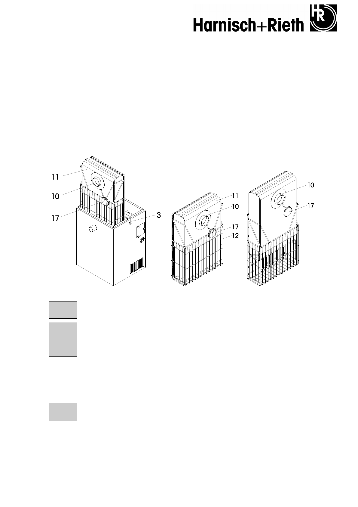
6.1 Replacing the filter bag
(See Figure 2 and 3 on Page 4 and Page 5)
1. Open the 2x quick-action closures (3) and remove cover (2).
2. Push away the plastic connector (10) from the nozzle (15) with both hands,
3. Close the filter bag (11) with attached plastic cover (17).
4. Take the filter bag (11) in the wire basket (12) to the disposal point.
Fig. 16 Removing the filter bag
Caution The disposable filter bag should never be emptied and reused as, apart from health considera-
tions, this will lead to malfunctions.
Caution Compressed air should not be used to remove any dust present in the filter
chamber (20).
No foreign objects should reach the extraction channel (26) as otherwise the extraction motor can
be damaged.
5. Insert a new filter bag and check the filter system, see section 4.2.
6.2 Inserting the filter bag
(See Fig. 2 and 3, Page 5)
Note Disposable - Paper filter bag Item No. 42 015
Disposable - Fleece filter bag Item No. 42 303
1. Fold the new filter bag (11) and place it in the wire basket (12) as shown in Figure 17.
Other manuals for D-LE 255 S
1
This manual suits for next models
1
Table of contents
Other Harnisch+Rieth Dental Equipment manuals


