Harper Goossen User manual


Thank you for purchasing a Harper/Goossen Power Plate.
This manual gives assembly, operating, and service information for Harper/Goossen Power Plate only.
Please read and understand all instructional materials included with the Power Plate before assembling
and operating the equipment.
The Power Plate can present hazards to an operator who follows unsafe procedures in either the operation
or maintenance of the unit. Therefore, SAFETY WARNINGS are presented at certain locations in the text.
Harper Industries is not responsible for accidents or injuries that result from the misuse or lack of maintenance of the
Power Plate.
SYMBOL: SAFETY WARNING!
Whenever this symbol is used, please pay very close attention to the information presented, and make sure
you fully understand. If you do not, contact your dealer or Harper Industries for clarification.
Failure to understand and obey this warning may result in injury to you or others.
SPECIAL TERMS: RIGHT AND LEFT
When used to indicate sides of the equipment, refer to the equipment from the operator’s viewpoint while
the equipment is being operated. The right side of the equipment is thus the side on the operator’s right as he or she
is operating it.
Copyright © 2003 Harper Industries, Inc.
The Goossen and Harper/Goossen names are registered trademarks of Harper Industries, Inc. All other brand and product
names are trademarks or registered trademarks of their respective companies.
Harper Industries, Inc., is continually striving to improve the design and performance of its
products. We reserve the right to make changes in specifications and design without thereby incurring
any obligation relative to previously manufactured products
3

LIMITED WARRANTY
The Harper/Goossen Power Plate is warranted against defects in work-
manship and materials for a period of TWELVE MONTHS from the date of
retail purchase to the original purchaser.
Harper Industries will repair or replace, at our option, any part that our
examination shows to be defective. Warranty is limited to parts, labor and
ground freight delivery of replacement parts. The user will pay freight charges
for parts submitted under this warranty.
No product or part may be returned for warranty consideration without
prior approval from Harper Industries.
This warranty does not apply to parts subjected to misuse, abuse, alter-
ation, improper or inadequate maintenance, or normal wear. Modifying the
Power Plate may void warranty.
Harper Industries, its agents or representatives, make or imply no other
warranties.
RECORD
Date of Purchase ______ / ______ / ______
Dealer’s Name _________________________________________
Dealer’s Phone _________________________________________
Serial Number - Power Plate _______________________________
Serial Number - Hydraulic motor _____________________________
4

Power Plate S
pecifications
Attachment Conventional skid loader quick-attach
3-Point Hitch Category-1
Construction Heavy-duty ¼” plate steel
Finish Polyurethane paint with epoxy primer
Weight 280 lbs.
5.4 cu. in. For standard skid loader systems
with 14 - 18 gpm
Hydraulic Motor
7.1 cu. in. For high-flow skid loader systems
with 19 - 28 gpm
PTO
Horsepower
Horsepower (hp) delivered to the Power Plate PTO is
determined by the following formula: hp = gpm x psi / 1714
Limitations The Power Plate is not recommended for use with brush
cutters having a single blade greater than 50” in diameter.
Operate conventional PTO-powered implements:
The Power Plate is a unique attachment that can be used to operate conventional PTO-
powered implements that have a Category-1 3-Point hitch. Care should be taken, however, not to
use implements that excessively twist the structure of the Power Plate, e.g.: brush cutters with
single blades greater that 50” in diameter.
Easy attachment to standard skid loaders:
The Power Plate is attached to a standard skid loader with the “quick-attach” mechanism
where the bucket would normally be located. Compatible skid loaders include: Bobcat, New
Holland, John Deere, and Case IH, as well as several other brands.
Available horsepower:
The horsepower generated by the hydraulic motor is dependent upon the capacity of the
skid loader. Hydraulic horsepower (hp) can be determined using the following formula:
hp (horsepower) = gpm (gallons per minute) x psi (pounds per sqare inch) / 1714.
Thus, if a skid loader has 18 gpm flow and 2500 psi, the Power Plate would be capable of
generating approximately 26 hp.
5

Control Identification Safet
y
Section
SAFETY WARNING!
Altering this equipment in any manner
which adversely affects its operation,
performance, durability, or use will void
the warranty and may cause hazardous
conditions.
EQUIPMENT & CONTROLS
• READ AND UNDERSTAND THE
OWNER’S MANUAL BEFORE
OPERATION.
• Know the location and function of all
controls and how to stop this equipment
quickly in an emergency before you
operate the equipment.
THREE POINT HITCH ARMS: Used to
secure implements to the skid loader
attachment.
• Keep the equipment and attachments in
good operating condition.
CENTER LINK: Used to secure implements
to the skid loader attachment and adjust to
level position.
• Keep all guards and shields in place
during operation.
HYDRAULIC MOTOR: Powers implements
that are attached to the unit.
• Replace all worn, damaged, unusable,
missing, or lost safety shields before
operating the equipment.
HYDRAULIC HOSES: Connect to the remote
hydraulics of the skid loader in order to
transfer power to the hydraulic motor.
• Keep nuts, bolts, and screws tight to help
ensure the safe operation of equipment.
STABILIZER BAR: Secures to right three
point hitch arm and keeps implements from
swinging from side to side.
• Use genuine factory parts or parts with
equivalent safety specifications and
characteristics, including type, strength,
and material. Failure to do so may result
in product malfunction and possible injury
to the operator and/or others.
CHECK VALVE: Ensures that motor is
running in the proper direction and protects
against cavitation during flywheel spin-down.
Note: The check valve on the Power Plate
ensures that the hydraulic motor will only turn
in the direction of a conventional tractor PTO.
• Replace locknuts and locking screws if
you can tighten them without feeling
considerable resistance for several turns
before they are completely tight. Replace
them with factory authorized parts or their
equivalent.

OPERATIONAL SAFETY
• If hardware is not secure, or if some
hardware is over-tightened, equipment
failure may result, posing possible safety
hazards.
• READ AND UNDERSTAND THE
OWNER’S MANUAL COMPLETELY.
• Be familiar with all the skid loader controls
and know how to stop quickly.
SAFETY DECALS
• NEVER operate equipment in the vicinity
of bystanders or children.
• If safety or instructional decals become
illegible or are removed, replace them
immediately.
• Always wear the proper safety gear ( for
eyes, hands, head, ears, etc.) when
operating equipment.
• If you replace parts that have such decals
attached to them, make sure the decals
are replaced with current versions, and
that the decals are on the replacement
parts before equipment is operated again.
• Never wear loose fitting clothing while in
the vicinity of the PTO shaft.
• Keep all guards and shields in place.
• New decals may be obtained from the
following address:
• Operate equipment at ground level.
NEVER operate equipment in an elevated
position. This could lead to serious injury
or even death.
Harper Industries
151 E Highway 160
Harper, KS 67058
800-835-1042
• DO NOT make adjustments to the
machine while it is running. Make sure
that the engine is shut off before working
on the machine or making adjustments.
SAFETY WARNING!
If anything in this manual is unclear or
hard to understand, contact your dealer or
call Harper Industries (800-835-1042) for
clarification before proceeding.
• Never use equipment in a manner for
which it was not designed.
Your safety or the durability and
performance of your equipment may
depend on a clear understanding of the
information contained in this manual.
• When replacing fasteners, use the
Standard Torque chart to tighten securely.
(see below)
Size In.-Lb. Ft.-Lb. N-m
No. 10-24 25-35 5-7 2.8-4.0
¼ in. 60-80 18-20 7-9
5/16 in. 120-140 28-30 14-16
3/8 in. 340-360 64-74 24-27
½ in. 126-150 90-100
SAFETY WARNING!
Wear safety glasses while operating and
servicing the equipment to prevent
possible eye injury.
SAFETY WARNING!
Use hearing protection while operating
machine to prevent possible hearing loss.

NOTE: When tightening two or more
screws on the same part, DO NOT tighten
screws completely right away, or one at a
time. To avoid distortion, first tighten all
screws in sequence to one-third of torque
value, then tighten to two-thirds of torque
value, then tighten to full value.
HOOK-UP TO SKID LOADER
1. Attach the Power Plate to the same
mounting mechanism that attaches the
loader bucket to the skid loader lift arms.
2. Attach the hydraulic hoses to the remote
hydraulics on the skid loader.
Note: The check valve allows the hydraulic
hoses to be connected to either port on most
skid loaders. However, some skid loader
hydraulic systems (e.g. Bobcat) allow one
circuit to be locked for continuous flow, thus
requiring the pressure side to match that of
the motor inlet.
Note: You will need to purchase the correct
couplers for the hydraulic hoses so that they
match your skid loader.
SAFETY WARNING!
Be sure that the Power Plate is properly
secured and fastened to the skid loader
before each period of operation.
HOOK-UP TO IMPLEMENT
1. Hook up the implement to the 3-point
hitch of the Power Plate.
2. Adjust the center link so the implement
stands at the desired level. (This can also
be accomplished by tilting the bucket
cylinder of the skid loader.)
3. Attach the PTO shaft of the implement to
the hydraulic motor on the Power Plate.
4. Be sure that the shaft is secured properly
and that all guards are in place.
Hook-u
p
& O
p
eration OPERATION
1. Adjust the placement and height of the
equipment that you intend to operate.
2. Make sure that Power Plate and
implement are attached securely.
3. With the skid loader engine running at an
idle, or low throttle, engage the remote
hydraulics. This will turn the PTO shaft
and the implement will begin to run.
4. Adjust the throttle so that the implement is
running at the desired speed.
Note: The speed (rpm) of the hydraulic
motor is dependant upon the hydraulic flow
(gpm) and pressure (psi) generated by the
skid loader. Therefore, the operator must
ensure that the implement is running at the
correct speed at all times.
SAFETY WARNING!
Never operate equipment in an elevated
position. This could cause serious injury
or even death.
Be sure that bystanders are clear of the
area where you are operating.
Never operate equipment in the vicinity of
children or pets.

POWER PLATE
PARTS
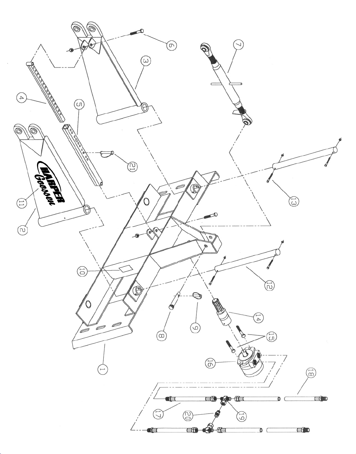

POWER PLATE - PARTS IDENTIFICATION
Item No. Part No. Qty. Description
1 915123 1 FRAME, QUICKTACH
2 915120 1 LEFT ARM
3 915121 1 RIGHT ARM
4 915122 1 STIFFENER, OUTSIDE
5 915099 1 STIFFENER, CENTER
6 110545
110219
2
2
BOLT, 7/16-14 X 2.5
NUT, 7/16-14 LOCK NYLON INSERT
7 942033 1 THIRD POINT LINK
8 110306 1 LINK PIN, 3/4" X 2-3/4", TOP
9 110305 1 PIN, LYNCH, 7/16 X 1-3/4
10 900008 1 DECAL, CAUTION
11 900017 2 DECAL, HARPER/GOOSSEN
12 910059 2 HINGE SHAFT
13 110406
110174
4
4
BOLT, 1/4-20 X 2.25
NUT, 1/4-20, LOCK (2-WAY)
14 942037 1 SPLINE ADAPTER, 1" SHAFT
15 110429
110615
2
2
BOLT, 1/2-13 X 1.5
NUT, 1/2-13, LOCK UNI-TORQUE
16 900045
900069 1 MOTOR ASSY, 5.4CI
MOTOR ASSY, 7.1CI
17 922002 2 HOSE, HYDRAULIC, SHORT
18 922003 2 HOSE, HYDRAULIC
19 120270 2 ADAPTER, 8MJ-8MJ-8FJX
20 922001 1 VALVE, CHECK 8MJ-8MJ, 5 PSI
21 110304 1 LOCK PIN, SQ, 3/8 X 2.5, WIRE
Table of contents


