Chamberlain Clopay HPH1 User manual

HPH1
High Performance Hoist
INSTALLATION MANUAL
LiftMaster
300 Windsor Drive
Oak Brook, IL 60523
LISTED
LISTED
0
12
24
36
48
60
72
84
96
108
120
132
144
156
168
180
192
204
216
CAMERA-READY LOGOTYPE OF THE UL LISTING MARK FOR CANADA AND THE U.S.
These Marks are registered by Underwriters Laboratories Inc.
ULUS LISTED
C
ULUS LISTED
C
ULUS LISTED
CULUS LISTED
C
ULUS
C
LISTED
C
US
UL
ULUS
C
LISTED
ULUS
C
LISTED
ULUS
C
LISTED
The minimum height of the registered trademark symbol shall be 3/64 of
an inch. When the overall diameter of the UL Mark is less than 3/8 of an inch,
the trademark symbol may be omitted if it is not legible to the naked eye.
Please note:
Not all of these elements should be used together with the same UL Mark.
The word “LISTED” would only be used once — either to the right of or
below the UL Mark (as shown).
The font for all letter forms is Helvetica Condensed Black, except for
the trademark symbol , which is Helvetica Condensed Medium.
No other fonts are acceptable.
RELATIVE DESIGN & PROPORTIONS OF THE UL LISTING MARK FOR CANADA AND THE U.S.
KEY TO DIMENSIONS
UL Mark
A
B
C
D
E
F
G
H
8 units
13 units
14 units
15 units
17 units
20 units
24 units
29 units
“C” and “US”
“LISTED”
P
Q
R
T
34 units
56 units
75 units
201 units
I
J
K
L
M
N
0
30 units
35 units
59 units
85 units
87 units
176 units
216 units
N
P P R
J F C F
A
F G J
M
O
Q
K
G
B
D
H
E
I
F
P
P
T
I
P
T
L
200-195S 10M/8/98
HPH1, 1.25 HP (120V/240V Single Phase & 230V Three Phase)
(460V/575V Three Phase, via stepdown transformer accessories)
NOT FOR RESIDENTIAL USE
• Please read this manual and the enclosed safety materials completely, prior to installation
and use!
• This product is to be installed and serviced by a trained door systems technician ONLY.
• These operators are compatible with myQ® Smart Facility Access™and Security+ 2.0®
accessories.
• These operators are Wi-Fi compatible.

2
TO REDUCE THE RISK OF SEVERE INJURY OR DEATH:
IMPORTANT INSTALLATION INSTRUCTIONS
1. READ AND FOLLOW ALL INSTALLATION WARNINGS AND
INSTRUCTIONS.
2. Install door operator ONLY on a properly balanced and
lubricated door. An improperly balanced door may NOT
reverse when required and could result in SEVERE INJURY
or DEATH.
3. ALL repairs to cables, spring assemblies and other hardware
MUST be made by a trained door systems technician BEFORE
installing an operator.
4. Disable ALL locks and remove ALL ropes connected to a
door BEFORE installing an operator to avoid entanglement.
5. Install an operator, a minimum of 8 feet (2.44 m) from the
floor.
6. NEVER connect a door operator to a power source until
instructed to do so.
7. NEVER wear watches, rings or loose clothing while installing
or servicing an operator. They could be caught in the door or
operator mechanisms.
8. Install a control station and/or controller:
• within sight of the door
• out of reach of children and at a minimum height of 5 feet
(1.5 m) above floors, landings, steps, or any other
adjacent walking surface
• away from ALL moving parts of the door
9. Install the control station far enough from the door to
prevent the user from coming in contact with the door while
operating the controls.
10. Install the entrapment warning placard on the wall next to
the control station in a prominent location, visible from the
door.
11. Instruct the end user on the operation of the manual
release.
12. Upon completion of installation, test the entrapment
protection device(s).
13. SAVE THESE INSTRUCTIONS.
When you see these Safety Symbols and Signal Words on the
following pages, they will alert you to the possibility of serious
injury or death if you do not comply with the warnings that
accompany them. The hazard may come from something
mechanical or from electric shock. Read the warnings carefully.
Mechanical
Electrical
IMPORTANT NOTES:
• BEFORE attempting to install, operate or maintain the
commercial door operator, you must read and fully understand
this manual and follow all safety instructions.
• DO NOT attempt repair or service of a commercial door
operator unless you are an Authorized Service Technician.
• A commercial door operator should only be installed on a
properly balanced door only. Ensure door is properly balanced
prior to installation.
SAFETY INFORMATION
ENTRAPMENT PROTECTION DEVICES:
Monitored Entrapment Protection
Monitored photoelectric sensors and/or door edge sensors are
required for any momentary contact to close modes of operation.
See page 18 for additional information. Refer to the accessories
page 42, ‘Entrapment Protection Devices’ for available options.
When you see this Signal Word on the following pages, it will
alert you to the possibility of damage to your door and/or the
door operator if you do not comply with the cautionary
statements that accompany it. Read them carefully.
WARNING: This product can expose you to chemicals
including lead, which are known to the State of California to
cause cancer or birth defects or other reproductive harm.
For more information go to www.P65Warnings.ca.gov.

3
TABLE OF CONTENTS
SAFETY INFORMATION 2
OPERATOR ...............................4-6
Carton Inventory ............................... 4
Overview ....................................4-5
Operator Specifications .......................... 6
INSTALLATION .................................7-18
Preparing the Operator for Mounting................ 7
Mounting the Operator........................... 8
Installing the Cable Tension Monitor ................ 9
Connect the Hoist Release ....................... 10
Low-Voltage Wiring of the Powerhead.............. 11
Wiring the Incoming Power to the Powerhead ....... 12
Wiring the 3-Phase Stepdown Transformer.......... 13
Mounting the Controller......................... 14
Controller Specifications ........................ 15
Wiring the Controller .........................16-17
Wiring the Monitored Entrapment Protection ........ 18
Installing the Monitored Light Curtain .............. 19
PROGRAMMING.......................... 20-33
Menus ....................................20-22
Reset Defaults ................................ 23
Operating Mode Overview ....................... 24
Configuring the Relay Adapter .................... 25
Auxiliary Relays ............................... 25
Radio, myQ®Devices, & Remotes ................. 26
Erasing Programmed Devices .................... 26
Connecting to myQ®Smart Facility ................ 27
Provisioning Wi-Fi ............................. 27
Determine and Set Operating Mode..............28-33
TROUBLESHOOTING ....................... 34-36
MAINTENANCE..............................37
Maintenance Schedule .......................... 37
Life of Operator Feature ......................... 37
How to Order Repair Parts....................... 37
CONTROLLER WIRING DIAGRAM .................38
ACCESSORY WIRING DIAGRAM . . . . . . . . . . . . . . . . . .39
OPERATOR DIMENSIONS ......................40
REPAIR PARTS & SERVICE KITS .............. 41-42
ACCESSORIES . . . . . . . . . . . . . . . . . . . . . . . . . . . . . .43
WARRANTY ...............................44
CONNECTIVITY
• myQ®Smart Facility Access Technology enables secure monitoring and control of door operators and other
myQ®Smart Facility Access devices with a smartphone, tablet or computer.
• Alerts can be received as email notifications, ensuring the status of a commercial door.
SAFETY AND SECURITY
• Security+ 2.0®– with every press of the button, a new code is sent to the commercial door operator, ensuring a door will only open
for the remote control programmed.
UL 325 requires all commercial door operators to be either constant pressure to close or be equipped with a primary external monitored
entrapment protection device.
LiftMaster®is the leading brand of professionally installed commercial door operators and access control products for businesses
worldwide. We are committed to quality products, innovative designs and comprehensive services which exceed our Customers’
expectations.

4
Cable Tension Monitors
Door
Monitored Eye/Edge
(Light Curtain)
VFD Controller
Operator
Power, Encoder,
and Data Cables
(same conduit)
Warning Placard
Cable
OVERVIEW
Hardware
Wall Brace
Conductor Power
Cable (Black)
LiftMaster Monitored
Entrapment Protection
(CPS-OPEN4)
VFD Controller
Operator
Cable Tension
Monitor (2)
Data Cable
(black)
Data Cable
(black)
NOT PICTURED:
Hoist Chain,
Threadlocker,
Sash Chain Bracket
Emergency Placard
Encoder Cable (gray)
is pre-attached to controller
*
CARTON INVENTORY
Before beginning installation, confirm all components are enclosed. Additional key stock in manual bag is provided for mounting
operator to 1-1/4” door shaft
Wall Brace

5
OVERVIEW (CONT.)
To prevent possible SERIOUS INJURY or DEATH:
•DO NOT connect electric power until instructed to do so.
• If the door lock needs to remain functional, install an interlock
switch.
•ALWAYS call an Authorized Service Technician if door binds,
sticks, or is out of balance. An unbalanced door may NOT
reverse when required.
•NEVER try to loosen, move, or adjust doors, door springs,
cable, pulleys, brackets, or their hardware. ALL of which are
under EXTREME tension and can cause SERIOUS PERSONAL
INJURY.
•Disable ALL locks and remove ALL ropes connected to door
BEFORE installing and operating door operator to avoid
entanglement.
•Fasten the operator SECURELY to structural supports of the
building.
•Concrete anchors MUST be used in installing ANY brackets.
Encoder
Junction box
Hoist chain
Step Drill Bit
(must accommodate
5/16" and 3/4" gradations)
Pliers Wire Cutters
Wire Strippers
Claw Hammer
Flat Head Screwdriver
Phillips Screwdriver
Level
3/4" Open End Wrench
1/4" and 3/4" Sockets
and Wrench with
6" Extension
Drill Tape Measure
Stepladder
Pencil
Needle Nose Pliers
5/32", 3/16", 5/16"
and 3/4" Drill Bits
Snap Ring
Pliers
TOOLS NEEDED
Wall brace

6
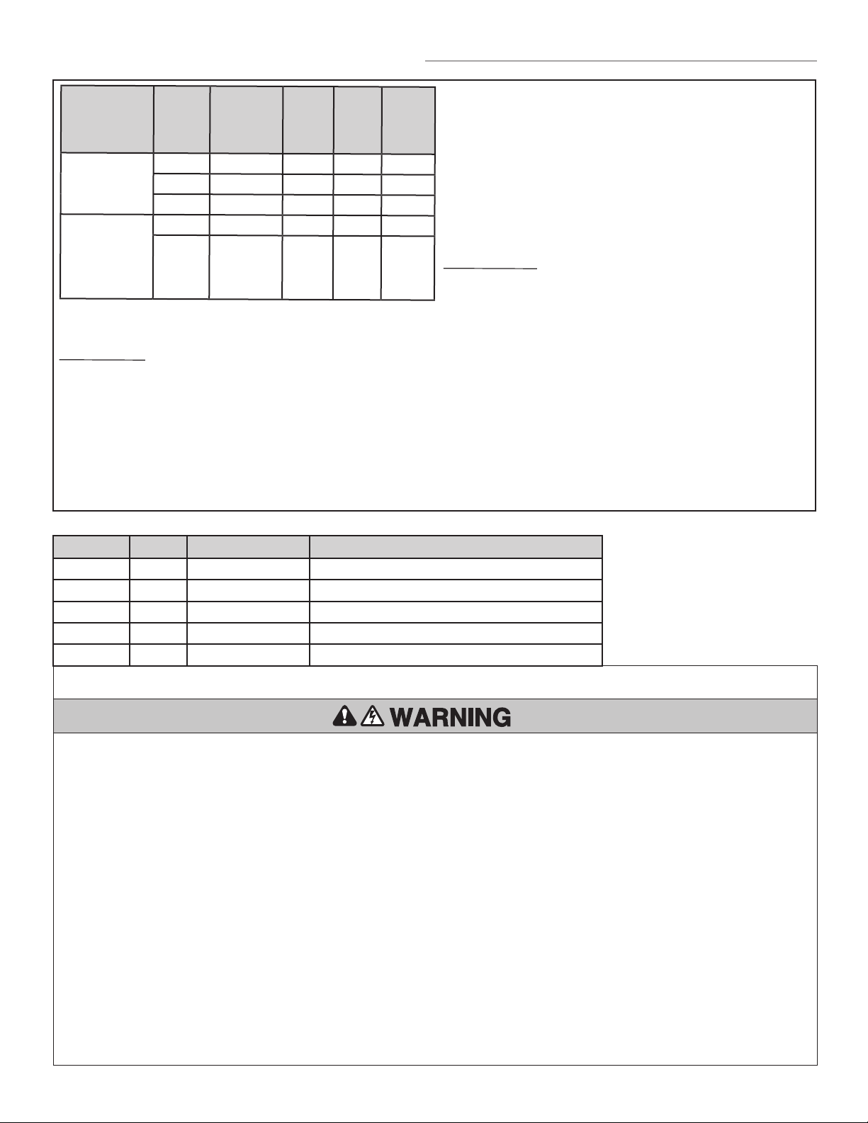
MODEL HP VOLTAGE PHASE AMPS POWER
(FT
LBS/
SEC)
HPH1
1.25 HP 120V 116A 348
1.25 HP 240V 1 9A 348
1.25 HP 230V 39A 348
HPH1 W/
STEP DOWN
TRANS-
FORMER
1.25 HP 460V 34A 348
1.25 HP 575V 34A 348
TYPE: Limited Duty: up to 100 cycles per hour
up to 600 cycles per day
ELECTRICAL
DOOR IN MOTION RELAY: 5A @ 42Vdc
AUXILIARY OUTPUT VOLTAGE: 24Vdc ; 500mA
CONTROL STATION: VFD Controller with Integrated Open/Close/
Stop Controls, LCD Display, floor level
wiring, and floor level commissioning
through intuitive user menu.
OPERATING MODES: B2, C2, D1, E2. See page 23 for more
information regarding operating modes.
BRAKE: Solenoid powered-off brake standard on all
units.
MANUAL HOIST: Manual hoist with integral manual operation
protection circuit.
CABLE TENSION MONITOR: Detects ANY slack that may
occur in the cables and responds
accordingly.
MECHANICAL
DRIVE REDUCTION:
1.25HP Operator: 20:1 High-Efficiency 2-Stage
Gearbox.
DOOR SPEED: Automatically set based on door type.
LIMIT ADJUST: Electronic limits, Floor level adjustability up
to 20ft.
TEMPERATURE RATINGS: -20°C (14°F) to +40°C (104°F)
ENVIRONMENT: For indoor use only.
MAX. DOOR WEIGHT: 92–1025 lbs
DOOR DIMENSIONS (W X H): 8'x7' – 16'x14'
OPERATOR SPECIFICATIONS
VOLTAGE SELECTION
MODEL HP VOLTAGE PHASE
HPH1 1.25 120V 1 Phase
HPH1 1.25 240V 1 Phase
HPH1 1.25 230V 3 Phase
HPH1 1.25 460V 3 Phase (via separate stepdown transformer)
HPH1 1.25 575V 3 Phase (via separate stepdown transformer)
TO REDUCE THE RISK OF SEVERE INJURY OR DEATH:
IMPORTANT SAFETY INSTRUCTIONS
1. READ AND FOLLOW ALL WARNINGS AND INSTRUCTIONS.
2. ALWAYS keep remote controls out of reach of children.
NEVER permit children to operate or play with door control
push buttons or remote controls.
3. ONLY activate a door when it can be seen clearly, it is
properly adjusted and no obstructions exist in the path the
door will travel.
4. Personnel should keep away from a door in motion and
ALWAYS keep a door in sight until completely closed. NO
ONE SHOULD CROSS THE PATH OF A MOVING DOOR.
5. NO ONE SHOULD GO UNDER A STOPPED OR PARTIALLY
OPENED DOOR.
6. If possible, use the manual release handle to disengage a
door ONLY when a door is CLOSED. Weak or broken springs
or an unbalanced door could result in an open door falling
rapidly and/or unexpectedly causing SEVERE INJURY or
DEATH.
7. NEVER use manual release handle unless the doorway is
clear of persons and obstructions.
8. After ANY adjustments are made, the entrapment protection
device(s) MUST be tested. Failure to adjust the operator
properly may cause SEVERE INJURY and DEATH.
9. Entrapment protection device(s) MUST be tested every
month. Failure to adjust the operator properly may cause
SEVERE INJURY and DEATH.
10. ALWAYS KEEP DOOR PROPERLY BALANCED. An
improperly balanced door may NOT reverse when required
and could result in SEVERE INJURY or DEATH. See the door
manufacturer’s owners manual.
11. ALL repairs to cables, spring assemblies and other
hardware, ALL of which are under EXTREME tension, MUST
be made by an Authorized Service Technician.
12. ALWAYS disconnect electric power to the door operator
BEFORE making ANY repairs or removing covers.
13. SAVE THESE INSTRUCTIONS.

7
INSTALLATION
1
2
3
1
2
3
1
2
3
VFD Cable
Fasteners
Mounting
bracket
Set screws
Encoder Cable
5-1/4" Square key
w/ #6-32 set screws
PARTS NEEDED FOR MOUNTING
PREPARING THE OPERATOR FOR MOUNTING
MOUNTING TO A 1-INCH DOOR SHAFT
This operator will arrive with a shaft adapter pre-installed onto the
gear reducer output shaft. The adapter includes a captive key, and is
needed to reduce the diameter of the gear reducer output from
1 1/4” to 1”. If installing on a 1 1/4” door shaft, remove the shaft
adapter using exterior snap ring(s) and use a 5-1/4” long key with
set screws, provided in the hardware bag.
Use a 1/16” Allen hex key for the set screws. Use the Loctite
provided to secure the set screws in place. Include images from the
Addendum.
Prior to sliding the operator onto the door shaft, align the key of the
adapter with the keyway on the door shaft by rotating the gear
reducer output shaft.
1. Pull the Hoist Engage rope straight down, until the yoke rotates
clockwise and seats in the Hoist Engage orientation.
If the yoke does not rotate, do not apply excessive force to the
rope. Instead slightly rotate the hoist wheel manually, then pull
on the rope.
2. Pull and hold the sash chain to release the brake.
3. Rotate the hoist wheel to rotate the output shaft.
Hoist
engage
rope
Hoist
yoke
Sash chain
Hoist
wheel
Brake release
lever
Power cable
(black)
Encoder cable
(gray, attached to operator)
*Hardware for affixing to wall is not provided.
Data cable
(black)
Hoist
disengage
rope
Bracket Fasteners (2)
*

8
POWERHEAD INSTALLATION
STEP 1:
Mount the operator as close as possible to the
door’s bearing plate, while allowing the junction
box cover to open a minimum of 90 degrees.
The door shaft should pass completely through the
reducer with a minimum shaft extension of 2".
STEP 3:
Align the operator vertically on the door shaft and
slide the wall brace until the base is flush with the
wall.
Tighten the bolts attaching the bracket to the
operator once the positioning of the opener is
correct.
STEP 2:
Attach the wall brace to the operator using the
supplied fasteners, but do not fully tighten them.
The wall brace can be attached to either side of the
operator, depending on whether a left or right
handed installation is desired.
STEP 4:
Use the holes in the wall brace to mark drill holes
on the wall.
Temporarily move the operator and the wall brace
aside in order to drill the mounting holes Use
proper 1/2" diameter bolts for the mounting
surface. Once the opener is seated properly,
tighten all wall and wall brace fasteners.
Mounting
holes
STEP 5:
During operator installation, write the drum number and record here:

9
1413121110987654
Drum
Cable
Cable
Tension
Monitor
Cable Tension
Monitor Roller
1/4"-3/8"
(6.4-95 mm)
INSTALLATION
INSTALLING THE CABLE TENSION MONITOR
BOTH CABLE TENSION MONITORS MUST BE CONNECTED AND
PROPERLY INSTALLED BEFORE THE DOOR OPERATOR WILL
MOVE IN THE DOWN DIRECTION.
THE CABLE TENSION MONITORS DETECT ANY SLACK THAT
MAY OCCUR IN THE CABLES AND WILL RESPOND
ACCORDINGLY.
NOTE: PLEASE USE ONLY THE LIFTMASTER CABLE TENSION
MONITORS PROVIDED WITH THE OPERATOR AS THEY HAVE
BEEN TESTED AND APPROVED FOR THIS SYSTEM.
1. Make sure the door cable is approximately 1"-2" (25-50 mm)
from the mounting surface. Door adjustments or shimming
may be required to achieve proper depth for the door cable.
The bracket must be flush with the mounting surface.
2. Position the cable tension monitor as close to the drum as
possible. The optimal distance of the cable from the wall
surface is no more than 2.5" (6.35 cm), and be sure the roller
extends 1/8"-1/4" past the cable. Make sure the cable tension
monitor and roller is free from any obstructions in all positions
of operation..
NOTE: There must be no obstructions in the installation area
that prevent the cable tension monitor from closing completely
when slack is detected.
NOTE: Cable tension monitors must either be anchored to
concrete, or a wood stud with appropriate fasteners. If neither
are available, toggle bolt style drywall anchors with at least a
50 lbs rating are acceptable.
3. Run bell wire to the door operator junction box, and down to
the control box through conduit as shown on the right.
4. Once the controller is installed, connect the bell wires parallel
to the CTM and CMN terminals on the terminals on the
controller (polarity is not important). See page 14 for installing
the wall controller. Once installed, follow these steps to
connect the wiring.
5. Connect the bell wires in parallel to the CTM and CMN
terminals on the controller. (polarity is not important)
TIP: To simplify installation, the cable tension monitors can be
wired together in the operator junction box, with only one pair
of bell wires running down to the controller.
6. Repeat Steps 1-5 for the opposite side of the door. Both cable
tension monitors must be installed for proper operation.
NOTE: Cable must have tension through entire door travel.
Make sure there is no slack in cable on opposite side of door
during normal operation. If slack occurs during door travel,
adjust cables as required.
IMPORTANT: Cable snubbers are required. Be
sure the cable snubbers are attached to each cable
near the bottom of the door on each side. These
components are provided by the door manufacturer.
Pusher springs should be used with the door system
to help get the door moving in the Close direction.
For certain types of doors, such as standard lift,
angled track may also be recommended. Please
check with the door manufacturer for details.
Cable Tension Monitors
Door
Monitored Eye/Edge
(Light Curtain)
VFD Controller
Operator
Power, Encoder,
and Data Cables
(same conduit)
Warning Placard
Cable
Drum
Cable tension
monitor
Approx. 1-2"
25-60cm
(when door is closed)
OVERVIEW
20
21 22 23 24
SBC
CMN
CTM
CMN
CABLE TENSION
MONITORS
SBC

10
INSTALLATION (CONT.)
MOUNTING CHAIN BRACKET,
PLACEMENT OF SASH CHAIN
(BRAKE RELEASE) & HOIST
CHAN
HOW TO USE MANUAL HOIST
These operators have provisions for manually operating the door
in case of emergency or power failure. Refer to the appropriate
To prevent possible SERIOUS INJURY from a moving
chain:
• DISCONNECT electric power to the operator BEFORE
manually operating your door.
• If possible, use emergency disconnect ONLY when door
is CLOSED. Weak or broken springs or unbalanced
door could result in an open door falling rapidly and/or
unexpectedly.
• NEVER use emergency disconnect unless doorway is
clear of persons and obstructions.
These operators are equipped with a manual hoist. An electrical
interlock will disable the electrical controls when the hoist is used.
To operate the hoist:
1. Install chain bracket to the wall, near control box.
2. Pull down on the hoise engagement rope, engaging the hoist/
interlock.
3. Pull the brake release chain (sash chain) to release the brake.
The sash chain may be locked in position by slipping the end
through the keyhole of the wall mounted chain keeper bracket.
4. Operate the door in the desired direction by pulling on one
side or the other of the continuous loop chain.
NOTE: The door may drift slightly depending on door balance.
To maintain the door’s position in a desired location, release
the brake sash chain and reengaging the brake.
5. To restore standard electrical operation to the operator, pull
the hoist disengagement rope to disengage the hoist/interlock.
Sash chain and
bracket
Hoist chain
hangs freely

11
POWERHEAD WIRING
5-pin connector will
be secured to the
data cable.
Knockouts to door control
for routing wires for data, power,
encoder, and optionally the cable
tension monitors.
2-pin connector will be
secured to the power cable.
This knockout is optional for routing
wires for the cable tension monitors
into the J-box. If used, these wires
would then be routed from the J-box
to the door control.
NOTE All cables and wires are able to exit through
one conduit exit point.
Hardware
Wall Brace
Conductor Power
Cable (Black)
LiftMaster Monitored
Entrapment Protection
(CPS-OPEN4)
VFD Controller
Operator
Cable Tension
Monitor (2)
Data Cable
(black)
Data Cable
(black)
NOT PICTURED:
Hoist Chain,
Threadlocker,
Sash Chain Bracket
Emergency Placard
Encoder Cable (gray)
is pre-attached to controller
*
Data Cable (black)
Power Cable (black)
Hardware
Wall Brace
Conductor Power
Cable (Black)
LiftMaster Monitored
Entrapment Protection
(CPS-OPEN4)
VFD Controller
Operator
Cable Tension
Monitor (2)
Data Cable
(black)
Data Cable
(black)
NOT PICTURED:
Hoist Chain,
Threadlocker,
Sash Chain Bracket
Emergency Placard
Encoder Cable (gray)
is pre-attached to controller
*
Encoder Cable (gray)
LOW-VOLTAGE WIRING FOR THE POWERHEAD
1. Locate the black 4-wire data cable with a green 5 pin connector at one end.
2. Locate the black 2-wire Power Cable with a green 2 pin connector at one end.
3. Locate the grey 4-wire encoder cable attached to the operator.
4. Route the encoder cable, power cable, data cable, and cable tension monitor wire through the conduit to the wall controller.
Keep the connector end at the powerhead. Route the loose end down to the door controller.
Use the slots in the lower surface of the junction box along with cable ties as strain reliefs for the cables.
NOTE: All wires will fit in a single 1/2" conduit , but two 1/2" conduits can be used if desired.
5. Plug the 5-pin and 2-pin connectors into the inverter board
LOW VOLTAGE
5
1
2
4
3

12
INCOMING POWER WIRING
SW1
230V
115V
INPUT VOLTAGE SELECTOR
230V
Incoming power can be wired
from either the right or
left side.
Connect the Line and Neutral wires
to this connector.
Connect the Earth Ground wire to
the green wire with a wire nut.
All compound knockouts
can accept 1/2" or 3/4"
conduit threaded fittings.
When securing cables to the control
board, make certain the connectors are
attached in the orientation indicated.
12
4
3
To reduce the risk of SEVERE INJURY or DEATH:
• Disconnect electric power BEFORE peforming ANY wiring or
adjustments.
• All wiring MUST be performed by a trained door systems
technician.
DO NOT ATTACH POWER AND DATA
connectors with reverse orientation, as
shown here.
To prevent SERIOUS INJURY or DEATH:
• Disconnect electric power BEFORE performing any wiring or
adjustments.
• All wiring MUST be performed by a trained door systems
technician.
• Do not invert power and data cables simultaneously.
• Do not attach power and data connections with reverse
origentation.
When installing conduit and routing
wires in J-Box, be aware of and avoid
wire hut located in lower left corner.

13
INSTALLATION (CONT.)
4-PRO TIPS FOR 3-PHASE POWER
The operator accepts 120 VAC/240 VAC single phase power only.
To use 3-phase power, follow these instrucitons:
1. Make sure the transformer is fully installed and secured with
proper hardware. For 230 V 3-phase, tap any 2-phase leges
and using 12-14 AWG wire, connect them to the “L” and “N”
terminals on the filter board. Include an earth ground
connection.
2. For 480 VAC and 600 VAC 3-phase, a stepdown transformer is
required. There are separate transformers for the two voltages.
Contact Clopay to order a transformer.
3. Mount the transformer vertically. Use the side knockouts and
route all wiring in conduit. Ensure the transformer is properly
connected to earth ground. Use an appropriately-sized circuit
breaker and power the transformer from a separate branch
circuit. Consult a licensed electrician for questions about
graounding and load balancing If drawing power from a corner
grounded delta transformer. Do not use the grounded phase.
4. Tap any two phase legs of 480 VAC or 600 VAC and connect to
the appropriate transformer primary wires using wire nuts. The
output wil be 240 VAC single-phase. Before connecting power
to the operator, measure the output and ensure the voltage is
240 VAC +/- 10 percent. Remove power from the transformer
and using 12-14 AWG wire, connect the “L” and “N” terminals
on the filter board of the operator. Include an earth ground
connection.
To prevent damage to the controller:
• Ensure that incoming power is properly bonded to earth
ground
• Verify voltage before making connections at the controller.
• Consult a licensed electrician for questions about
grounding and load balancing.

14
INSTALLATION
MOUNTING THE CONTROLLER
1. Using appropriate mounting hardware (not supplied), mount
the controller to the wall near the operator at least 5 feet
(1.5m) above floors, landings, steps, or any other adjacent
walking surface. This minimum distance should be measured
from the ground to the bottom of the Stop button.
The installation surface must be smooth and flat.
TIP: The top left or bottom right screw can be installed
loosely prior to mounting and used to retain unit during
installation.
2. Fasten the entrapment warning placard next to the controller.
If necessary, additional conduit knockouts are available.
IMPORTANT: TO PREVENT FRACTURING, ENSURE THE COVER IS
SCREWED COMPLETELY CLOSED BEFORE PUNCHING OUT ANY
KNOCKOUTS.
To prevent possible SERIOUS INJURY or DEATH from
electrocution:
• Be sure power is NOT connected BEFORE installing the door
control station.
To prevent possible SERIOUS INJURY or DEATH from a closing
door:
• Install the door control within sight of the door, out of reach of
small children, at a minimum height of 5 feet (1.5 m) above
landings, steps, or any other adjacent walking surface, and away
from ALL moving parts of the door.
• Install the control station far enough from the door to prevent
the user from coming in contact with the door while operating
the controls.
• Install the entrapment warning placard on the wall next to the
control station in a prominent location visible from the door.
• NEVER permit children to operate or play with door control
push buttons or remote controls.
• Activate a door ONLY when it can be seen clearly, is properly
adjusted and no obstructions exists in the path the door will
travel.
• ALWAYS keep the door in sight until completely closed.
NEVER permit anyone to cross path of a closing door.
Fig. 1
Fig. 2

15
CONTROLLER SPECIFICATIONS
Auxiliary expansion board
Display board
Stop/enter button
Aux board connector
Antenna port
(factory installed)
1/2" conduit
1/2" conduit
(must be knocked out to use)
1/2" conduit
Up button
Down button
ATTENTION: If the ribbon
connector cable for the
front panel has been
disconnected, ensure that
it is reconnected before
operation. The motor will
not run without this cable
connected.
1/2" conduit
(must be knocked out to use)
0.4" antenna knockout
(10.25 mm)
0.63" antenna knockout
(16 mm)

16
CONTROLLER WIRING
1. WIRING THE ENCODER
Locate the encoder cable coming from the power head
junction box. Route the cable to encoder terminals located
on the right side of the control board. Leave several inches
of slack in the cable and trim to length, if necessary. If the
cable does not need to be trimmed, skip to step 3.
Keep the cut end of the cable for reference and prepare the
cable end as follows:
2. ENCODER CABLE TERMINATION
a. Remove 2 1/2” of outer jacket insulation.
2-1/2"
b. Separate and pull back the outer shield braid. Locate and
retain the shield drain wire.
Shield Drain Wire
Braid
Braid
Foil
c. Remove the shield braid and foil wrap. Separate the wires.
Blue
Orange
White/Blue
White/Orange
d. Wrap electrical tape over the jacket insulation cut. Do not leave
bare shield exposed except for the shield wire. Strip 1/4” of
insulation from each wire.
Electrical Tape
1/4"
3. CONNECT THE ENCODER
Wire the cable to the controller as shown.
1. WIRING THE DATA CABLE
Locate the data cable coming from the power head junction
box. Route the cable to encoder terminals located on the
right side of the control board. Leave several inches of slack
in the cable and trim to length, if necessary. If the cable does
not need to be trimmed, skip to step 3.
Keep the cut end of the cable for reference and prepare the
cable end as follows:
2. DATA CABLE TERMINATION
a. Remove 2 1/2” of outer jacket insulation.
2-1/2"
b. Separate and pull back the outer shield braid. Locate and
remove the shield drain wire.
Shield Drain Wire
Foil
c. Remove the shield braid and foil wrap. Separate the wires.
Blue
Gray
White/Blue White/Gray
d. Wrap electrical tape over the jacket insulation cut. Strip 1/4” of
insulation from each wire.
Electrical Tape
1/4"
3. CONNECT THE DATA CABLE
Wire the cable to the controller as shown.
1 2 3 4 5 6 17 18 19 20 21 22 23 24 25 26 27 28 29 30 31 32 33 34 35
AUX24
CMN
24VIN
CMN
INTR
LOCK
S+
S-
CMN
INVA
INVB
CMN
12V
CMN
ENCA
ENCB
CMN
STOP
CLOSE
OPEN
SBC
CMN
CTM
MONITORED
CMN
EYE
EDGE1
CMN
EYE
EDGE2
CMN
EYE
EDGE3
CLASS 2 SUPPLY +24V
ACCESSORY POWER 24VDC, 500MA
POWER CABLE TO POWERHEAD
PROGRAMMABLE
CMN
INP1
CMN
INP2
CMN
INP3
CLASS 2 SUPPLY +24V
50-HERK2
Black
Open - Output 1 (Green)
Close - Output 2 (Blue)
CABLE TENSION
MONITORS*
OPEN
SBC
CLOSE
STOP
DRY CONTACT
RELAY ADAPTER BOARD
CONTROL BOARD RED/GREEN LIGHT
RGL24LY
Red
Black
Gray
Blue
White/
Gray
White/
Blue
DATA CABLE TO POWERHEAD
Orange
Blue
Drain
White/
Orange
White/
Blue
CPS-U, CPS-UN4,
CPS-OPEN4, OES-RD16
LC36M
X X
Tx Rx
LC36M
Blue
Brown
Black
To EYE/EDGE
To CMN
White
White
Black
Ancillary (non-monitored) devices
and dry contact inputs NO/NC.
(See page 20 for programming.)
See value “XX”
NC with 8K2
NO with 8K2
NC with 1K2
NO with 1K2
NO
NC
Select appropriate
value via menu.
RELAY ADAPTER BOARD
N.O.
Com
N.C.N.O.
Com
N.C.
RED
COM
GREEN
CMN
AUX24
*NOTE: Two cable tension monitors are required for operation.
NOTE: INTR LOCK jumper MUST
be removed if switch is added.
Blue
Brown
ENCODER CABLE TO POWERHEAD

17
CONTROLLER WIRING
1. WIRING THE POWER CABLE
Locate the power cable coming from the power head junction box. Route the cable
to encoder terminals located on the right side of the control board. Leave several
inches of slack in the cable and trim to length, if necessary. If the cable does not
need to be trimmed, skip to step 3.
Keep the cut end of the cable for reference and prepare the cable end as follows:
2. POWER CABLE TERMINATION
a. Remove 2 1/2” of outer jacket insulation.
2-1/2"
Foil
b. Remove the foil wrap and separate the wires.
Black
Red
c. Wrap electrical tape over the jacket insulation cut. Strip 1/4” of insulation from
each wire.
Electrical Tape
1/4"
3. CONNECT THE POWER CABLE
Wire the cable to the controller as shown.
1 2
3 4
5 6 17 18 19 20 21 22 23 24 25 26 27 28 29 30 31 32 33 34 35
AUX24
CMN
24VIN
CMN
INTR
LOCK
S+
S-
CMN
INVA
INVB
CMN
12V
CMN
ENCA
ENCB
CMN
STOP
CLOSE
OPEN
SBC
CMN
CTM
MONITORED
CMN
EYE
EDGE1
CMN
EYE
EDGE2
CMN
EYE
EDGE3
CLASS 2 SUPPLY +24V
ACCESSORY POWER 24VDC, 500MA
POWER CABLE TO POWERHEAD
PROGRAMMABLE
CMN
INP1
CMN
INP2
CMN
INP3
CLASS 2 SUPPLY +24V
50-HERK2
Black
Open - Output 1 (Green)
Close - Output 2 (Blue)
CABLE TENSION
MONITORS*
OPEN
SBC
CLOSE
STOP
DRY CONTACT
RELAY ADAPTER BOARD
CONTROL BOARD RED/GREEN LIGHT
RGL24LY
Red
Black
Gray
Blue
White/
Gray
White/
Blue
DATA CABLE TO POWERHEAD
Orange
Blue
Drain
White/
Orange
White/
Blue
CPS-U, CPS-UN4,
CPS-OPEN4, OES-RD16
LC36M
X X
Tx Rx
LC36M
Blue
Brown
Black
To EYE/EDGE
To CMN
White
White
Black
Ancillary (non-monitored) devices
and dry contact inputs NO/NC.
(See page 20 for programming.)
See value “XX”
NC with 8K2
NO with 8K2
NC with 1K2
NO with 1K2
NO
NC
Select appropriate
value via menu.
RELAY ADAPTER BOARD
N.O.
Com
N.C.N.O.
Com
N.C.
RED
COM
GREEN
CMN
AUX24
*NOTE: Two cable tension monitors are required for operation.
NOTE: INTR LOCK jumper MUST
be removed if switch is added.
Blue
Brown
ENCODER CABLE TO POWERHEAD

18
ENTRAPMENT PROTECTION
To prevent possible SERIOUS INJURY or DEATH from a closing
door:
• Be sure power is NOT connected to the door operator BEFORE
installing the Monitored Entrapment Protection Device(s).
• The door MUST be in the fully opened or closed position
BEFORE installing the Monitored Entrapment Protection
Device(s).
To prevent SERIOUS INJURY, DEATH, ENTRAPMENT, or
PROPERTY DAMAGE:
• Correctly connect and align the photoelectric sensor.
• Install the primary monitored photoelectric sensor beam NO
HIGHER than 6" (15 cm) above the floor and within 6" of the
plane of the door.
• This is a required LMEP Device for B2, TS, FSTS, and T
operating modes and MUST NOT be disabled. For C2 and D1
wiring the installation of an entrapment protection device is
recommended.
• Monitored Entrapment Protection Devices are for use with
LiftMaster commercial door operators ONLY. Use with ANY
other product voids the warranty.
• If an edge sensor is being used on a vertical moving door,
place edge sensors on the bottom edge of the door.
• If the door construction uses a large seal plate on the bottom
edge of the door and will trigger the photoelectric sensors
when closing, use an edge sensor on the bottom edge of the
door for monitored entrapment protection.
MONITORED ENTRAPMENT PROTECTION
Protection Area
Monitored Photoelectric
Sensor 6" (15 cm) max.
above floor and from
the door.
Monitored Detect-edge
mounted to the bottom
of door.
Monitored Photoelectric
Sensor 6" (15 cm) max.
above floor and from
the door.
IMPORTANT INFORMATION ABOUT THE MONITORED
ENTRAPMENT PROTECTION DEVICES
A monitored entrapment protection device is required for most
operating modes (page 23). If a monitored entrapment protection
device is not installed, constant pressure to close will be required
from the control station.
Refer to the Accessories section (page 42) for a complete list of
monitored entrapment protection devices.
Three EYE/EDGE terminals are provided. Each terminal can accept
ONE device. For easy identification during installation, the correct
terminals are yellow.
TYPICAL ENTRAPMENT PROTECTION DEVICE(S) OVERVIEW
Wire photo eyes into
EYE/EDGE (black)
and CMN (white
wire).
These connections
are polarity
sensitive.
CMN
EYE/EDGE1
CMN
CTM
OPEN
SBC
CLOSE
CMN
EYE/EDGE2
CMN
EYE/EDGE3
CMN
INP1
MONITORED

19
INSTALLING THE MONITORED LIGHT CURTAIN
To prevent possible product damage and incorrect operation:
• NEVER scratch or paint the optical sensors.
• DO NOT drill ANY additional holes into the Monitored Light Curtain.
• Correctly connect and align the Monitored Light Curtain transmitter
and receiver.
• DO NOT bend or twist the Monitored Light Curtain.
• Oil may damage the Monitored Light Curtain cable so contamination
MUST be avoided at ALL times.
• DO NOT mount the Monitored Light Curtain where sunlight or other
external infrared light sources will shine directly into the optical sensors
of the Monitored Light Curtain receiver. If necessary, switch the
mounting side of the Monitored Light Curtain transmitter and receiver.
INSTALL ONE SET OF MONITORED LIGHT CURTAINS AS STANDALONE PRIMARY ENTRAPMENT PROTECTION
The mounting brackets must be securely fastened to a solid surface such as a wall framing. If installing the mounting brackets in masonry construction,
add a piece of wood at each location to avoid drilling extra holes in the masonry. NOTE: If the Monitored Light Curtain is installed with coil cord, the coil
cord needs to be secured so it will not interrupt the light beams.
1. Fasten the mounting brackets loosely to both Monitored Light Curtain with the screws provided.
2. Measure a maximum of 6 inches above the floor. Mark this location. The lowest optical sensor of the Monitored Light Curtain must be installed at or
below this point. In this application, in order to assure that the lowest optical sensor is mounted no higher than 6" above the ground, the light curtain
wires must be oriented at the top of the light curtain in this application.
3. Hold the Monitored Light Curtain up to the desired mounting location with the cable end pointing upward. Secure the bottom mounting bracket to the
mounting surface.
4. Make sure the Monitored Light Curtain is level and secure the upper mounting bracket to the mounting surface.
5. Tighten the screws to secure the Monitored Light Curtain to the mounting bracket.
6. Secure the other Monitored Light Curtain to the opposite side of the door following steps 2–5, making sure they are aligned.
7. Run wires to the operator.
8. Twist like colored wires together, brown to brown and blue to blue.
AMBER LED GREEN LED STATUS SOLUTION
OFF OFF No power Check wiring.
ON Blinks • Monitored Light Curtain receiver and transmitter are not aligned • Adjust the Monitored Light Curtains to correct alignment
• Obstructed light beam • Remove the obstruction
• Defective Monitored Light Curtain Receiver • Replace Monitored Light Curtain receiver and transmitter (Model
LC36M)
NOTE: : For more detailed information, please refer to Monitored Light Curtain manual 114-5541.
TEST ALL ENTRAPMENT PROTECTION DEVICES
It is the responsibility of the specifier, purchaser, installer, and property owner to ensure that, on completion, the installation of the entrapment protection devices
comply with all relevant federal, state, and local codes and regulations.
TEST THE MONITORED LIGHT CURTAIN
1. With the door in the full open position, press the close button.
2. While the door is closing, obstruct any of the light beams on the Monitored Light Curtain (the green LED on the Monitored Light Curtain Receiver will blink
when the light beam is obstructed). The door should stop and reverse.
TEST THE PHOTOELECTRIC SENSORS (IF PRESENT IN THE APPLICATION)
1. With the door in the full open position place a solid object in the path of the photoelectric sensors and press the close button. The operator should not move.
2. Remove the solid object and press the close button. The door should close.
3. While the door is closing, obstruct the photo beam by moving a solid object in the path of the photoelectric sensors, the door should stop and reverse.
TEST THE EDGE SENSORS (IF PRESENT IN THE APPLICATION)
1. With the door in the full open position, place a solid object, on the ground in the doorway. Press the close button. The operator should stop and reverse off of
the solid object.
ALIGN THE MONITORED LIGHT CURTAINS
The Monitored Light Curtain transmitter and receiver must be aligned. When properly wired and aligned the amber and green LEDs will be ON.
The amber LED is located on the Monitored Light Curtain Transmitter and the green LED is lo cated on the Monitored Light Curtain Receiver. If
the amber and green LEDs are not on, refer to the table below.
1. Open and close the door for one complete cycle to let the operator register the Monitored Light Curtain.
POWER WIRING
Do not connect wiring in the same conduit with AC power.
1. Disconnect power to the operaator.
2. Remove Connect the wires from the moitored light curtain to the operator as illustrated.
3. Reconnect power to the operator.
Monitored entrapment protection devices that are wired correctly will be auto-learned into the system.
WALL CONTROLLER MENU ACCESS
1. Enter the menu by pressing the STOP and DOWN buttons at the same time for 3+ seconds.
2. Exit the menu by pressing the STOP and UP buttons at the same time for for 3+ seconds.
To enter the dealer menu features, type the password 224. Access into the system is good for 10 minutes while commissioning the operator.

20
PROGRAMMING
INITIAL COMMISSIONING PROGRAM FLOW
IMPORTANT: All entrapment protection devices will be disconnected during the
manual commissioning steps.
The System Settings menus are password-protected.
STEP 1: To Enter PROGRAMMING
1. Press the “STOP/ENTER” and “DOWN” buttons on the inside of the controller at
the same time for 3+ seconds to enter the operator menu. If the controller is
closed, press the “Stop” then “Close” then “Open”until the unit goes into program
mode.
2. Scroll down to “SYSTEMS SETTINGS” with the “UP” and “DOWN” buttons and
press “ENTER.” You will be prompted to enter the passowrd for the operator.
3. Enter 224 as the password.
STEP 2: Select Door Settings
To select Door Hanging and Cable Drum settings, navigate to the SYSTEM SETTINGS DOOR SETTINGS submenu.
Door Hanging
Standard Lift
Door Hanging
High Lift
Door Hanging
Full Vertical
Door Settings
Select The Drum Type
Correct Drum types are needed for the corect door profile to run the system.
Standard lift drum choices are: D400-144, D525-216
Full vertical lift drum choices are: d850-132, D1100-216
High lift choices are: 48° HL, D400-54, D525-54, 60 ° HL: D5575-120, 144 ° HL: D6375-165
IMPORTANT: Once you choose your drum, allow inverter parameter to update. Once the inverter is updated, you can re-enter the menu
to set limits and learn force.
STEP 3: Set Limits
MPORTANT: When setting limit positions, it is important that the door runs in the direction of the intended
limit. Example: When setting the close limit, only use the CLOSE button. When setting the open limit, only
use the OPEN button. Using the opposite direction button will cause the limit positions to drift over time.
To set limits, navigate to the SYSTEM SETTING DOOR POSITIONS submenu.
Door Position
Open Limit
Door Position
Close Limit
Door Position
Open Mid-Stop
Door Position
Close Mid-Stop
Door Position
STEP 3: Auto Force learn
This feature is included to automatically learn forces of a door traveling in the open and close directions. If the system determines
forces required to move the door are higher compared to the learned force, it will change operation by reversing or stopping.
IMPORTANT: All entrapment protection devices will be connected and observed during the auto-force learn process.
Auto-force learn will start counting down from 6 seconds after the limits have been learned and menu is exited.
Auto-force learn will retry once if an entrapment protection device is triggered during the learn cycle.
To decrease the force required to stop/reverse the door, go to the “Force Sensing – CLOSE trigger” or “Force Sensing – OPEN trigger”
submenu. Hit enter. The default setting is level 10 (maximum force required to stop/reverse door) and can be lowered to level 1
(minimum force required to stop/reverse door.) The force sensing feature can be turned off if the application does not require it. Force
sensing can be turned off for the Open direction only, Close direction only, or both. Level 0 turns “Off” the feature.
Note: Changing the force setting from Off to On requires auto-force relearn.
To prevent possible SERIOUS INJURY or
DEATH:
• Disconnect electric power BEFORE
performing ANY adjustments or
maintenance.
• ALL maintenance MUST be performed by a
trained door systems technician.
• Please wait several seconds for capacitors to
discharge and for display to go out.
INSTALLER
PASSCODE
224
Table of contents
Other Chamberlain Industrial Equipment manuals

Chamberlain
Chamberlain LiftMaster PROFESSIONAL K79-13493-2 User manual

Chamberlain
Chamberlain 041-0182-000 User manual

Chamberlain
Chamberlain K71-B1PH-1 User manual

Chamberlain
Chamberlain LiftMaster K72-12564 User manual

Chamberlain
Chamberlain Commercial Protector System CPS-U User manual

Chamberlain
Chamberlain Commercial Protector System CPS-U User manual