Harrington Signal HS-3100 Owner's manual

Harrington Signal
HS-3100/3200
Fire Alarm Control Unit
Programming Manual
Revision 1 January 2009
Document # LT-2001HAR
HARRINGTON
FIRE ALARM
SIGNAL INC.


HS-3100/3200 Programming Manual
i
Table of Contents
1.0 Operation and Programming Concepts ......................................................................... 1
1.1 Introduction ................................................................................................................... 1
1.2 General Information ...................................................................................................... 1
1.3 Addressable Devices .................................................................................................... 2
1.5 Resetting 4-Wire Detectors ........................................................................................... 5
2.0 Editing NP Databases ...................................................................................................... 6
2.1 Introduction ................................................................................................................... 6
2.2 General Comments ....................................................................................................... 6
2.3 System Window ............................................................................................................ 7
2.4 Switches Window .......................................................................................................... 11
2.5 Groups Window ............................................................................................................. 12
2.6 Panel Window ...............................................................................................................14
2.7 Outputs Dialog .............................................................................................................. 17
2.8 Options Dialog ............................................................................................................... 19
2.9 Circuits and Devices Windows ...................................................................................... 28
2.10 Internal Circuits Window ............................................................................................. 32
2.11 Relate Window ............................................................................................................ 34
2.12 Pushbuttons ................................................................................................................ 35
3.0 LCD Programming ............................................................................................................36
3.1 Introduction ................................................................................................................... 36
3.2 General Comments ....................................................................................................... 36
3.3 Menus ........................................................................................................................... 37
4.0 Appendix A: Condition Codes and Zone Numbers ....................................................... 43
4.1 Introduction ................................................................................................................... 43
4.2 List of Codes and Zone Numbers ................................................................................. 43
5.0 Appendix B: Stand-by Battery Calculation .................................................................... 48
6.0 Appendix C: Service Terminal ........................................................................................ 49
6.1 General ......................................................................................................................... 49
6.2 Control Unit ................................................................................................................... 49
7.0 Appendix D: Table of Reporting Codes ......................................................................... 56


HS-3100/3200 Programming Manual
iii
List of Figures & Tables
Figure 1: Four Wire Device Wiring (Typical) ....................................................................... 5
Figure 2: Network Plus System Window ............................................................................. 7
Figure 3: Switches Window ................................................................................................. 11
Figure 4: Groups Window ................................................................................................... 12
Figure 5: Panel Window ...................................................................................................... 14
Figure 7: Panel Outputs ...................................................................................................... 17
Figure 8: Options Dialog ..................................................................................................... 19
Figure 9: Default Key Assignments ..................................................................................... 21
Figure 10: Dialer Settings .................................................................................................... 23
Figure 11: Dialer Configuration 1 ........................................................................................ 24
Figure 12: Dialer Configuration 2 ........................................................................................ 25
Figure 13: Call Directions .................................................................................................... 26
Figure 14: Zone Data .......................................................................................................... 27
Figure 15: Dialer Maintenance and Common Reporting Codes ......................................... 27
Figure 16: Circuits Window ................................................................................................. 28
Figure 17: Devices Window ................................................................................................ 28
Figure 18: Copy Window ..................................................................................................... 31
Figure 19: Internal Circuits Window .................................................................................... 33
Figure 20: Relate Window ................................................................................................... 34
Figure 21: Program Menu ................................................................................................... 36
Figure 22: Selector Screen ................................................................................................. 37
Table 1: Automatic Contact ID/SIA Reporting Codes ......................................................... 56
Table 2: Contact ID Zone Alarm/Restore Event Codes ...................................................... 57
Table 3: SIA Format Automatic Zone Alarm/Restore Codes .............................................. 57


HS-3100/3200 Programming Manual
1
1.0 Operation and Programming Concepts
1.1 Introduction
This chapter provides an overview of the HS-3100/3200’s (hereafter called the HS-3200) features
and supported devices.
1.2 General Information
Warnings: Before Programming
1. All applicable codes and standards should be considered when programming the Control
Unit.
2. The Control Unit continues to monitor input circuits and devices and acts according to the
current program settings if an alarm is received while it is being programmed.
3. Loading a new database erases the current database before loading the new database. If
the new database is not loaded after the erasure, the panel will not operate.
4. The database internal revision number included must match the number required by the
HS2 program, otherwise a Database Mismatch trouble condition is generated. This
condition disables the panel until a correct HS2 program is loaded.
5. The database must be completely loaded for it to be considered valid. The program keeps
track if the last database load was valid/complete or not. An invalid database load disables
the panel until a valid database load is done.
Downloadable Database
The panel uses a downloaded database for input circuit programming. This database includes the
addressable devices on-line, and the Zone LEDs, Bells, Functions Relays and Control Modules
activated by addressable devices. This database is created and downloaded from an IBM
compatible computer using the Network Plus (NP) program. Refer to the Network Plus User Guide
for instructions on downloading the database.
Note: All communications are stopped during the database load. This causes a trouble to be recorded by those
units that are normally communicating with the panel.
HS-3100/3200 Programming Manual
2
1.3 Addressable Devices
Supported Devices
The HS-3030 can use analog/addressable devices. There are two general types of devices:
sensors and modules. The following devices are supported:
The M500S control module can be used to control a supervised output, such as a bell or strobe
circuit. The control module monitors the circuit wiring and troubles will be reported. The module will
require a separate 24 VDC supply for the controlled circuit. When programming the database in
NP, be sure to program the control module correctly. Choose any “Control (str)” other than “Control
(relay)” for the M500S module. The HS-3400 will not operate a control module if the supervised
Modules
M500DM Dual Input Monitor Module
M500M Monitor module, Classes A/B initiating
M501M Mini Monitor module, Class B initiating
M502M Monitor Module for2- wire smoke detectors Classes A/B
initiating
M500S Control module
M500R Relay Module
M500X Fault isolator module
IM-10 Intelligent Input Monitor Module
CZ-6 Zone Interface Module
CR-6 Control Module Relay
SC-6 Supervised Control Module
Sensors
1251 Ionization type smoke detector, low profile
1551 Ionization type smoke detector
2251 Photoelectric type smoke detector, low profile
2551 Photoelectric type smoke detector
2251T Photoelectric type smoke detector c/w heat detector,
low profile
2551TH Photoelectric type smoke detector c/w heat detector
2251TMB Acclimate Photo-Thermal Detector
5251 Fixed temperature detector, low profile
5251H Fixed high temperature detector
5551 Fixed temperature detector
5251R Rate of Rise and fixed temperature detector, low profile
5551R Rate of Rise and fixed temperature detector

HS-3100/3200 Programming Manual
3
circuit is shorted. Also there are options in NP that affect the M500S control module but not the
M500R relay module.
The M500R relay provides two Form C relays. Choose “Control (relay)” for the M500R module.
There are options in NP that affect the M500R relay module that do not affect the M500S control
module.
The M500X isolator module is used to prevent wiring faults from affecting the entire circuit. It
divides the addressable circuit into sections. The isolator has separate IN and OUT wiring. A short
on one side of the isolator is not seen on or affects the other side. Isolator modules do not use
addresses. The isolator relies on a voltage threshold to determine whether it should be isolating or
not. This voltage threshold is around 6.5V. All isolators in a system are in isolated mode on system
power up. If there is an excess of current draw, the isolator will not close. When the short is
removed, the isolator module automatically closes the circuit again. The LED on the isolator
module turns on when the module is in isolated mode, otherwise it flashes periodically. System
Sensor recommends no more than 25 devices between isolator modules since the inrush current
of the devices may mimic a short condition preventing the isolator from closing.
The sensors all use bases for mounting. Besides the standard plain bases, there are also relay
bases, isolator bases and a sounder base. The available bases are:
The sensor LED activates the relay and sounder bases. When this LED stays on for more than 10
seconds, the base activates. This requires that the HS-3030 have the LED mode set to FLASH/
ON. This is done through the LCD Menu by choosing PROGRAM/ADDRESSABLE/LED MODE/
FLASH. The HS-3030 only turns on the LEDs of up to 5 devices per addressable circuit to prevent
excess current flow. While the panel continues to respond to further alarms from the circuit, the
panel does not turn on additional LEDs. The B501BH sounder base requires a separate 24 VDC
supply for operation. If the polarity of this supply is reversed for more than 10 seconds, the
sounder base activates.
Isolator bases function the same as isolator modules. The sensor plugged into the base is
connected to the IN wiring to the base. The isolator is between the sensor and the OUT wiring.
While both sensors and modules have rotary dials that allow for addresses from 00 to 99, modules
add 100 internally to the address programmed, thus using the address range 100 to 199. Since
sensors and modules come from the factory addressed as 00, we do not allow that address to be
used for an installed device. Address 0 is used for indication of wiring faults on the addressable
circuit.
B501 Flangeless base for all sensors
B501B Flanged base for x551 sensors
B210LP Flanged base for x251 sensors, low profile
B501BH Sounder base for all sensors
B501BHT Sounder base, temporal
B524BI Isolator base for x551 sensors
B224BI Isolator base for x251 sensors, low profile
B524RB Relay base for x551 sensors
B224RB Relay base for x251 sensors, low profile

HS-3100/3200 Programming Manual
4
Device Faults
The following troubles (with condition code letter) can be reported by or for addressable devices:
•Missing (M): A device listed in the database is not reporting back when polled by the
panel. For a new installation, this is generally indicative of devices that have been mis-
addressed. This error can also occur if there are any wiring faults.
•Illegal (I): A device is reporting in on an address that the database shows as unused. For
a new installation, this is generally indicative of devices that have been mis-addressed.
For illegal sensors, since there is no programming available, if an alarm condition is
detected, the HS-3030 operates all its bell circuits. In a network system, only the local
panel activates its bells. The HS-3200 always ignores illegal modules.
•Wrong Type (U): This occurs if the device is not the type expected for the address. For
example, the database lists an address to have a ion smoke detector, but a photo smoke
detector has reported for the address. This error is also used if the panel cannot determine
the type of the device. If the device goes into alarm, the panel operates normally.
•Trouble (T): Sensors: The device is defective and needs to be replaced.
Modules: The extended circuit from the module has a wiring fault. Note: Control modules
that supervise their output circuits are not operated if the output circuit is shorted.
•Duplicate (D): This means that two devices are using the same address. The HS-3200
does a check every hour for duplicate devices. If either device goes into alarm, the panel
operates normally. Note: Due to the method used to detect duplicate devices, it is possible
for a single device to appear as duplicate devices. Generally, the device needs to be
replaced.

HS-3100/3200 Programming Manual
5
1.5 Resetting 4-Wire Detectors
General
4-wire detectors can be reset by using one of the function relays on the panel. The relay is not
programmed for any use, that is, it is unassigned. The next requirement is that a non-zero duration
be programmed for it (See “2.7 Outputs Dialog” on page 17) A duration of zero disables this
function. Once this is done, wire the power for the device as shown in Figure 1. A third party power
supply (must be UL/ULC-listed compatible power supply suitable for fire applications) can be used
instead of the Aux Power as shown. Whenever the System Reset operator key is pressed when
neither LED is flashing, causes the relay to operate for the duration programmed.
Figure 1: Four Wire Device Wiring (Typical)
To Monitor Module
Input
4 Wire Device
COM
AUX
RLY 4
RLY 3
RLY 2
RLY 1
AUX
NC
NO
COM
NC
NO
COM
NC
NO
COM
NC
NO
+
-
+
-
+
-

HS-3100/3200 Programming Manual
6
2.0 Editing NP Databases
2.1 Introduction
This chapter describes the windows used to program the system.
2.2 General Comments
Overview
The editing of a system is done through a series of input windows. Editing starts with the System
Level and progresses to the Panel Level, then to the Input Level, and finally to the Relate Level.
The Main Menu and option speed keys are not available while editing/viewing the system. While
editing is being done, the word OPEN is displayed in the Status Bar. This is to remind the user that
the system database is open and that the computer should not be turned off. If the computer is
turned off while the database is open, it may become corrupted.
If the current database has been previously verified and you select Edit, a requester is displayed
confirming your request to edit the database. If No is chosen, then the database is displayed in
View mode. Editing the database changes the database to a non-verified state and changes the
Last Edit Date.
Prior to an editing session, the database is automatically backed up. This back up copy has the
same name as the original database, but incorporates a .BAK extension. If a database becomes
corrupted, delete it and rename its .BAK backup file to have a .DBA extension. This restores the
database to the state prior to the last editing session.
Panel Description
The HS-3200 has two (Class A or B) SLCs and two (expandable to eight) NACs. The NACs can be
programmed to be used as either bells or strobe type circuits.
The HS-3434 Annunciator can be attached to the HS-3200 panel. It is considered an
extension of the panel by
Note: When upgrading from a version 17 (or earlier) system, a number of items that were programmed
at the panel are now included in the database. See the file UPGRADE.TXT for a complete
description of these changes.
Follow these instructions to obtain the required information before upgrading your firmware:
1.Connect your computer to the panel and open the Terminal window
2.Select the Printer screen in the Terminal: press 14<Tab>
3.You should note that the title bar of the Terminal window displays the text "File logging in
progress...". If this does not appear, press the button Log On.
4.In the terminal window, type the following command: 99?
5.The panel's configuration settings will be listed in the Terminal window and it will also be
saved in the file: LOG_CONT.TXT, located in your program directory
6.Close the Terminal window
7.You may now view the contents of the file using any standard word processor or text editor
You must perform the above procedure for ALL panels in your system
HS-3100/3200 Programming Manual
7
2.3 System Window
Description
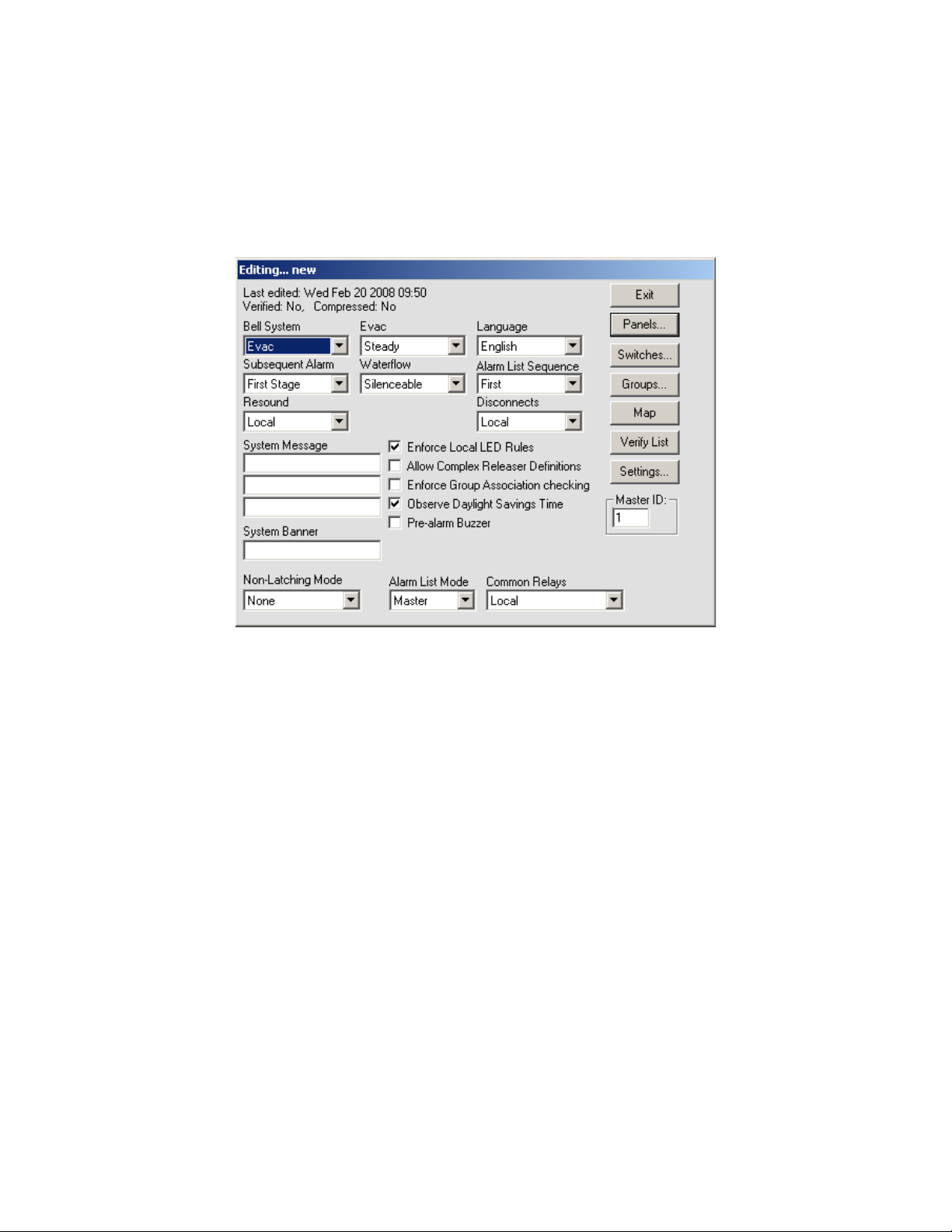
The System Window (see Figure 2) allows editing of all system level options, as well as detailing
other system wide information.
The Title Bar of the window shows whether editing or viewing of the database is being preformed
and the name of the current database.
Figure 2: Network Plus System Window
The text in the top left corner provides information about the database. The top line gives the date
and time the database was last edited. The next line states whether the current contents have
been verified or not; and whether the database has been compressed or not.
The options Bell System, Subsequent Alarm, Resound, Evac and Waterflow all affect how the
notification appliance circuits (NAC), hereafter referred to as bells, react to alarm conditions.
Bell System
Bell System is a drop down list for selecting how the bells and strobes will operate. This sets the
base operation for the entire network. If coded bells are required, the bell codes are defined for
each input individually. The following options are available:
•Alert: A First Stage alarm activates the selected bells in Alert mode. If the Signal Silence
or Second Stage Inhibit Hot Key is not pressed before the [No Acknowledge] Second
Stage Inhibit timeout, the panel will progress to Second Stage. Second stage will activate
all bells in Evacuation mode.
•Evac: A First Stage alarm will activate selected bells in Evacuation mode. Second Stage
will activate all bells in Evacuation mode. There is no timeout from First to Second Stage.
•Alert/Evac: A First Stage alarm activates the selected bells in Evacuation mode and all
other bells on the panel in Alert mode. If the Signal Silence or Second Stage Inhibit Hot
Key is not pressed before the [No Acknowledge] Second Stage Inhibit timeout, the system
will progress to Second Stage. Second Stage will activate all bells in Evacuation mode.
•Staged: The 1st alarm will activate selected bells in Alert mode. If the Signal Silence or
Second Stage Inhibit Hot Key is not pressed before the [No Acknowledge] Second Stage

HS-3100/3200 Programming Manual
8
Inhibit timeout, the selected bells are switched to Evacuation mode and the next bells, i.e.
the ones with the next higher number, are activated in Alert mode. This sequence is
repeated until all bells are in Evacuation mode. When the highest numbered bell circuit
switches to Evacuation mode, all bell and strobe circuits on the panel will be turned on in
Evacuation mode. For example, if the alarm activates Bells 1 and 4, after the NAK timeout,
Bells 1 and 4 are switched to Evacuation mode and Bells 2 and 5 are set to Alert mode. A
2nd alarm will activate all bells in Evacuation mode.
Subsequent Alarm
Subsequent Alarm controls how Alert, Evac and Alert/Evac type bell systems behave when a new
alarm is received while one is still active. 1st Stage has the panel repeat the First Stage operation.
2nd Stage has the panel go immediately to Second Stage operation.
Resound
Resound controls how the panel handles the automatic resounding of silence bells when a new
alarm is received. There are two modes:
•Local: Each panel resounds only its own silenced bells when a new alarm is received.
This would be used when panels in a network are in different buildings, such as a campus.
•Global: All panels in a network resound silenced bells when a new alarm condition is
received on any panel in the network. This is used when the panels are all in the same
building, such as a large plant.
Evac
Evac controls whether the bell system Evacuation Mode sounds Steady (continuously) or uses a
Temporal pattern as specified in ANSI S3.41 and ISO 8201 Audible Emergency Evacuation Signal.
The pattern used ½s On, ½s Off, ½s On, ½s Off, ½s On, 1½s Off repeated.
Waterflow
Waterflow controls if bells can be silenced if they are started by a waterflow type input. If Non-
Silenceable is chosen, bell circuits activated due to a waterflow input cannot be silenced until the
waterflow device has restored.
Language
Language chooses English (default), French or Hungarian characters to be used in messages.
Alarm List Sequence
Alarm List Sequence controls which end of the Alarm List is shown automatically. If First is chosen,
the first (oldest) item in the alarm list is shown. If Last is chosen, the last (newest) item in the alarm
list is shown. Regardless of order, alarms always take precedence in being shown. Another way to
think of it is that First shows where the fire started while Last shows where the fire has gotten to.
Disconnects
Disconnects controls which panels the Signal Disconnect, Relay Disconnect, Releaser Disconnect
and Common Disconnect hot keys affect.
•Local: The Disconnect hot keys affect only the panel they are on.
•Global: The Disconnect hot keys affect all the panels in the network. This means that if
any Disconnect key is pressed on a panel, all other panels in the system take on the state
of that Disconnect, either on or off.
Note: 1.Bells must be assigned consecutive bells circuits with no Releasers assigned in between Bells.
For example: circuits 1, 2, 3, 4 can be assigned as Bells but not circuits 1, 2, 4, 5 with circuit 3 a
Releaser.
2.Control modules cannot be programmed as bell or strobe if the Staged Bell system is used.

HS-3100/3200 Programming Manual
9
System Message
The System Message is a text entry box for defining a message that is 3 lines by 20 characters
that is used to identify the system. This message is printed at the top of printouts and shown on
some service terminal screens, but it is not used in any LCD except in STATUS/IDENTIFICATION.
System Banner
The System Banner is a 20 character message that is used as a banner for the Main Menu of the
LCD. The default banner is “HS-3200 by Harrington Signal”.
Enforce Local LED Rules
The Enforce Local LED Rules check box forces an LED on an input's panel be related. Normally
an LED anywhere in the system is all that is required. Note: The common LEDs of any panel are
based upon the zone LEDs that are displayed by the panel, not based upon the inputs to the
panel.
Enforce Group Association
The Enforce Group Association checking check box enables NP to check to see if a group
association has been included in the relates of inputs.
Observe Daylight Savings Time
The Observe Daylight Savings Time check box enables or disables the automatic changing of the
clock for Daylight Savings Time. If enable, the system moves 1 hour ahead the second Sunday of
March and fall back 1 hour the first Sunday of November (North American dates).
Pre-Alarm Buzzer
The Pre-Alarm Buzzer, when enabled, will cause a tone to sound when an addressable device is
in alarm during the Retard period. The tone is a triple beep repeated every second.
Master ID
Master ID defines which panel in a network acts as the Master panel. Only control panels may be
chosen as the Master panel. The Master panel retains an alarm list for the entire network and
synchronizes the date and time on all panels and annunciators at 3:30am everyday. (The alarm list
functionality is programmable for several modes of operation. See below for more detail.)
Alarm List Mode
Alarm List Mode sets the way the Alarm List messages are displayed on fire panels in the system.
Annunciators always receive messages as marked in the database. There are three modes of
displaying messages:
•Local: Each fire panel shows only Alarm List entries that are for that panel only.
•Global: Each fire panel shows Alarm List entries for itself and all other panels and
annunciators.
•Master: The master fire panel shows the Alarm List entries for all panels and annunciators
while all other fire panels show only their own Alarm List entries.
Common Relays
Common Relays controls what signals affect the common alarm, common supervisory and
common trouble relays of each panel. The are two settings:
•Local: The common relays of a panel follow the events of events on that panel only.
•follow Alarm List Mode: The common relays of a panel react to both events of the panel
and any events listed in its Alarm List.

HS-3100/3200 Programming Manual
10
Non-Latch Mode controls if the panel will auto store. The options are as follows
•More:Everything Latched
• Trouble only: Only trouble conditions will auto restore; Note some troubles require user
intervention before the panel can determine if the condition be restored
•Supv and Trbl: Supervisory and Trouble conditions will automatically restore.
Pushbuttons
The System Window has the following push buttons on the right hand side:
•Exit: Closes the System Window and, if editing, causes the database to be saved. After
an edit session, a requester asks if the database should be Verified. A database has to
verify without errors before it can be downloaded.
•Panels: Displays the Panel Window. If no panel is currently defined, the Add Panel Box is
displayed.
•Switches: Displays the Switches Window. This window determines which devices are
attached to the switches and the timers associated to each switch. See section 2.4
Switches Window.
•Groups: Displays the Groups Window. This window is used to define groups of relates.
See section 2.5 Groups Window.
•Map: Displays and/or updates the Map Window. See section 2.8 Map Window of the
Network Plus User Guide.
•Verify List: Displays the Verify List. If there is no Verify List, a requester will appear asking
whether you wish to perform a verification. See section 2.6.5 of the Network Plus User
Guide for a full description of the Verify List and its uses.
•Settings: Defines the Verify warnings to disable and/or errors to reduce to warnings for
the current database. Not all warnings/errors can be disabled/reduced. The use of this is
not recommended, but provided for special circumstances.
HS-3100/3200 Programming Manual
11
2.4 Switches Window
Overview
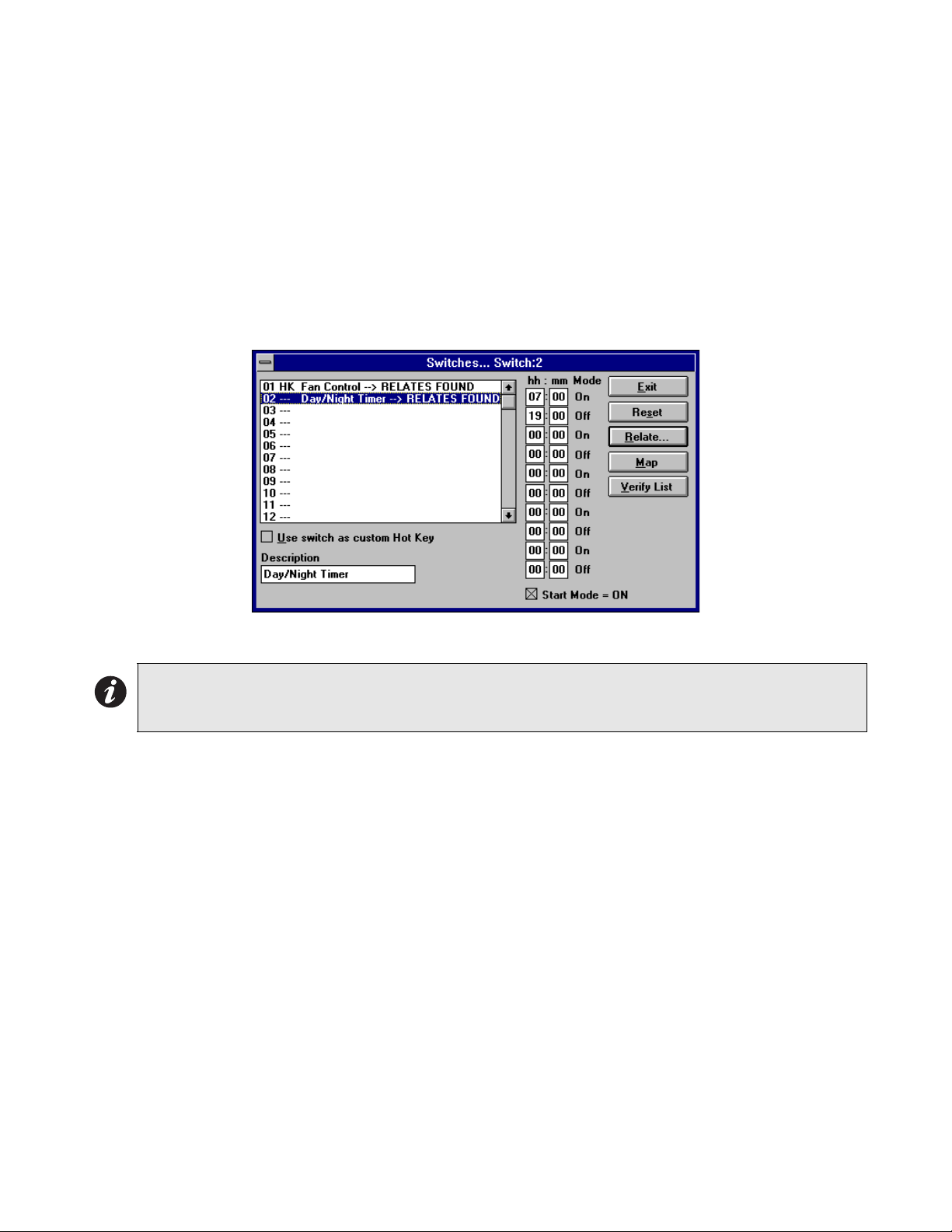
The Switches Window (see Figure 3) allows for the setting of the On/Off (Day/Night) switches.
There are 16 system wide switches available. All panels in the network keep track of their portion
of the devices related to each switch. Relays, LEDs and control modules follow the On/Off state of
the switch they are related to. Addressable sensors use Day sensitivity while the switch is on and
Night sensitivity while the switch is off. The timers can be used to have the switch change state at
set times each day. Switches can be operated manually at the panel whether they have timers or
not. If the Switch is associated to a Hot Key, the Hot Key then operates the switches, causing the
related LEDs, relays and control modules to react. Changing a switch manually at one panel
causes all panels in the network to change switch state.
Figure 3: Switches Window
The title bar of the window always lists the currently highlighted switch.
Switches Table
The Switches Table shows all 16 possible switches and highlights the current one. Select any one
to make it the current switch. List entries show the message RELATES FOUND for switches that
have related devices.
HH:MM (Timer)
The HH:MM (Timer) entries control the times that the switch changes state. An even number of
times must be entered, ie. each on must have a corresponding off. All times are entered using 24
hour notation, e.g.: one minute after midnight=0:01, noon=12:00, 3 PM=15:00, 4 AM=4:00, etc. A
time of 0:00 is considered as not used. If an action at midnight is desired set the time to 0:01, one
minute after midnight; or 23:59, a minute before midnight. NP sorts the times into ascending order
after the Switches Window is closed.
Start Mode - On
The Start Mode - On check box determines if the first time listed should turn the switch On or Off. If
it is not checked, the first time turns the switch off. If it is checked, the first time turns the switch on.
The on and off indication beside each time entry changes to reflect what each time in the sorted
list does.
Note: 1. Addressable detectors can only be related to a single switch each.
2. Relays, LEDs and control modules controlled by more than one switch stay on as long as any
switch operating them is on.

HS-3100/3200 Programming Manual
12
Use Switch as Custom Hot Key
Use switch as Custom Hot Key allows the switch to be manually controlled by the Hot Keys. A hot
key can be assigned to turn the switch on and another to turn it off. These keys are marked as HK
in the Switches Table.
Description
Description is a 20 character message that describes the Switch usage. This is useful in that the
switch now has a description of its usage that is easier to understand when assigning Switches to
Hot Keys.
Pushbuttons
There are five push buttons on the right side:
•Exit: Close the Switches Window and return to the System Window. If there are any
invalid times entered (ie greater than 23:59), NP requests corrections.
•Reset: This removes all relates and all times for the currently highlighted switch.
•Relate: Shows the Relate Window. Items marked *on* are operated/controlled by the
switch.
•Map: Displays and/or updates the Map Window. See section 2.8 Map Window of the
Network Plus User Guide.
•Verify List: Displays the Verify List. If there is no Verify List, a requester will appear asking
whether you wish to perform a verification. See section 2.6.5 of the Network Plus User
Guide for a full description of the Verify List and its uses.
2.5 Groups Window
Overview
The Groups Window (see Figure 4) is used for creating and editing the Groups of relates. The
Title Bar shows the current group.
This dialog allows you to setup "Groups" which are composed of a text description/message and
relates. Groups are a method of establishing zone representations. A zone representation may
include a message and/or a group of Relates. Inputs (ie. circuits and/or devices) may relate to a
Group or number of Groups and thus acquire all Relates that are referenced by them. Inputs can
also separately adopt the Group message. Making a change to a Group affects all inputs (circuits
and devices) related to the Group. This is a very powerful feature that can significantly speed up
the creation of medium to large size systems as well as simplify changes. Forethought should be
placed in defining appropriate Groups. Up to 250 groups may be defined.
Figure 4: Groups Window

HS-3100/3200 Programming Manual
13
The use of Groups greatly simplifies the changes made to a database as changes are needed by
the system. For example, if new door is installed that has to be unlocked during a fire alarm, the
control module that unlocks the door is simply added a Group. This single change is then
automatically picked up by any inputs that are related to the Group. Since this number could be
hundreds, the use of the Groups makes databases easier to maintain and decreases the likelihood
of mistakes when items are added.
Group List
The Group List shows all the defined groups along with their message (if any) and if there are any
relates defined for the group. The current group is highlighted. Use the <Backspace> key in order
to quickly re-position the current selection to another group.
Message Description
The Message/Description is used to enter a message for the group. This set of text-boxes allows
you to enter a message describing the Group. You are allowed space for 3 lines by 20 characters.
If desired, this message may be adopted by a circuit or device by checking the Use Grp Msg
check-box and specifying this Group ID. This is a powerful feature if you are defining a large
number of inputs that require the same message.
Pushbuttons
The following push buttons are defined:
•Exit: Close the Groups Window and return to the previous window.
•Add Group: This defines a new group ID. The new group can have any number between
1 and 250. By default, the number is the next one available. There is no need for the
groups to be sequentially numbered or to start at 1.
•Delete Group: This removes the group from the list. You are asked if you want to have
references to the group automatically removed.
•Reset Group: This removes all relates for the currently highlighted group.
•Change ID: This allows the group ID to be changed. This may need to be done if two
databases are being merged together. NP automatically changes all references to use the
new ID. A gauge is displayed to show the progress of the change.
•Relate: Shows the Relate Window. Items marked *on* are operated by inputs related to
the group. When relating inputs to groups, be sure that all relates defined by the group are
allowable for the input.
•Copy Relates: Copies the relates and/or message from an input point to the current
group. The values of the panel, circuit and device are required. Most conventional circuits
use a device number of 0 (zero). Press Copy to copy the information.
•Map: Displays and/or updates the Map Window. See section 2.8 Map Window of the
Network Plus User Guide.
•Verify List: Displays the Verify List. If there is no Verify List, a requester will appear asking
whether you wish to perform a verification. See section 2.6.5 of the Network Plus User
Guide for a full description of the Verify List and its uses.
Note: Though any relationship can be selected for inclusion into a group, an input that references the group must
be able to accommodate the group’s relates. It may be advantageous to separate groups in these cases.
HS-3100/3200 Programming Manual
14
2.6 Panel Window
Overview
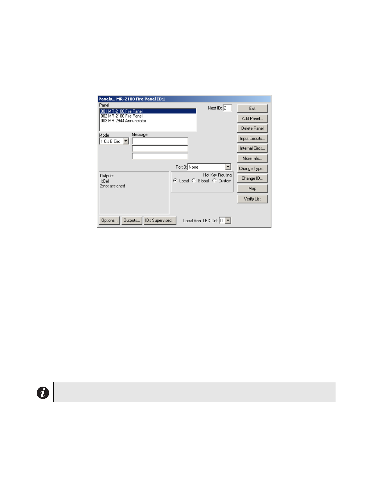
The Panel Window (see Figure 5) allows editing of all panel level options. It defines the hardware
mounted in the panel and the functionality of the programmable outputs. The programming
controls provided change to reflect the capabilities of the currently selected panel. The Title Bar
describes the currently highlighted panel or annunciator.
Figure 5: Panel Window
•Exit: Close the Panel Window and return to the System Window.
•Add Panel: Add another panel to the system. A dialog box will be displayed. The default
options are to use the next available panel ID and to select an HS-3030 panel . You will
also be asked if you want NP to automatically set the Next ID. If allowed, this panel will
have the next higher numbered panel as its Next ID and the panel with the next lower
number will be set to have this panel as its Next ID. If the new panel is the highest
numbered panel, it will use the lowest numbered panel as its Next ID.
•Delete: Remove the current panel from the system. All programming for that panel will be
lost. Any of the panel's outputs that are referenced will become invalid and will be
removed by the next verify.
•Input Circuits: Display the Circuits Window. See section 2.6
•Internal Circuits: Display the Internal Circuit Window. See section 2.7.
•More Info: This displays a dialog box listing basic information about the panel including
the date the database was last downloaded into a panel, the number of times downloaded,
etc.
•Change Type: Displays a dialog box to change the type of the current panel. This makes
it easier to correct mistakes when creating a database and to update the database if a
panel type is changed in the field. Only certain type changes are allowed.
•Change ID: Displays a dialog box for changing the ID of the current panel. NP will
automatically change all references to use the new ID. This process could take a long time
for a large database. A gauge will be displayed to show the progress of the change.
Note: This can have far reaching effects on a system. Any information that is no longer valid with the
new panel type will be lost
This manual suits for next models
1
Table of contents
Other Harrington Signal Control Unit manuals


Popular Control Unit manuals by other brands

Logic Controls
Logic Controls LM3000 Specifications

hidealite
hidealite Moon Slim quick start guide

Biamp
Biamp IMPERA ECHO installation manual

Allen-Bradley
Allen-Bradley POINT I/O 1734-4IOL installation instructions

Crystal Vision
Crystal Vision Indigo AVDELAY 3G user manual

monolith
monolith ZEUS003 INSTRUCTION FOR THE ASSEMBLAGE

Kemper
Kemper 574 11 Installation Manual preliminary installation

M-system
M-system R7HL-YS2 instruction manual

Burkert
Burkert 0250 operating instructions

Smithy
Smithy GRANITE XT SINO DRO installation instructions

Baer
Baer M-Bus AMR Interface E350 user manual

CLA-VAL
CLA-VAL 40-01/640-01 Installation, operation and maintanance


