Harris 994 6690 003 User manual

TECHNICAL
MANUAL
INTEGRATED
CIRCUIT
TURNTABLE
PREAMPLIFIER
994
6690
003
March
19
7
7
Technical
Man al
//
888
1712
001
Printed:
LIST
OF
EFFECTIVE
PAGES
TOTAL
NUMBER
OF
PAGES
IS
AS
FOLLOWS:
15
PAGE
NO.
I
SSUE
PAGE
NO.
I
SSUE
*
ii
Original
Original
Original
Original
Original
Original
Blank
Original
Blank
Original
Blank
Original
5-2
5-3
through
5-4
Title
Page
List
of
Effective
Pages
.
iii
1-
0
through
1-2
2-
1
through
2-2
3-
1
3-
2
4-
1
through
4-3
4-4
THE
ASTERISK
INDICATES
PAGES
REVISED,
ADDED
OR
DELETED
BY
THE
CURRENT
CHANGE.
TABLE
OF
CONTENTS
Paragraph
Page
SECTION
I.
GENERAL
DESCRIPTION
1-3.
INSTALLATION
AND
OPERATION
SECTION
III.
MAINTENANCE
PARTS
LIST
SECTION
IV.
SECTION
V.
DIAGRAMS
Introd ction
LIST
OF
TABLES
Page
Table
1-1.
Electrical
and
Mechanical
Characteristics
LIST
OF
ILLUSTRATIONS
Page
Fig re
1-0
Integrated
Circ it
T rntable
Preamplifier
5-3Z5-4
5-1.
Integrated
Circ it
Phono
Pre-Amp
Schematic
iii
Disconnect
primary
power
prior
to
servicing.
WARNING:
3-1.
3-3.
4-1
4-1
Introd ction
Electrical
and
Mechanical
Characteristics
Introd ction
..
Tro bleshooting
Introd ction
Replaceable
Parts
Service
3-1
3-1
2-1
2-1
2-1
2-1
2-2
SECTION
<11.
Introd ction
......
Mo nting
Inp t
Connections
..
.
O tp t
Connections
..
Power
Connections
...
Circ it
Description
.
4-1.
4-3.
CM
r
—
I
2-1.
2-3.
2-5.
2-7.
2-9.
2-11.
EQUALIZED
PREAMPLIFIER
AUDIO
r-OUTPUT
—
|
INPUT
117VAC
LEVEL
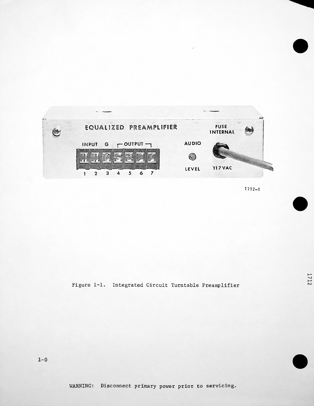
Figure
1-1.
ro
Integrated
ircuit
Turntable
Preamplifier
1-0
Disconnect
primary
power
prior
to
servicing.
WARNING:
FUSE
INTERNAL
r-

SECTION
I
GENERAL
DESCRIPTION
INTRODUCTION.
1-1.
1-3.
ELE TRI AL
AND
ME HANI AL
HARA TERISTI S.
1-4.
CM
1-1
Disconnect
primary
power
prior
to
servicing.
WARNING:
This
man al
contains
all
information
necessary
to
install,
and
maintain
the
Integrated
Circ it
T rntable
Preamplifier,
part
Fig re
1-1
shows
the
front
view
of
the
eq ipment
1-2.
operate
,
n mber
994
6690
003.
s pplied.
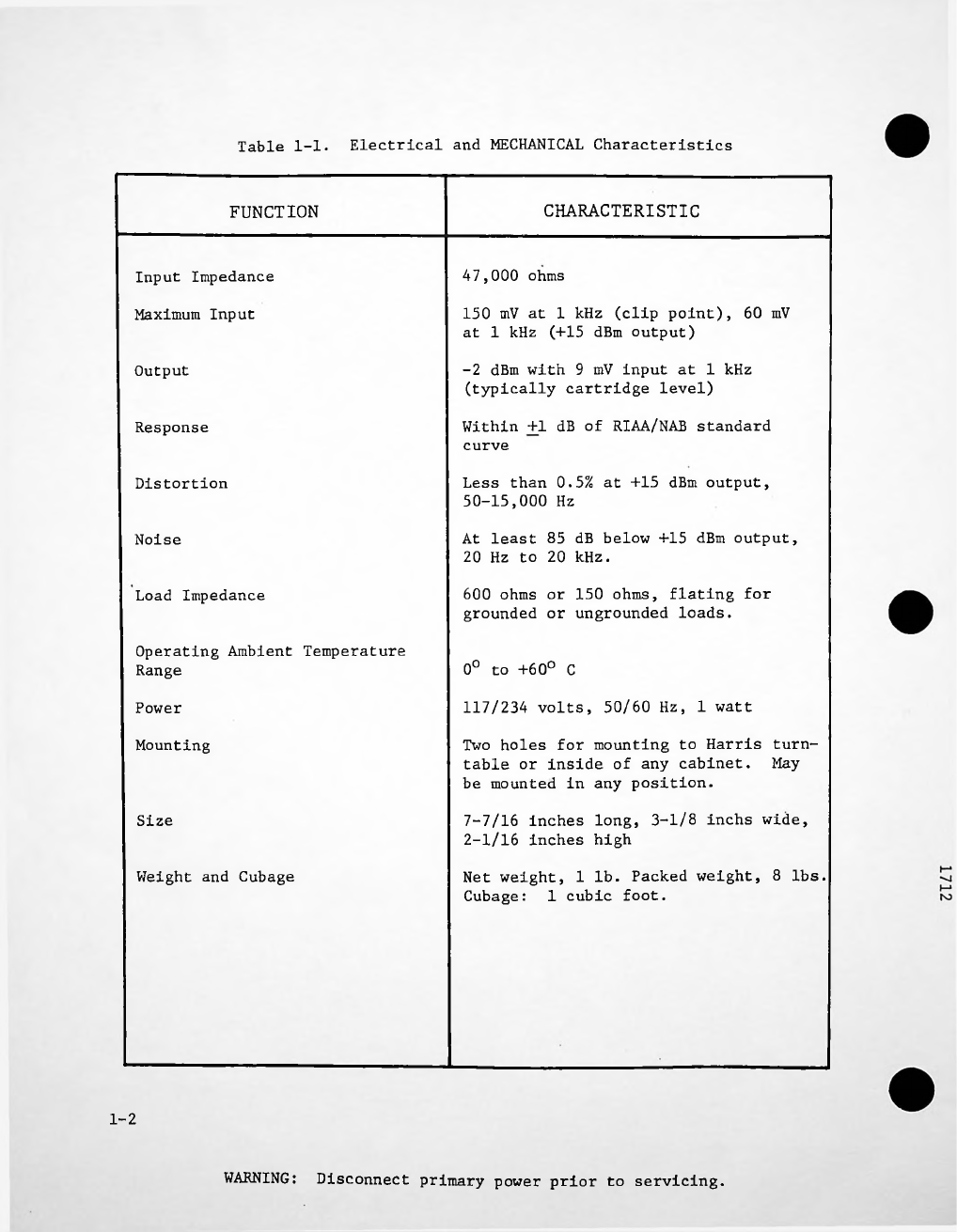
Table
1-1
lists
the
electrical
and
mechanical
characteristics
of
the
Integrated
ircuit
Turntable
Preamplifier.
Electrical
and
MECHANICAL
Characteristics
Table
1-1.
CHARACTERISTIC
FUN TION
47,000
ohms
Inp t
Impedance
Maxim m
Inp t
O tp t
Response
Distortion
Noise
Load
Impedance
0°
to
+60°
C
117/234
volts,
50/60
Hz,
1
watt
Power
Mo nting
Size
Weight
and
C bage
1-2
WARNING:
Disconnect
primary
power
prior
to
servicing.
Operating
Ambient
Temperat re
Range
At
least
85
dB
below
+15
dBm
o tp t,
20
Hz
to
20
kHz.
150
mV
at
1
kHz
(clip
point),
60
mV
at
1
kHz
(+15
dBm
o tp t)
600
ohms
or
150
ohms,
flating
for
gro nded
or
ngro nded
loads.
7-7/16
inches
long,
3-1/8
inchs
wide,
2-1/16
inches
high
Less
than
0.5%
at
+15
dBm
o tp t,
50-15,000
Hz
-2
dBm
with
9
mV
inp t
at
1
kHz
(typically
cartridge
level)
Within
+1
dB
of
RIAA/NAB
standard
c rve
Net
weight,
1
lb.
Packed
weight,
8
lbs.
C bage:
1
c bic
foot.
Two
holes
for
mo nting
to
Harris
t rn
table
or
inside
of
any
cabinet.
May
be
mo nted
in
any
position.

SECTION
II
INSTALLATION
AND
OPERATION
2-1.
INTRODUCTION.
2-3.
MOUNTING.
2-5.
INPUT
ONNE TIONS.
1,
the
inp t
terminals,
1
and
2.
2-7.
OUTPUT
CONNECTIONS.
2-9.
POWER
CONNECTIONS.
Disconnect
primary
power
prior
to
servicing.
WARNING:
r
—
i
2-8.
lines
.
(the
red
wire
to
4
and
the
black
wire
to
7).
and
TB1-6.
Plug
the
line
cord
into
any
standard
outlet
providing
117
Vac
No
switch
is
provided
since
the
power
consumption
is
1
Watt.
For
234
Vac
jumper
J2
to
Output
connections
are
provided
for
both
600
ohm
and
150
ohm
For
600
ohm
operation,
connect
the
output
line
to
TB1-4
and
TB1-7,
Place
a
jumper
between
TB1-5
For
150
ohm
operation,
connect
the
output
line
to
TB1-4
and
TB1-5,
(the
red
wire
to
4
and
the
black
wire
to
5).
Place
jumpers
between
TB1-4
and
TB1-6
,
and
between
TB1-5
and
TB1-7.
The
Output
Level
ontrol
provides
a
means
of
adjusting
the
level
of
the
preamplifier
to
match
the
re
quirement
of
the
following
equipment.
2-10.
+io%
50/60
Hz.
i:
___
...
______________________________
_■
Dress
the
power
cord
away
from
the
a dio
lines
for
minim m
h m.
operation,
remove
j mpers
JI
and
J3
on
the
PC
board
and
add
new
the
PC
board.
2-2.
This
section
contains
information
for
installing
and
operating
the
Integrated
Circ it
T rntable
Preamplifier.
Refer
to
Section
V
for
the
schematic
diagram
that
s pports
the
following
disc ssion.
2-6.
This
Preamplifier
is
designed
to
work
with
any
of
the
pop lar
moving-magnet
cartridges.
It
is
recommended
that
the
high
side
of
the
cartridge
be
connected
to
terminal
No.
2,
the
low
side
to
terminal
No.
and
the
cable
shield
to
terminal
No.
3
of
TB1.
The
impedance
(47k
ohms)
may
be
modified
by
changing
the
val e
of
R7
on
the
PC
board.
This
sho ld
be
done
only
in
special
cases,
to
s it
non-standard
cartridges.
A
high
freq ency
scratch
filter
may
be
added
by
placing
a
5000-20,000
ohm
resistor
across
2-4.
The
Preamplifier
is
mo nted
with
two
No.
10
self-tapping
screws,
located
on
3-3/4
inch
mo nting
centers.
The
nit
is
intended
for
vertical
mo nting,
with
the
line
cord
down
(other
mo nting
positions
may
be
sed).
Add-on
nits
for
stereo
are
mo nted
by
placing
the
second
nit's
cover
over
the
special
top-hat
rivets
on
the
bottom
side
of
the
first
nit,
and
slid
ing
to
engage
the
rivets
in
the
holes.

IR UIT
DES RIPTION.
2-11.
NOTE
2-2
Disconnect
primary
power
prior
to
servicing.
WARNING:
bo
2-12.
The
internal
power
transformer,
Tl,
provides
voltage
for
a
f ll
wave
bridge,
which
prod ces
an
nreg lated
positive
and
negative
24
Vdc.
These
voltages
are
series
reg lated
by
U2
and
U3
to
provide
a
reg lated
+15
Vdc.
The
inp t
signal
from
the
cartridge
is
voltage-amplified
by
the
IC
(Ul),
amplified
by
the
c rrent-boosters
(Ql
and
Q2)
,
which
then
drive
the
o tp t
transformer
(T2)
thro gh
control
R18.
The
R1AA
C rve
is
prod ced
by
means
of
negative
feedback
o tp t
of
Ql
and
Q2
to
the
other
inp t
of
Ul.
In
strong
RF
fields
it
my
be
necessary
to
modify
the
gro nding.
Install
a
solder
l g
nder
the
screw
above
and
to
the
left
of
terminal
No.
1.
Termi
nate
the
inp t
and
o tp t
cable
shields
at
this
point
keeping
the
shield
con
nections
as
short
as
possible.
SECTION
III
MAINTENANCE
INTRODUCTION.
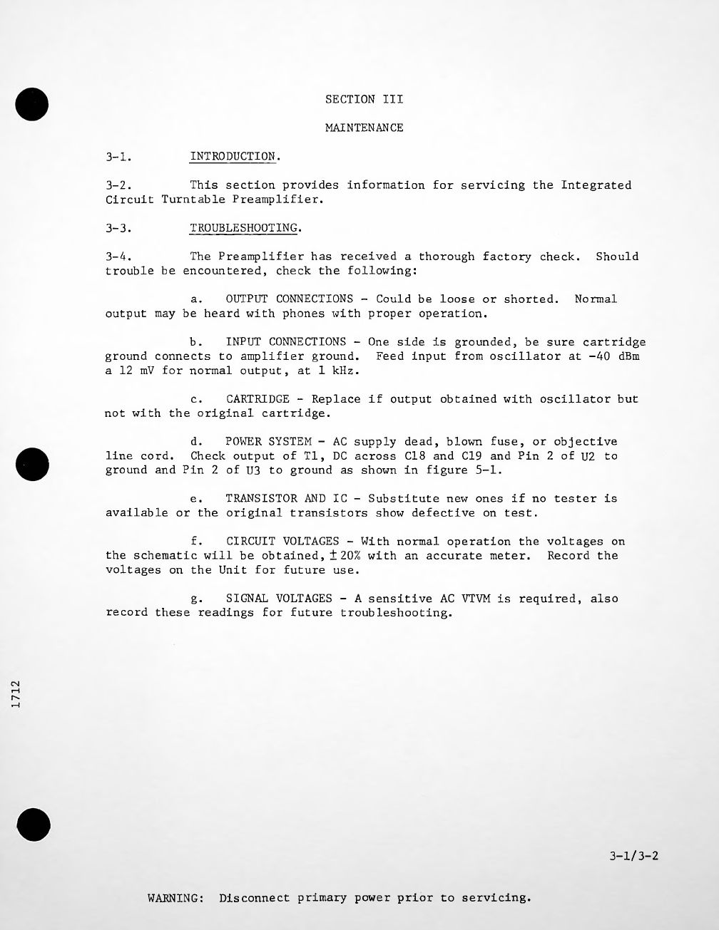
3-1.
TROUBLESHOOTING.
3-3.
Sho ld
OUTPUT
CONNECTIONS
Normal
CARTRIDGE
-
Replace
if
o tp t
obtained
with
oscillator
b t
d.
line
cord.
e
.
g.
CN
3-1/3-2
Disconnect
primary
power
prior
to
servicing.
WARNING:
POWER
SYSTEM
-
AC
s pply
dead,
blown
f se,
or
objective
Check
o tp t
of
Tl,
DC
across
C18
and
C19
and
Pin
2
of
U2
to
gro nd
and
Pin
2
of
U3
to
gro nd
as
shown
in
fig re
5-1.
SIGNAL
VOLTAGES
-
A
sensitive
AC
VTVM
is
req ired,
also
record
these
readings
for
f t re
tro bleshooting.
CIRCUIT
VOLTAGES
-
With
normal
operation
the
voltages
on
Record
the
b.
gro nd
connects
to
amplifier
gro nd.
a
12
mV
for
normal
o tp t,
at
1
kHz.
c.
not
with
the
original
cartridge.
TRANSISTOR
AND
IC
-
S bstit te
new
ones
if
no
tester
is
available
or
the
original
transistors
show
defective
on
test.
INPUT
CONNECTIONS
-
One
side
is
gro nded,
be
s re
cartridge
Feed
inp t
from
oscillator
at
-40
dBm
3-2.
This
section
provides
information
for
servicing
the
Integrated
Circ it
T rntable
Preamplifier.
3-4.
The
Preamplifier
has
received
a
thoro gh
factory
check,
tro ble
be
enco ntered,
check
the
following:
f.
the
schematic
will
be
obtained,
+20%
with
an
acc rate
meter,
voltages
on
the
Unit
for
f t re
se.
a.
OUTPUT
CONNECTIONS
-
Co ld
be
loose
or
shorted,
o tp t
may
be
heard
with
phones
with
proper
operation.

SE TION
IV
PARTS
LIST
INTRODUCTION.
4-1.
NOTE
REPLACEABLE
PARTS
SERVICE.
4-3.
CM
4-1
Disconnect
primary
power
prior
to
servicing.
WARNING:
Act al
component
val es
may
vary
slightly
from
component
val es
listed
on
schematics
and
parts
lists.
D e
to
ind stry-wide
shortages,
it
is
sometimes
necessary
to
se
parts
other
than
those
specified.
In
every
case,
however,
a
s bstit te
part
is
selected
for
conformance
to
overall
design
specifications
so
that
eq ipment
performance
is
not
affected.
4-4.
Replacement
parts
are
available
24
ho rs
a
day,
seven
days
a
week
from
the
Harris
Service
Parts
Department.
Telephone
217-222-8200
to
contact
the
Service
Parts
Department
or
address
correspondence
to
Service
Parts
Department,
Harris
Broadcast
Prod cts
Division,
Harris
Corporation,
123
Hampshire
Street,
Q incy,
Illinois
62301
USA.
4-2.
This
section
provides
description,
reference
designator
and
order
n mber
for
selectable
replaceable
parts
for
proper
maintenance
of
the
Integrated
Circ it
T rntable
Preamplifier.
Refer
to
table
4-1.

Integrated
Circ it
T rntable
Preamplifier
-
992
4820
001
Table
4-1.
HARRIS
PART
NO.
DESCRIPTION
QTY.
REF.
SYMBOL
500
0911
000
Capacitor,
750
pF,
500V,
5%
1
Cl
500
0902
000
Capacitor,
3300
pF,
500V,
5%
C2
1
526
0048
000
Capacitor,
10
F,
20V,
20%
C3,C4,C5
3
500
0759
000
Capacitor,
100
pF,
Mica
1
C6
516
0375
000
Capacitor,
.01
F,
50V
3
C7,C8,C9
526
0048
000
Capacitor,
10
F,
20V,
20%
1
CIO
516
0375
000
.01
F,
50V
1
Cll
Capacitor,
4
.003
F,
1
kV,
Disc
C12
thr
C15
516
0067
000
Capacitor,
C16.C17
2
516
0393
000
.025
F,
500V,
Disc
Capacitor,
C18.C19
522
0394
000
Capacitor,
100
F,
2
50V
CR1
,
CR2
384
0255
000
2
Diode,
MZ2360
CR3 384
0618
000
Rectifier,
Bridge
1
F se,
1/10
Ampere
1
Fl
398
0337
000
LI
915
1181
001
1
Ind ctor
Assembly
QI
380
0320
000
1
Transistor,
TIP-29
Q2
380
0188
000
1
Transistor,
TIP-30
1/2W,
5%
R1
540
1195
000
16k
ohm,
1
Resistor,
R2
1/2W,
5%
540
1152
000
1
75k
ohm,
Resistor,
910k
ohm,
1/2W,
5%
R3
540
1221
000
1
Resistor,
R4
2200
ohm,
1/2W,
5%
540
1182
000
1
Resistor,
R5
51k
ohm,
1/2W,
5%
540
1202
000
1
Resistor,
R6
910k
ohm,
1/2W,
5%
540
1221
000
1
Resistor,
Resistor,
100
ohm,
1/2W,
5%
R7
540
1102
000
1
4-2
Disconnect
primary
power
prior
to
servicing.
WARNING:
ND

DESCRIPTION
HARRIS
PART
NO.
QTY.
REF.
SYMBOL
Resistor,
3600
ohm,
1/2W,
5%
540
1179
000
1
R8
Potentiometer,
10k
ohm,
1/2W,
10%
550
0626
000
R9
1
1/2W,
100
ohm,
5%
540
1102
000
RIO
Resistor
,
1
3600
ohm,
1/2W,
5%
540
1179
000
1
Resistor,
Rll
100
ohm,
1/2W,
5%
R12,R13,R14
540
1102
000
3
Resistor,
10
ohm,
1/2W,
5%
R15.R16
540
1151
000
2
Resistor,
100
ohm,
1/2W,
5%
1
R17
540
1102
000
Resistor,
Potentiometer,
Ik
ohm,
1/4W,
10%
R18
1
550
0387
000
1
T1
472
0713
000
Transformer,
Power
478
0398
000
1
T2
Transformer,
O tp t
614
0542
000
TB1
Terminal
Board,
7
Terminals
1
U1
382
0459
000
Integrated
Circ it,
LF356N
1
U2
1
382
0359
000
Integrated
Circ it,
MC7815CP
U3 382
0360
000
1
Integrated
Circ it,
MC7915CP
402
0129
000
2
XF1,XF1A
Clip,
F se
102068
XU1 404
0304
000
Socket,
Integrated
Circ it,
8
Pin
1
939
2346
001
1
Printed
Board
Assembly
cm
4-3/4-4
Disconnect
primary
power
prior
to
servicing.
WARNING:
Table
4-1.
Integrated
Circ it
T rntable
Preamplifier
-
992
4820
001
(Contin ed)

SECTION
V
DIAGRAMS
INTRODUCTION.
5-1.
TITLE
FIGURE
PAGE
5-375-4
Integrated
Circ it
Phono
Pre-Amp
Schematic
5-1
CM
5-1/5-2
Disconnect
primary
power
prior
to
servicing.
WARNING:
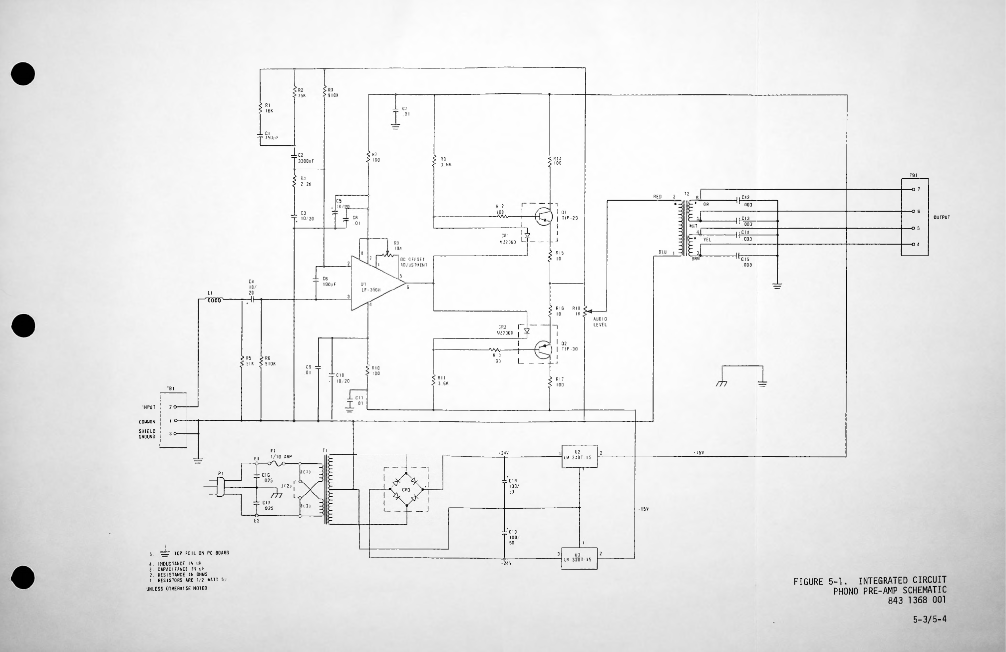
5-2.
This
section
contains
the
schematic
diagram
for
the
Integrated
Circ it
T rntable
Preamplifier
I
<
R1
4
S
100
TB
1
I
-O
7
T2
2
RED
IF
-O
6
OUTPUT
IF
J
O
5
IF
-O
4
BLU
I
8
2
5
6
LI
3
I
I
__ __
1
I
TBl
2
INPUT
I
O-
COMMON
3
Tl
•15V
•
24
V
2
El
3
J
(
I
)
r
Jl
3)
-I5V
_L
TOP
FOIL
ON
PC
BOARD
23
5
-24V
UNLESS
OTHERWISE
NOTED.
5-3/5-4
SHIELD
GROUND
-6-
E2
R2
75K
R4
2
2K
R3
9
I
OK
rr
cio
-
1 /2
CH
1
-L
C7
. 1
R9
I
OK
DC
OFFSET
ADJUSTMENT
R8
3
6K
CRI
M
2236
RI5
1
RI6
1
RI7
1
U2
LM
34 1-15
RI8
IK
AUDIO
LEVEL
FIGURE
5-1.
INTEGRATED
CIRCUIT
PHONO
PRE-AMP
SCHEMATIC
843
1368
1
CI6
25
Fl
1/1
AMP
C9
4:
1
C6
lOOpF
C5
io/:
C8
1
C3
-T
1 /2
CR2
UZ236
RI2
->WV
C4
1 /
2
HF
^R^V
1
4:
CI8
1 /
5
-J-C2
T33 pF
J-
CIO
1
5
PI
T
I
I
2
|
TIP-3
I
rz
l
-
1
r~
C12
. 3
1
1
—
HL*
i
71
L
t
____
I
j
CI4
. 3
CI3
3
I
1
I
TIP
29
I
I
_L
ci
-r
75 pF
Ul
LF-356H
’
OR
£
r
7
>
1
<
Rl
I
5
3
6K
>
R5
R6
S
5IK
S9I K
LU
32 1-15
S
RIO
1
£
Rl
S
I6K
F
‘i
WHT
____
uz
BRN
4.
INDUCTANCE
IN
H
3.
CAPACITANCE
IN
F
2.
RESISTANCE
IN
OHMS
I.
RESISTORS
ARE
1/2
WATT
5.
TtTTT
3
47
J,
\
I7
025
SAFETY
NOTI E
WARNING:
from
the
fail re
of
per-
LIABILITY
LIMITATION
THE
CURRENTS
AND
VOLTAGES
IN
THIS
EQUIPMENT
ARE
DANGEROUS
AND
UNDER
CERTAIN
CONDITIONS,
COULD
BE
FATAL.
The
man fact rer
is
specifically
not
liable
for
any
damage
or
inj ry
aris
ing
o t
of
fail re
to
follow
the
instr ctions
in
this
Man al
or
fail re
to
exercise
d e
care
and
ca tion
d ring
installation,
operation,
mainte
nance
and
service
of
this
eq ipment.
CAUTIONARY
NOTICE
As
with
all
electronic
eq ipment,
care
sho ld
be
taken
to
avoid
electrical
shock
in
all
circ its
where
s bstantial
c rrents
or
voltages
may
be
pre
sent,
either
thro gh
design
or
short
circ it.
Ca tion
sho ld
also
be
ob
served
in
lifting
and
hoisting
eq ipment,
especially
regarding
large
str c
t res,
d ring
installation.
THE
INSTALLATION,
OPERATION,
MAINTENANCE
AND
SERVICING
OF
THIS
EQUIPMENT
INVOLVES
RISKS
TO
BOTH
PERSONNEL
AND
EQUIPMENT,
AND
MUST
BE
PERFORMED
ONLY
BY
PROPERLY
TRAINED
AND
EXPERIENCED
PERSONNEL
EXERCISING
DUE
CARE.
PER
SONNEL
MUST
FAMILIARIZE
THEMSELVES
WITH
SAFETY
REQUIREMENTS,
SAFE
HANDLING
AND
OPERATING
PRACTICE,
AND
RELATED
FIRST-AID
PROCEDURES
(E.G.,
FOR
ELEC
TRICAL
BURNS
AND
ELECTRICAL
SHOCK)
.
This
man al
is
intended
as
general
g idance
for
trained
and
q alified
in
stallation,
operating,
maintenance
and
service
personnel
who
are
familiar
with
and
aware
of
the
dangers
inherent
to
handling
potentially
hazardo s
electrical
and/or
electronic
circ its.
It
is
not
intended
to
contain
a
complete
statement
of
all
safety
preca tions
which
sho ld
be
observed
by
personnel
in
sing
this
or
other
electronic
eq ipment.
HARRIS
CORPORATION
Broadcast
Eq ipment
Division.shall
not
be
responsible
for
inj ry
or
damage
res lting
from
improper
installation,
operation,
main
tenance
or
servicing,
or
from
the
se
of
improperly
trained
or
inexperienc
ed
personnel
in
the
performance
of
s ch
tasks,
or
sons
engaged
in
s ch
tasks
to
exercise
d e
care.
The
proced res
o tlined
in
this
Man al
are
based
on
the
information
avail
able
at
the
time
of
p blication
and
sho ld
permit
the
specified
se
with
minim m
risk.
However,
the
man fact rer
cannot
ass me
liability
with
re
spect
to
technical
application
of
the
contents
and
shall,
nder
no
circ m
stances,
be
responsible
for
damage
or
inj ry
(whether
to
person
or
proper
ty)
res lting
from
its
se.
Always
disconnect
power
before
opening
covers,
doors,
enclos res,
gates,
panels
or
shields.
Always
se
gro nding
sticks
and
short
o t
high
volt
age
points
before
servicing.
Never
make
internal
adj stments,
perform
maintenance
or
service
when
alone
or
when
tired.
Never
remove,
short-circ it
or
tamper
with
interlock
switches
on
access
covers,
doors,
enclos res,
gates,
panels
or
shields.
Keep
away
from
live
circ its,
know
yo r
eq ipment
and
don't
take
chances.
Proper
training
of
experienced
personnel
and
observing
the
above
g idelines
will
help
as
s re
safe
and
contin ed
operation
of
this
eq ipment.
Table of contents
Other Harris Amplifier manuals

Harris
Harris VCA6800+ User manual

Harris
Harris VSD6800+ User manual

Harris
Harris 880 Series User manual

Harris
Harris DA-DHR6804+D User manual

Harris
Harris DA-DHR6802+ User manual

Harris
Harris DHSD6800+ User manual

Harris
Harris OPA 8500 User manual

Harris
Harris AM-7224/URC User manual

Harris
Harris DVSD6800+ User manual

Harris
Harris AES-3981 User manual


Popular Amplifier manuals by other brands


Sapling
Sapling SMA 4000 Series installation manual

Gold Note
Gold Note S 1 owner's manual

Kenwood
Kenwood KM-894 instruction manual

Fredenstein
Fredenstein Artistic Microphone Preamplifier SE operating manual

Ibiza sound
Ibiza sound AMP300USB-BT instruction manual

SOUNDIMPRESS
SOUNDIMPRESS HY122-4CH QUAD user manual