Harris NetWave User manual

Broadcast
Console
Operations
&
Technical
Manual
PRE75-54PRE75-54
PRE75-54PRE75-54
PRE75-54
Revision A • 6/06
BroadcastCommunicationsDivision
www.broadcast.harris.com
8-input console: 99-1600-08
16-input console: 99-1600-16
24-input console: 99-1600-24

Revision A • 6/06
HARRIS CORPORATION
ii

Revision A • 6/06
HARRIS CORPORATION
iii
Contents
CE Declaration of Conformity........................ iv
Safety Instructions ......................................... v
Hazard/Warning Label Identification............. v
1 - INTRODUCING NETWAVE
Product Overview ....................................... 1-1
Specifications .............................................. 1-8
Warranty................................................... 1-10
2 - INSTALLATION
Console Installation..................................... 2-2
Cabling andWiring ................................... 2-18
Mic Remote Control Logic Example.......... 2-27
Basic Peripheral Logic Example................ 2-28
Complex Peripheral Logic Example .......... 2-29
VistaMax Network Connections ................ 2-30
3 - USING NETWAVE
Console Overview .........................................3-1
Dual Fader Panel..........................................3-3
Dual Router Panel........................................3-4
Monitor Control Panel..................................3-5
Reflective Console Display............................3-9
NetWaveApplications ................................3-10
Stand Alone Operation ..........................3-10
Telco/Codec Operation..........................3-11
4 - LINKING NETWAVE
Linked NetWave Consoles ............................4-1
Verifying SoftwareVersions .....................4-1
Linked NetWave Features .......................4-2
Linked NetWave Setup.................................4-2
Signal Setup Details .....................................4-9
Macro Files ................................................4-10
5- SERVICING NETWAVE
Parts and Repair Services............................ 5-1
Spare and Replacement Parts...................... 5-2
ConsoleTroubleshooting.............................. 5-3
Control Panel Service .................................. 5-3
Console Display Service............................... 5-5
48Volt Supplies .......................................... 5-6
Product Description .................................... 5-7
6 - NETWAVE ACCESSORIES
Furniture and Cabinetry .............................. 6-1
Accessory Panels ......................................... 6-1
Headphone Distribution Amp ..................... 6-3
ESE/SMPTE Master Clock ......................... 6-4
NetWave Upgrade Kits................................ 6-5
Mic Remote Panel Cables ............................ 6-6
INDEX
A - C .....................................................Index-1
C - I.......................................................Index-2
I - P ......................................................Index-3
P -W ....................................................Index-4

Revision A • 6/06
HARRIS CORPORATION
iv
Declaration of Conformity

Revision A • 6/06
HARRIS CORPORATION
v
1. RR
RR
Read Aead A
ead Aead A
ead All Instrll Instr
ll Instrll Instr
ll Instrucuc
ucuc
uctionstions
tionstions
tions..... Read all safety and operating
instructions before operating the product.
2. RR
RR
RetainAetainA
etainAetainA
etainAllInstrllInstr
llInstrll Instr
llInstrucuc
ucuc
uctionstions
tionstions
tions..... Retainallsafetyandoperating
instructions for future reference.
3. HH
HH
Heed Aeed A
eed Aeed A
eed Allll
llll
llWW
WW
Warar
arar
arningsnings
ningsnings
nings.....Youmustadhere toall warnings
on the product and those listed in the operating
instructions.
4. FF
FF
Folloollo
olloollo
ollow Aw A
w Aw A
w All Instrll Instr
ll Instrll Instr
ll Instrucuc
ucuc
uctionstions
tionstions
tions..... Follow all operating and
product usage instructions.
5. HH
HH
Heaea
eaea
eatt
tt
t..... This product must be situated away from any
heat sources such as radiators, heat registers, stoves,
or other products (including power amplifiers) that
produce heat.
6. VV
VV
Venen
enen
entilatila
tilatila
tilation.tion.
tion.tion.
tion. Slots and openings in the product are
providedforventilation.Theyensurereliableoperation
of the product and keep it from overheating.Do not
block or cover these openings during operation.Do
not place this product into a rack unless proper
ventilation is provided and the manufacturer’s
recommended installation procedures are followed.
7. WW
WW
Waa
aa
att
tt
ter and Mer and M
er and Mer and M
er and Moisturoistur
oistur
oistur
oisturee
ee
e..... Do not use this product near
water such as a bathtub, wash bowl, kitchen sink, or
laundry tub,in a wet basement, or near a swimming
pool or the like.
8. AA
AA
Attachmenttachmen
ttachmenttachmen
ttachmentsts
tsts
ts..... Do not use any attachments not
recommended by the product manufacturer as they
may cause hazards.
9. PP
PP
Poo
oo
oww
ww
wer Ser S
er Ser S
er Sourour
ourour
ourcc
cc
ceses
eses
es.....Youmustoperatethisproductusing
the type of power source indicated on the marking
label and in the installation instructions.If you are not
sure of the type of power supplied to your facility,
consultyourlocalpowercompany.
10. GG
GG
Grr
rr
rounding and Pounding and P
ounding and Pounding and P
ounding and Polarolar
olarolar
olarizaiza
izaiza
ization.tion.
tion.tion.
tion. This product is
equippedwithapolarizedACplugwithintegralsafety
ground pin. Do not defeat the safety ground in any
manner.
11. PP
PP
Poo
oo
oww
ww
werCerC
erCerC
erCoror
oror
ord Pd P
d Pd P
d Prr
rr
rotot
otot
otecec
ecec
ection.tion.
tion.tion.
tion.Powersupplycordsmustbe
routed so that they are not likely to be walked on nor
pinched by items placed upon or against them.Pay
particular attention to the cords at AC wall plugs and
convenience receptacles,and at the point where the
cord plugs into the product.
12. LighLigh
LighLigh
Lightningtning
tningtning
tning..... For added protection for this product,
unplug it from the AC wall outlet during a lightning
storm or when it is left unattended and unused for
long periods of time.This will prevent damage to the
product due to lightning and power line surges.
13. OO
OO
Ovv
vv
verer
erer
erloadingloading
loadingloading
loading..... Do not overload AC wall outlets,
extensioncords,orintegralconvenienceoutletsasthis
can result in a fire or electric shock hazard.
14. OO
OO
Objecbjec
bjecbjec
bject and Liquid Et and Liquid E
t and Liquid Et and Liquid E
t and Liquid Enn
nn
ntrtr
trtr
tryy
yy
y..... Never push objects of any
kind into this product through openings as they may
touch dangerous voltage points or short out parts,
whichcouldresultinafireorelectricshock.Neverspill
liquid of any kind on the product.
15. AA
AA
Acccc
cccc
ccessoressor
essoressor
essoriesies
iesies
ies..... Donotplacethisproductonanunstable
cart, stand, tripod, bracket, or table.The product may
fall,causingseriousinjurytoachildoradultandserious
damagetothe product.Anymountingoftheproduct
must follow manufacturer’s installation instructions.
Safety Instructions16. PP
PP
Prr
rr
roo
oo
oducduc
ducduc
duct and Ct and C
t and Ct and C
t and Carar
arar
art Ct C
t Ct C
t Combinaombina
ombinaombina
ombination.tion.
tion.tion.
tion.Movethisproduct
with care. Quick stops, excessive force, and uneven
surfaces may cause the product and the cart
combination to overturn.
17. SS
SS
Serer
erer
ervicingvicing
vicingvicing
vicing..... Refer all servicing to qualified servicing
personnel.
18. DD
DD
Damage Ramage R
amage Ramage R
amage Requirequir
equirequir
equiring Sing S
ing Sing S
ing Serer
erer
ervicvic
vicvic
vicee
ee
e..... Unplug this product
fromthewallACoutletandreferservicingtoqualified
service personnel under the following conditions:
a. When the AC cord or plug is damaged.
b. If liquid has been spilled or objects have fallen into
the product.
c. If the product has been exposed to rain or water.
d. If the product does not operate normally (following
operating instructions).
e. If the product has been dropped or damaged in any
way.
f. When the product exhibits a distinct change in
performance.This indicates a need for service.
19. RR
RR
Replaceplac
eplaceplac
eplacemenemen
emenemen
ement Pt P
t Pt P
t Parar
arar
artsts
tsts
ts..... When replacement parts are
required, be sure the service technician has used
replacement parts specified by the manufacturer or
thathavethesamecharacteristicsastheoriginalparts.
Unauthorized substitutions may result in fire,electric
shock, or other hazards.
20. SS
SS
Safaf
afaf
afetet
etet
ety Cy C
y Cy C
y Check.heck.
heck.heck.
heck.Uponcompletionofanyrepairstothis
product,ask the service technician to perform safety
checks to determine that the product is in proper
operating condition.
21. CC
CC
Cleaningleaning
leaningleaning
leaning..... Do not use liquid or aerosol cleaners.Use
only a damp cloth for cleaning.
WW
WW
WARNINGARNING
ARNINGARNING
ARNING—Thisequipmentgenerates,uses,andcanradiateradiofrequencyenergy.Ifnotinstalledandused inaccordancewiththe instructionsin this
manual it may cause interference to radio communications. It has been tested and found to comply with the limits for a Class A computing device
(pursuanttoSubpartJof Part15FCCRules),whicharedesigned toprovide reasonable protection against suchinterferencewhen operatedinacommer-
cial environment. Operation of this equipment in a residential area is likely to cause interference,in which case the user, at his own expense,will be
required to take whatever measures may be required to correct the interference.
Hazard/Warning Label Identification
The LighLigh
LighLigh
Lightning Ftning F
tning Ftning F
tning Flashlash
lashlash
lashWW
WW
Withith
ithith
ith
AA
AA
Arr
rr
rrr
rr
roo
oo
owhead symbwhead symb
whead symbwhead symb
whead symbolol
olol
ol,within an
equilateral triangle,alerts the user to
the presence of uninsulated
dangerous voltage within the
product’s enclosure that may be of
sufficient magnitude to constitute a
risk of electric shock.
The EE
EE
Exx
xx
xclamaclama
clamaclama
clamation Ption P
tion Ption P
tion Poinoin
oinoin
oint symbt symb
t symbt symb
t symbolol
olol
ol,
within an equilateral triangle,alerts the
user to the presence of important
operating and maintenance (servicing)
instructions in product literature and
instruction manuals.
RISK OF ELECTRIC SHOCK
DO NOT OPEN
CAUTION
WARNING: SHOCK HAZARD - DO NOT OPEN
AVIS:RISQUE DE CHOC ELECTRIQUE - NE PAS OUVRIR
CAUTION:TO REDUCETHE RISK OF ELECTRIC SHOCK DO NOT
REMOVE ANY COVER OR PANEL.NO USER SERVICEABLE PARTS
INSIDE.REFER SERVICINGTO QUALIFIED SERVICE PERSONNEL.
WARNING:TO REDUCETHE RISK OF FIRE OR ELECTRIC
SHOCK,DO NOT EXPOSETHE POWER SUPPLY OR CONSOLE
TO RAIN OR MOISTURE.

Revision A • 6/06
HARRIS CORPORATION
vi

Revision A • 6/06
HARRIS CORPORATION
1-1
1
Thanks for joining the growing ranks of
broadcasters employing Harris Corporation prod-
ucts designed by PR&E. Our mission: provide the
finestqualityproducts,systems,documentationand
after-salesupport.
To obtain the maximum benefit from the
NetWave’s capabilities, read through the chapters
on
Installation
and
Operation
prior to the actual
product installation.
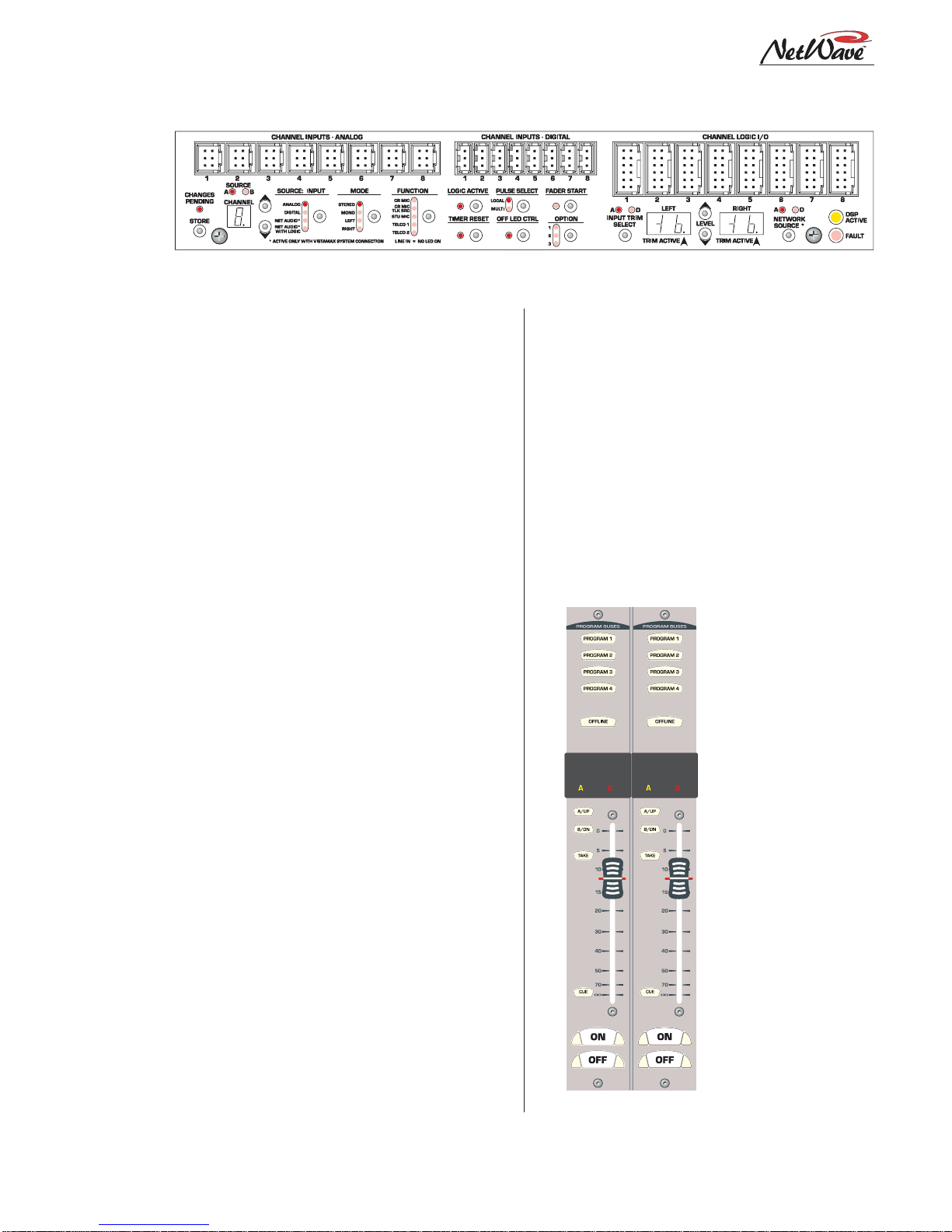
NetWave consoles have these parts:
•Main Frame: with 8, 16 or 24 channel slots
•Monitor & Output Card: one per console
•DSP & I/O Card: one on 8-input frames; two
on 16-input frames; three on 24-input frames
•Monitor Panel: one per console
•Dual Fader Panel: four on 8-input frames;six
on 16-input frames; nine on 24-input frames
•Reflective Display: clock,timerand twometers
arestandard,an additional twometerscan be
added to the NetWave-16 and NetWave-24
•Dual Width Blank Panel: two standard on
NetWave-16;three on NetWave-24(coverthe
unpopulated channel slots)
•48-volt Supply: an in-line supply is standard
on the NetWave-8 and NetWave-16; a rack-
mountsupplyis standard on theNetWave-24
(optional on the other frame sizes)
•Installation Materials: installation kit; Net-
Wave CD-ROM;NetWave Quick Guide
•Toolkit (optional): 76-1901 toolkit
•Printed Manual (optional): 75-54 NetWave
Installation & Operation manual
Introducing
NetWave
NetWave-16 Console

Revision A • 6/06
HARRIS CORPORATION
1-2
1 Introducing NetWave
Envoy card frames and RMX
d
and BMX
d
con-
soles,comesstandardwith the NetWave-24;while
anin-linesupply (50-27) comesstandardwith the
NetWave-8and 16 framesizes.A 99-1205 supply
can also be used on the smaller NetWave frames.
An optional 90-1995 Power Coupler is avail-
able to allow any NetWave console to be redun-
dantly powered by coupling in a second matching
48-volt supply.
The NetWave has an all-aluminum chassis,
which fully contains all circuit board electronics,
for strength and RFI immunity. To ensure silent
operation,all NetWave parts (console frame,con-
trol panels, console display and power supplies)
areconvectioncooled—meaningno fans,andcom-
pletely silent operation.
All user audio and logic connections are made
fromthetop rear oftheframe. Connector accessis
via a removable flip-open cover which hides the
cabling and connectors during normal operation.
NETWAVE CONSOLE CONNECTIONS
•Monitor & Output Card:
» Four stereo Program bus outputs (each with
separate analog andAES digital outputs)
» Three stereoanalogcontrol room outputs (for
aroom monitorampand forseparate hostand
guest headphone amps)
» Three stereo analog studio outputs (for a stu-
dio monitor amp and for separate host and
guest headphone amps)
» Two stereo analog External Monitor inputs
» Two mono analog Mix-Minus outputs
Product Overview
NetWave is a low-profile, digitally-controlled,
VistaMax-compatible audio console that sits on
the countertop. Three frame sizes are available,
with 8, 16 or 24 channel slots.
Each NetWave operates as a stand-alone con-
sole but, for maximum flexibility and usability,
can be tied into any VistaMax system (running
500-series code) by installing the optional Link
Activation Kit (99-1425). The kit activates the
built-inVistaMaxLinkwhich,via a singleCAT-5e
cable,tiestheconsoleto aVistaMaxor EnvoyHub
card to allow any system source (audio signals or
audio signals with logic) to be routed to any Net-
Wavechannel andto the ExternalMonitor inputs.
TheVistaMaxLinkalso sends anumber of Net-
Wave signals to theVistaMax system including:
oneinputfromeachchannel (either the local ana-
log or digital input can be chosen); each program
bus output;both mix-minus outputs (which have
both a clean feed and an IFB feed); the two chan-
nel Telco record output; and the stereo cue bus.
These signals can then be routed to anyVistaMax
system destination as required.
To further enhance a“Linked”console, an op-
tionalDualFader panel upgrade,theDual Router
Kit (99-1424), is also available.This kit adds in
VistaMax source selection ability to both chan-
nels on any Dual Fader panel.
The ReflectiveDisplay,withtwostereobargraph
meters (PGM 1 and auxiliary), a clock which can
be slaved to an ESE or a SMPTE master clock
and an Event Timer, is integrated into the frame
behindthe control panels.Quadmeterdisplaykits
are available for the NetWave-16 (99-1990-16Q)
and for the NetWave-24 (99-1990-24Q) to add
dedicated Program 2 and Program 3 meters.
Two 48-volt power supplies are used with Net-
Wave consoles: a rack mount supply (99-1205),
which is the same one used withVistaMax and
Monitor and Output Card Connections
Revision A • 6/06
HARRIS CORPORATION
1-3
1 Introducing NetWave
» Separate control room and studio logic con-
nectors (warning interface output, logic I/O
for dim and mute control, talk logic output)
•DSP & I/O Cards:
» Sixteen stereo/dual mono audio inputs (eight
analog and eight digital), assignable as the A
orBsource fortheeight channelcontrolstrips
associated with that card
» Eight channel logic connectors, assignable to
either the A or B source for the eight channel
control strips associated with that card
•Other Connections:
» One 1/4" TRS jack for the board operator
headphones, left side panel
» One RJ-45 VistaMax Link connector for a
CAT-5e cable (requires the optional Link Ac-
tivation Kit be installed)
» One keyed connector for the 48-volt power
supply supplied with the console
» Four,eight or twelve internalRJ-45sockets to
supply power and signals to the Dual Fader
panels
» Four, eight or twelve internal and rear panel
LAN passthru RJ-45 sockets for standard
CAT-5 cabling to connect the optional Dual
Router Kits to theVistaMax LAN
» One ESE or SMPTE master clock input on
the clock-timer board
» One Timer Reset output, for a studio event
timer, on the clock-timer board
MAIN COMPONENT DESCRIPTIONS
NetWave
board operators use three parts: the
Dual Fader panels; the Monitor panel; and the
ReflectiveConsoleDisplay.Eachis covered inthis
sectionalongwithdescriptions for the other parts
making up the console: 48-volt power supplies,
the Monitor & Output card, the DSP & I/O card,
theVistaMax Link and the optional upgrade kits.
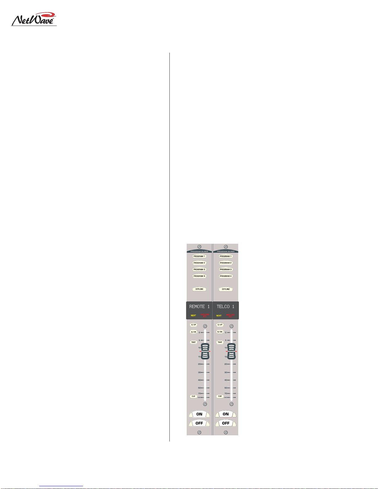
NetWaveDualFaderPanels
Each Dual Fader panel has two channel control
strips.Each strip has the following features:sepa-
rate channel on and off
buttons; a 100mm fader
for channel level control;
cue on/off button; A and
B source selector buttons
withaTake button;active
source illuminated label;
and five bus assignment
buttons (four Program
and one Offline).
Channelcontrolis digi-
tal,so no audio ever trav-
els through the Dual
Fader panel. In fact, a
Dual Fader panel can be
swapped“hot”without af-
fecting either channel’s
audioperformance.
Each Dual Fader panel
plugs into a DSP & I/O
card using a single red
Dual Fader Panel
DSP and I/O CardConnectors and Channel Setup Controls
Revision A • 6/06
HARRIS CORPORATION
1-4
1 Introducing NetWave
CAT-5 cable. Since each DSP & I/O card carries
eight audio channels,up to four Dual Fader pan-
els are plugged into each DSP & I/O card.
Each Dual Fader channel control strip has two
audio inputs and one logic I/O connector associ-
ated with it on the DSP & I/O card. Since each
channel strip has two possible sources (A and B),
which audio input is used for each source is as-
signedduringconsole setup.Inthe standard,non-
linked,NetWave console the two possible inputs
are the local analog input or the local digital in-
put assigned to that channel on the DSP & I/O
card.When the NetWave is linked to aVistaMax
system, there are three selections per source: the
local analog input, the local digital input, or a
routedVistaMax source.
The operating parameters for each source, on
each channel, are independently set during con-
sole setup through a common group of setup but-
tons and LEDs on each DSP & I/O card (shown
in the illustration on the previous page). These
controls set the parameters used when theA and
the B source is selected.The parameters include:
input type (is the input a control room mic, a stu-
dio mic, a line input or aTelco input?); whether
logicisbe associated with that input;whetherthe
event timer is reset at channel on; whether fader
start is active; etc. The parameter settings are
stored in nonvolatile RAM.
The channel strip’sA and B select buttons are
used along with the Take button to choose the
active source for that channel.When theA source
is active,yellow LEDs backlight the A source la-
belundera smoked polycarbonate windowabove
theA button,and the A button is lit.When the B
source is active,red LEDs backlight the B source
label above the fader and the B button is lit.
Setting a channel source to use the logic I/O
meansthechannel can remotely controlaperiph-
eral device (mic control panel, CD player, com-
puter playback system, etc.) and that peripheral
can also control the channel.The logic I/O pro-
vides fully independent parallel logic functions
that: outputs start and stop pulses to line devices
(on and off tallies to mic panels);receives channel
on, off, cue and reset/ready commands from line
devices (on, off, cough and talkback commands
from mic panels).
Dual Router Channels
The optional Dual Router Kit changes the A/B
selector buttons on both channels of any Dual
Fader panel into VistaMax source selector Up/
Down buttons. To use this functionality, the
console’sVistaMax Link must be active.
Dual Fader panels that have the Dual Router
Kit installed are easily identified by the two 10-
character signal name displays under the top half
ofthesmoked polycarbonate lensabovethefader.
The display normally shows the name of the cur-
rent VistaMax source
feeding that channel.
But, when finding the
next source by pressing
an Up or Down button,
the displayed name
switches to show a po-
tential Next Source for
that channel.The yellow
Next label above the Up
button lights while the
NextSourcename isdis-
played.Holding down,or
repeatedly tapping the
Up or Down button,
steps alphanumerically
throughthelist ofpoten-
tial Next Source names
available on that chan-
nel.
Once the desired
source name is shown,
Dual Router Panel

Revision A • 6/06
HARRIS CORPORATION
1-5
1 Introducing NetWave
pressingtheTakebutton selectsthat source—when
the channel is off. New routed sources cannot be
taken when the channel is on (the On button
flashesthreetimes toindicatethe nextsourcecan-
not be taken while the channel is on). But, a next
source can be pre-selected and then taken once
the channel is turned off.
Which sourcesareseen when theUpand Down
buttons are pressed on the router channel is set
using theVistaMax Control Center (VMCC) soft-
ware,vers 1.1 or later. Each channel could be as-
signedanywherefromonesourceuptoeveryavail-
ablesourcein theVistaMaxsystem in its selection
list. In regular use, the signal list is kept short to
make it easy for board operators to easily find
desired sources. If a board operator needs to se-
lected a source that is not shown, pressing both
the Up and Down buttons together turns on the
Include All function, lighting up the red Include
All label. Every source available to the console’s
parent device is now displayed.Pressing both Up
andDownbuttons together again turnsoffthe In-
clude All function.
TheVMCC 1.1 software is included on the Net-
Wave CD-ROM (99-5001) that comes with the
console.
To integrate the NetWave with a VistaMax or
Envoy card frame, theVistaMax devices must be
running 500-series code. The current operating
system code build can be viewed by opening the
release.txt file on the parent card frame or
by using Community Monitor, another program
included on the NetWave CD-ROM.
MonitorPanel
This standardpanelisdividedintothreesections
separated by double graphic lines. From left to
right the sections, divided by main function, are:
Aux Meter control; Control Room control; and
Studio control.
Aux Meter Section
The topofallthreesectionshaveexclusiveaction
sourceselector buttonsto selectone monitorsignal
fromthe PGM1thru4busesandthe twoExternal
Monitor inputs. In the Aux Meter section, the
buttons select which signal feeds the right-most
meter in the Reflective Display, with the selected
source name shown below the Aux Meter.
Note that the Aux Meter is normally set to
alternatelydisplaythecue levelswhilecueis active
(when the cue label is lit, Cue is displayed below
the meter and the cue level is shown).
Operating System Code build,
as shown in the release.txt file
Monitor Control Panel

Revision A • 6/06
HARRIS CORPORATION
1-6
1 Introducing NetWave
SeveralControlRoomcontrolsare locatedbelow
the meter selector buttons in this section of the
panel. They are covered in the Control Room
Section that follows.
Control Room Section
The middle of the panel has the control room
monitorsource selectorbuttonsand thetwo faders
to control the room monitor speaker level and the
operator headphone output level.
Anyonesourcecanbeselectedtofeedallcontrol
room monitor outputs.The active source button
lights to indicate its selection.
A cue speaker, at the left end of the console
display, is level controlled by the cue pot in the
middle of the left-hand section. A cue indicator
(yellow) lights while cue is active.
A talkback pot controls the level of incoming
talkbackthatfeeds the cuespeakerindependently
of the cue volume pot. A Talk to Control Room
indicator (red) lights while a studio microphone
is talking to the control room.
A control room monitor output fader and the
operator headphone output fader are at the bot-
tom of the center section.
The signal mode for both the control room and
studio outputs is set by the Monitor Mode but-
tons in the left-hand section (below the cue and
talkback pots). The L and R buttons control
whether the monitor signal for all outputs is ste-
reo (when neither button is lit), left only (when L
is lit), right only (when R is lit) or a mono sum
signal (when L and R are both lit) where the left
and right signals are summed together to feed all
monitor outputs.
Just below the R mode button is the AutoCue
button.When lit, the operator’s headphone out-
putautomaticallyswitchesto feedthecue businto
the operator’s headphones while cue is active.
When unlit,cue activity does not affect the board
operator’s headphone audio. AutoCue has two
modes of operation (set by switch DS1-3 on the
Monitor& Outputcard).ThedefaultsettingisSplit
Cue, where the monitor and cue audio are sepa-
rately summed to mono before feeding the opera-
tor headphones. Cue audio is sent to the one ear
whilethemonitor audio goes totheother ear.This
is typically used when the console is in an on-air
studio.
The second AutoCue mode is Stereo Cue,where
stereocue audioreplacesthe monitoraudio source
in the headphones.This setting may be desirable
for production rooms and other off-air applica-
tions.
Studio Section
The right-handsectionof theMonitorpanel has
the monitor source selection buttons and level
controls for a separate talk or voice studio. One
sourcecanbe selectedfromamong thesixbuttons
atthetop ofthecenter section.Theselected source
button lights to indicate its selection.
The two pots in this section control the output
level of a dedicated studio monitor output
(Monitor) and the amount of talk to studio audio
(Talkback) that is fed to the monitor output.
This section of the Monitor Control panel also
has a Talk to Studio button to allow the board
operator to talk to the studio using the board
operator mic. If desired, multiple control room
micscan beassignedastalksources toenable both
a board op and a producer to talk to the studio
without having to add a mic control panel.
Five event timer control buttons are at the
bottomofthis section.Start,Stop,Holdand Reset
manually control the event timer in the Console
Display. When the Auto Reset button is lit, the
timer can be reset automatically when a channel
isturned on.Whichchannelsourcesresetthetimer
are set during installation using the DSP & I/O
card setup controls.

Revision A • 6/06
HARRIS CORPORATION
1-7
1 Introducing NetWave
ReflectiveConsoleDisplay
The integrated Reflective Console Display is lo-
cated just behind the Dual Fader and Monitor
panels.The standard display has two stereo bar-
graph meters with the left one showing the PGM
1 output levels. The right-hand, or Aux Meter,
shows a source selected using the Meter source
controls on the Monitor panel.Two more stereo
bargraph meters (for Program 2 and Program 3)
can be added to the larger frame sizes by install-
ing the optional Quad Meter kit.
A time of day clock and an event timer are also
inthe ConsoleDisplay.Thedefault operatingmode
for the clock is autonomous, meaning the clock
runs independently and must be set by hand.The
clock time remains current for about three days
withthepoweroff.After that,the time must again
be set. The clock can alternately be slaved to a
SMPTE,ESETC-89 or ESETC-90 master clock.
In this mode,the time set buttons are not active.
The event timer is controlled by Monitor panel
buttons, as well as reset commands from one or
more channels when the Auto button is lit.
Monitor&OutputCard
Each NetWave console has one Monitor & Out-
put card with the user connections listed on page
1-2.The Monitor panel plugs into the Monitor &
Output card,receiving power and control signals.
The card also supplies power and clock signals,
andsendsand receivesbused audio signals,tothe
DSP & I/O cards via a short flat cable jumper.
Therearetwo LEDs,to indicateoperationalsta-
tus (DSP clock and Fail), and a console reset but-
ton located on the Monitor & Output card.
The Monitor & Output card is located below
andbehindthe Monitor paneland Reflective Con-
sole Display. In normal operation the card con-
nections are hidden by a cosmetic flip-open rear
cover.
DSP & I/O Cards
Each DSP & I/O card (Digital Signal Processor
plus Inputs and Outputs) has the setup controls,
audio inputs and logic I/O connectors for eight
console channels. The channels are on the four
Dual Fader panels that mount directly in front of
each card. A DSP Active and a Fault LED indi-
cate operational status on each card.
There is one DSP & I/O card on NetWave-8
consoles, two on NetWave-16 consoles and three
onNetWave-24 consoles.In normal operation,the
DSP & I/O cards are completely hidden from the
operator by a cosmetic flip-up cover.
Each DSP & I/O card has twelve RJ-45 con-
nectors.Eight areinternalconnectorsforfourDual
Faderpanels(usingredCAT-5 cablessupplied with
the frame); the other four RJ-45 connectors are
for optional Dual Router Kits (which plug in us-
ing a supplied blue CAT-5 cable). Customer-sup-
plied CAT-5 cables then connect the Dual Router
kitsto theVistaMaxLAN usingthefour rearpanel
RJ-45 passthru connectors.
Each DSP & I/O card has a common set of as-
signment buttons and indicator LEDs to assign
theparametersettingsfor eachAand B source on
the eight channels associated with that DSP &
I/O card.The setup parameters include:input se-
lection (analog, digital or network); mode selec-
tion (stereo, L, R or mono); signal function (mic,
line,Telco); whether the logic I/O is active; input
left and right gain trims for both analog and digi-
tal inputs; network source assignment; and other
logicsettings.
PowerSupply
Twodifferent power suppliesareused with Net-
Wave consoles. Each has a single 48-volt output
on a keyed DC connector and each is supplied
with a detachable IECAC cord.
Anin-line supply(50-27) isstandardontheNet-
Wave-8 and -16 consoles.It has a captive six foot

Revision A • 6/06
HARRIS CORPORATION
1-8
1 Introducing NetWave
DC cable which allows the supply to sit below the
console within the cabinetry. This supply is not
recommendedforuse withaNetWave-24 console.
NetWave-24consoles ship with a Universal48-
volt Supply (99-1205), which is also used by
VistaMaxcardframes andRMX
d
and BMX
d
con-
soles.A fifteenfootdetachable DCcable (90-1858-
1) connects that supply to the console.
One supply, either the 50-27 or the 99-1205,
comes standard with each console. A second
matching redundant supply can be connected to
any NetWave console by using the optional 90-
1995 Power Coupler.
NOTE:When adding a 99-1205 supply for redun-
dant powering, order a 99-1205-1 supply (it in-
cludes a 90-1858-1 fifteen-foot DC cable).
The 99-1205 supply has a recessed front panel
on/off switch and a green LED to indicate the 48-
volt output is good.The 50-27 supply has a green
LED on the top of its case to indicate its 48-volt
outputis goodbutit doesnothavea powerswitch.
Each supply is designed for continuous 24/7
operation and is fully regulated and protected
againstexcessivecurrent byinternalfuses andelec-
tronic safeguards.
VistaMaxLink
The RJ-45VistaMax Link connector is located
next to the DC input connector on the rear panel.
This connectorlinks theNetWaveconsoleto aVis-
taMax or Envoy Hub card in order to network
the console with aVistaMax system.The optional
Link Activation Kit must be installed to use the
Link connection.
Once activated,the Link sends up to 32 stereo
signals (the four program buses, cue bus, Telco
record output, two dual channel mix-minus sig-
nals and one input from each channel) to a
VistaMaxnetworkas source signals.Upto 26ste-
reodestinations(two routed External Monitorin-
puts and one input for each channel) are routed
from theVistaMax system to the console.
Specifications
Listed for the basic signal paths, per channel,
with100kohm loadsconnectedto theanalogpro-
gram outputs in a full NetWave-24 frame.
0 dBu=0.775 volts RMS, regardless of circuit
impedance(equal to 0dBm into 600ohms). Noise
measurements done using a 20 kHz bandwidth
(add 1.7 dB for a 30 kHz bandwidth).
Total Harmonic Distortion (THD+N) is mea-
sured using a +18 dBu output with a swept signal
and a 20 kHz low pass filter.
FSD (Full Scale Digital) = +24 dBu
Analog Line Inputs
Input Impedance: >60 k ohms, balanced
Nominal Input Level: +4 dBu (each input can be
independently trimmed by +/-15dB)
Input Headroom: 20 dB above nominal input
Analog Outputs
Output Source Impedance: <3 ohms,active balanced
Output Load Impedance: 1k ohms min.
Nominal Output Level: +4 dBu
Maximum Output Level: +24 dBu
Digital Inputs and Outputs
Reference Level: 20 dB below FSD
Input Level: each input can be independently
trimmed by +/-15 dB
Signal Format: AES-3, S/PDIF (input only)
AES-3 Input & Output Compliance:
24-bit sample rate
conversion
Digital Reference:
Crystal (internal) or VistaMax
slave (external) at 48 kHz ±100 ppm
Internal Sample Rate:
48 kHz
Output Sample Rate: 48 kHz nominal (each can be
set for 44.1 kHz)

Revision A • 6/06
HARRIS CORPORATION
1-9
1 Introducing NetWave
Digital Inputs and Outputs (cont.)
Processing Resolution:
24-bit fixed with extended
precision accumulators
Conversions:
A/D:24-bit,Delta-Sigma,128xover-
sampling on all digital inputs; D/A: 24-bit,
Delta-Sigma,128x oversampling
Latency:
<600µs,any input to monitor output
Monitor Outputs
Output Source Impedance: <3 ohms,active balanced
Output Load Impedance: 1 k ohms min.
Output Level: +4 dBu nominal, +24 dBu max.
Frequency Response
Input to Program Output: +0.3 dB/-0.1 dB, from
20 Hz to 20 kHz
Dynamic Range
Analog Input to Analog Output: 106 dB referenced to
FSD, 108 dB“A”weighted to FSD
Analog Input to Digital Output: 108 dB referenced to
FSD, 110 dB“A”weighted to FSD
Digital Input to Analog Output: 108 dB referenced to
FSD, 111 dB“A”weighted to FSD
Digital Input to Digital Output: 115 dB
Total Harmonic Distortion + Noise
Analog Input to Analog Output: <0.003%, 20 Hz to
20 kHz (<0.002% typical at 1k), +18 dBu in-
put, +18 dBu output
Analog Input to Digital Output:
<0.0009%, 20 Hz to
20 kHz,+18 dBu input, -6 dB FSD output
Digital Input to Analog Output:
<0.003%, 20 Hz to
20kHz(<0.002%, typical at1kHz), -6dBFSD
input, +18 dBu output
Digital Input to Digital Output:
<0.0005%, 20 Hz to
20 kHz, -6 dB FSD input, -6 dB FSD output
Crosstalk Isolation
Program-to-Program
:
-85 dB,20 Hz to 20 kHz
Stereo Separation
Analog Program Outputs:
>90 dB,20 Hz to 20 kHz
Console Power Requirements
Measured at 120VAC/60 Hz.
NetWave-8:54 watts
NetWave-16:99 watts
NetWave-24
:
141 watts
Required Supply Voltage
NetWave-8:+48VDC @ 1.2 amps
NetWave-16:+48VDC @ 2 amps
NetWave-24
:
+48VDC @ 3 amps
One power supply included.The NetWave-8 and
NetWave-16 use a 50-27 supply.The NetWave-
24 uses a 99-1205 supply.
An optional Power Coupler (90-1995) is avail-
able for adding a matching redundant supply
for on-air consoles.
Power Supply Ground
Rack mountor in-line powersupply: groundedthrough
the AC input cord ground pin
Power Supplies
AC input voltage & frequency: 90-240VAC, 50/60 Hz
AC input: detachable IEC power cord
DC output: Uses a keyed, latching connector on a
captive cable on the 50-27 supply or a detach-
able cable (90-1858-1) on the 99-1205 supply
Dimensions
All NetWave consoles:3" [76]max heightabovecoun-
tertop, except for console reflector, 6" [152].
Front-to-back depth is 21" [533].
NetWave-8 is 20" [508] wide
NetWave-16 is 32.4" [823] wide
NetWave-24 is 45.2" [1148] wide
50-27 (in-line supply for NetWave-8 and NetWave-16):
2" [51] x 3.8" [97] x 9.5" [241]
99-1205 (rack mount supply for NetWave-24):
2 RU: 3.5" [89] x 19" [483] x 10" [254]
All dimensions: Height xWidth x Depth.
HarrisCorporationreservesthe right to change
specifications without notice or obligation

Revision A • 6/06
HARRIS CORPORATION
1-10
1 Introducing NetWave
Warranty
NetWave consoles carry a manufacturer’s war-
ranty which is subject to the following guidelines
and limitations:
A) Except as expressly excluded herein, Harris
Corporation (“Seller”) warrants equipment of
its own manufacture against faulty workman-
ship or the use of defective materials for a pe-
riod of one (1) year from the date of shipment
to Buyer.The liability of the Seller under this
Warranty is limited to replacing, repairing or
issuingcredit (attheSeller’sdiscretion) forany
equipment, provided that Seller is promptly
notified in writing within five (5) days upon
discoveryof such defectsby Buyer,andSeller’s
examination of such equipment shall disclose
to its satisfaction that such defects existed at
the time shipment was originally made by
Seller, and Buyer returns the defective equip-
ment to Seller’s place of business per the
Seller’s RA procedures and directions, pack-
aging and transportation prepaid, with return
packaging and transport guaranteed.
B) Equipment furnished by the Seller, but manu-
factured by another, shall be warranted only
to the extent provided by the other manufac-
turer.
C) Thermal filament devices, such as fuses or
lamps, are expressly excluded from this war-
ranty.
D) The warranty period on equipment or parts
repaired or replaced under warranty shall ex-
pire upon the expiration date of the original
warranty.
E) ThisWarranty isvoid for equipmentwhich has
been subject to abuse, improper installation,
improper operation, improper or omitted
maintenance, alteration, accident, negligence
(in use, storage, transportation or handling),
operation not in accordance with Seller’s op-
eration and service instructions, or operation
outsideofthe environmental conditions speci-
fied by Seller.
F) This Warranty is the only warranty made by
Seller, and is in lieu of all other warranties,
includingmerchantability andfitnessforapar-
ticularpurpose,whether expressedorimplied,
except as to title and to the expressed specifi-
cations contained in this manual.Seller’s sole
liability for any equipment failure or any
breach of thisWarranty is as set forth in sub-
paragraph A) above; Seller shall not be liable
or responsible for any business loss or inter-
ruption,orother consequentialdamagesofany
nature whatsoever, resulting from any equip-
ment failure or breach of this warranty.

Revision A • 6/06
HARRIS CORPORATION
2-1
2
Installation
TheNetWaveconsole sitson thecountertop
on four rubber feet. One cable access cutout is re-
quiredundertheframeforcabinetwiring tocleanly
connect to the console connectors.These are hid-
den under a cosmetic cover after installation. For
securityandstability,theconsoleshouldbefastened
to the countertop using two #8 or #10 screws or
bolts (not supplied). Two .256" chassis holes be-
hind the front two feet are provided for this. Frame
sizes and cutout dimensions are listed below.
The NetWave console shipment contains:
• NetWave main frame, loaded with DSP & I/O
and Monitor & Output cards; a Monitor panel;
Dual Fader panels (NetWave-8 has four; Net-
Wave-16hassixplus twodual blanks;NetWave-
24 has nine plus three dual blanks); optional
itemsordered (additionalDual Faderpanels,Vis-
taMax Link Activation Kit, Dual Router Kits,
Quad Meter Package)
• 48-volt DC power supply (50-27 in-line supply
or a 99-1205 rackmount supply and DC cable)
• Installation kit (MOD IV housings and recep-
tacle contacts, blank source name labels)
• Channel Setup StylusTool
• Reflector for the Console Display
• NetWave Quick Guide
• NetWave CD-ROM
DimensionTable
FrameSize Width Cable Access Dims.
NetWave-8 20"[508] 2
"
x17"[51x 432]
NetWave-16 32.8"[833] 2
"
x30"[51x 762]
NetWave-24 45.6"[1158] 2
"
x43" [51x1092]
NetWave consoles are 21" [534] deep (from the front of the palm rest
to the back tips of the side panels). Add .5" [13] additional clear-
ance behind the console in order to fully open the connector cover
when the console’s rear is against a wall.
The console height above the countertop is 3" [76], except for the con-
sole display reflector, which is 8" [203] above the countertop.
Typical console setback from the countertop edge to the palm rest is be-
tween 6" [152] and 12" [305].
Millimeter dimensions listed in brackets. All dimensional tolerances are:
±¼" [6.4].
12345678901234567890123
1
234567890123456789012
3
12345678901234567890123
CABLE ACCESS OPENING
Setback
(typ.6" -12")
18.5"
COUNTERTOP EDGE
CableAccessCutout& ConsoleMountingholes
.256" holes to fasten
console to countertop
2"
See Dimension Table for Width
NetWave-8console with DualFaderand
Monitor Control panels removed
21"
Revision A • 6/06
HARRIS CORPORATION
2-2
2 Installation
Console Installation
The 99-5001 NetWave CD-ROM has
several video files on console installa-
tion; on installing optional items; on
setting up the console channels; and
on typical console operations.
GENERALWIRING INFO
To facilitate console installation, create a wire
listofall console interconnections toandfrom pe-
ripheral devices.Identify and create tags for each
audio and logic cable. List these connections in a
masterfacilitywiring logbook toeaseinstallation,
future system wiring or equipment changes and
system troubleshooting.
Pages 2-18 to 2-22 cover wire preparation and
connector installation. Page 2-23 has block dia-
grams for the various NetWave logic connectors.
Pages 2-27 to 2-30 show typical peripheral con-
nections for a mic, a CD player, a computer play-
back system and linking to aVistaMax system.
Audiocables to/fromtheconsole should always
berunwith the maximum practicaldistancefrom
all AC power mains wiring within the cabinetry.
The console’s 48-voltpower cable carriesonlyDC
voltage so audio wiring can run parallel or be tie
wrapped to this cable without problem.
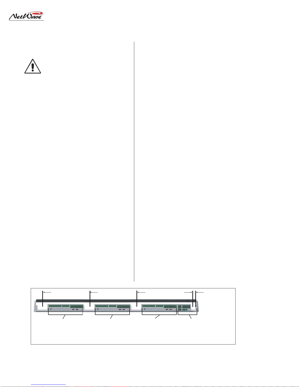
The channel audio and logic wiring connects
sequentiallyalongthebackof the console in eight
channel groups.The chassis metal is cutaway be-
tween the DSP & I/O cards to facilitate getting
the connectors and wiring up through the coun-
tertop.
To ease installation, break out each group of
cables,usingthedimensions shownbelowas mea-
sured from the right end of the cutout. Cabling is
normally broken out and tie wrapped to the bot-
tom of the countertop just behind the cable cut-
out.Leave a six to eight inch service loop on each
cable to ease installation and future wiring
changes.This extra cabling hangs down into the
cabinet (or the cable tray) after being connected.
The monitor and program outputs connect at
the right corner of the console along with the 48-
volt supply, the optional Link cable and the tech-
nical ground wire. The chassis is also cutout in
this area to ease installation.
Plug in all audio and logic cables first. Then
route the excess cabling (i.e., service loops) into
the cabinet by folding the audio and logic wires
over their connectors and arranging the cables to
go into the gap between the connectors and the
flip-up connector cover such that the cover sits
down onto the chassis behind the console display.
The technical ground wire, DC cable and any
Link and LAN cables can now be connected.
POWER SUPPLY PLACEMENT
Two types of power supplies are used with Net-
Wave consoles.Each has a single 48-volt DC out-
put using a keyed and locking connector. Each
uses an IECAC input cable which is shipped with
a USA-type plug.The AC connector, or the IEC
CR AND STUDIO AUDIO & LOGIC OUTPUTS,
PGM BUSES & MIX-MINUS OUTPUTS,
EXT MON INPUTS,
TECHNICAL GROUND POINT,
48VDC SUPPLY INPUT,
LINK CONNECTOR
AUDIO INPUTS & LOGIC I/O
CH 1-8 (NETWAVE-24)
AUDIO INPUTS & LOGIC I/O
CH 9-16 (NETWAVE-24)
CH 1-8 (NETWAVE-16)
AUDIO INPUTS & LOGIC I/O
CH 17-24 (NETWAVE-24)
CH 9-16 (NETWAVE-16)
CH 1-8 (NETWAVE-8)
41" 28" 16" 1" 0"
Console Connections with Access Points (measured from the right end of the cable cutout)
Revision A • 6/06
HARRIS CORPORATION
2-3
2 Installation
cord, will have to be changed for overseas opera-
tion. Both supplies operate from 90 to 240VAC
on 50 or 60 Hz power.
The50-27in-line supplycomesstandard on the
NetWave-8 and NetWave-16 consoles. It has a
captive six-foot DC cable, so it must be located
near the right rear corner of the console. It is typi-
cally set on the wire tray or within the cabinet (it
canbe tiewrappedto averticalwallto savespace).
This supply will get warm under normal use as it
uses free air space for ventilation,so it must never
be covered or enclosed.
The 99-1205 Universal 48-volt Supply comes
standard on the NetWave-24.It requires 2 RU of
rack space within the console cabinetry, typically
located below and to the left or right of the con-
sole.Itis thesamesupply usedwithVistaMaxcard
frames and consoles. A detachable 15-foot DC
cable (90-1858-1) connects this supply to the
NetWave console.
Either supply must be installed such that the
keyed 48-volt supply cable is not under any ten-
sion when routed through the cabinet. The 48-
volt cable locks into a keyed power connector on
the right rear corner of the NetWave chassis.
A 90-1995 Power Coupler (optional) is avail-
able to add a redundant power supply for on-air
consoles.Themain and redundant powersupplies
plug into its specialY-cable,which then plugs into
the console.It hangs below the countertop.
AC GROUNDING NOTE: Do not
defeat the IEC power cord“U”safety
ground in any way, as this may create
a potentially dangerous condition to
the operator.
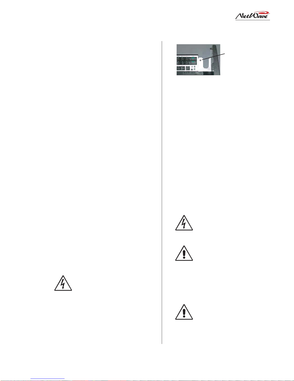
GROUNDING AND SHIELDING
Terminate the facility’s technical ground wire
for the console into a crimped ring tongue termi-
nal suitable for a #8 stud.Fasten the ground wire
totheNetWave chassis usingthe#8 chassis screw
behind the Link connector.
When all system components share a common
groundpotential (byusing isolatedgroundACout-
lets tied individually back to the main technical
ground),theaudio cable shields canbeconnected
at both the console and the peripheral ends.
If isolated ground AC outlets are not used,con-
nect the cable shields at the console end only. Do
not connect the shields on the peripheral device
end. Ensure the peripheral devices connect to a
cleanground throughtheir powercords orthrough
separate ground wires to the facility’s technical
ground.
GROUNDINGNOTE:ThePowerSup-
ply chassis connects to the AC mains
safety or“U”ground wire.
AUDIO GROUND NOISES: Buzz
pickupis generallyelectrostatic—such
as capacitive coupling between an au-
dioline andanACpowerline.To avoid
audio ground noises,do not route au-
dio wires in the same wireway as an
AC power line.
NOTE: Strong electromagnetic fields
from peripheral equipment using
switching power supplies may impair
NetWave performance, so keep these
productsasfar awayas practicalfrom
the console’s location.
Technical Ground Connection Point,
NetWave Chassis,right rear view
Tie a 14-16 AWG
ground wire to this
screw using a ring
tongue fastener

Revision A • 6/06
HARRIS CORPORATION
2-4
2 Installation
COUNTERTOP PREPARATION
Follow the dimensions listed on page 2-1 to
markandrouter thecableaccess opening through
the countertop and substrate. Always radius the
corners to prevent laminate cracks.
NOTE: If the console will be set against a wall,
leave a .5" [13] gap between the side panels and
the wall in order to flip-up the connector cover.
Center the console over the cable access cutout
sothatthe rear connectorcover,whenclosed,cov-
ers the cutout.
For security or stability the console can be fas-
tened to the countertop. To do this, the leftmost
Dual Fader panel and the Monitor Panel must be
removed to access the two chassis holes (see page
2-1 for hole locations).
Removing Control Panels
Control panels are fastened to the frame using
3mm silver hex screws. The panels connect to
frame cards using short red CAT-5 cables.
To remove a control panel:
1. Remove the 3mm hex screws that fasten the
panel to the frame (a hex driver is in the op-
tional76-1901 NetWave/SMXdigitaltoolkit).
2. Movethat panel’sfaderstofull off andusethe
two fader knobs to lift up the panel enough to
remove the panel by its metal extrusion.
WARNING: The red CAT-5 cable connecting
the panel is short, so lift the panel up just
enough to clear the console surface.
3. Unplug the CAT-5 cable from the panel.If the
panel is a Dual Router panel, there will be a
two labeled CAT-5 cables.
Before marking the holes to fasten the console
tothecountertop,makesure the consoleisset par-
allel to the countertop edge and is covering the
cablecutout.Mark,then movethe console,todrill
pilot holes for screws or clear holes for bolts. On
laminate countertops it is important that the hole
through the laminate is larger than the screw or
bolt threads to prevent future laminate cracks.
Use #8 or #10 screws or bolts to fasten the con-
sole to the countertop substrate. Do not deform
the chassis, or unbalance the rubber feet, by ap-
plying excessive torque on the screws or bolts.
NOTE: Install the optional Link Acti-
vation kit at this time while the Moni-
tor panel is already out of the chassis.
Theinstallinstructions areonthe next
page. Also, if changes are needed on
the Monitor & Output card setup
switches, they should be done at this
time as well. Switch setting informa-
tion is on page 2-10.
Reinstall the panels into the frame, using the
reverseorderto theirremoval.The redCAT-5cable
plugs into J5 on the Dual Fader panels.
INSTALLING CONSOLE OPTIONS
AllNetWaveconsoles ship fromthefactory in a
standardconfiguration.Anyconsoleoptions(Link
Activationkit,DualRouter kit,QuadMeter pack-
age, additional Dual Fader panels) will be sepa-
rately packaged and must be installed into the
console. Optional items can be installed during
console installation or at any future time.
Installing the Link Activation kit or a Quad
Meter package requires that the console be
unpowered during the installation.The other kits
can be installed while the console is powered.
LinkActivationKit
The LinkActivationkitturnsanyNetWavefrom
a non-networked, stand-alone console into a net-
worked or Linked console that is ready to con-
nect into aVistaMax audio management system.
Table of contents
Other Harris Music Mixer manuals


Popular Music Mixer manuals by other brands


PROART
PROART A 5430 Installation & operating instructions

Peavey
Peavey XRD 680S operating guide

High End Systems
High End Systems ROAD HOG Quick start guides

Behringer
Behringer B-Control Deejay BCD3000 Technical specifications

Roland
Roland Groovebox MC-707 Reference manual

YORKVILLE
YORKVILLE YS1080 Service manual


