Omron F39-MC11 User manual

PNSPO!
Model F39-MC11(ver. 3)
Setting Console
INSTRUCTION MANUAL
Thank you for selecting OMRON product. This manual primarily
describes precautions required in installing and operating the product.
Before operating the product, read this manual thoroughly to acquire
sufficient knowledge of the product. For your convenience, always keep
this manual at hand.
©OMRON Corporation 2001-2003 All Rights Reserved.
i
Read and Understand this Instruction Manual
Please read and understand this instruction manual before storing,
installing, programming, operating, maintaining, or disposing of the
products. Please consult your OMRON representative if you have any
questions or comments.
Warranty, Limitations of Liability
WARRANTY
OMRON's exclusive warranty is that the products are free from
defects in materials and workmanship for a period of one year (or
other period if specified) from date of sale by OMRON.
OMRON MAKES NO WARRANTY OR REPRESENTATION,
EXPRESS OR IMPLIED, REGARDING NON-INFRINGEMENT,
MERCHANTABILITY, OR FITNESS FOR PARTICULAR PURPOSE
OF THE PRODUCTS. ANY BUYER OR USER ACKNOWLEDGES
THAT THE BUYER OR USER ALONE HAS DETERMINED THAT
THE PRODUCTS WILL SUITABLY MEET THE REQUIREMENTS OF
THEIR INTENDED USE. OMRON DISCLAIMS ALL OTHER
WARRANTIES, EXPRESS OR IMPLIED.
LIMITATIONS OF LIABILITY
OMRON SHALL NOT BE RESPONSIBLE FOR SPECIAL,
INDIRECT, OR CONSEQUENTIAL DAMAGES, LOSS OF PROFITS
OR COMMERCIAL LOSS IN ANY WAY CONNECTED WITH THE
PRODUCTS, WHETHER SUCH CLAIM IS BASED ON CONTRACT,
WARRANTY, NEGLIGENCE, OR STRICT LIABILITY.
In no event shall the responsibility of OMRON for any act exceed the
individual price of the product on which liability is asserted.
IN NO EVENT SHALL OMRON BE RESPONSIBLE FOR
WARRANTY, REPAIR, OR OTHER CLAIMS REGARDING THE
PRODUCTS UNLESS OMRON'S ANALYSIS CONFIRMS THAT THE
PRODUCTS WERE PROPERLY HANDLED, STORED, INSTALLED,
AND MAINTAINED AND NOT SUBJECT TO CONTAMINATION,
ABUSE, MISUSE, OR INAPPROPRIATE MODIFICATION OR
REPAIR.

- ii -
Application Considerations
SUITABILITY FOR USE
OMRON shall not be responsible for conformity with any standards,
codes, or regulations that apply to the combination of the products in
the customer's application or use of the products.
At the customer's request, OMRON will provide applicable third party
certification documents identifying ratings and limitations of use that
apply to the products. This information by itself is not sufficient for a
complete determination of the suitability of the products in
combination with the end product, machine, system, or other
application or use.
The following are some examples of applications for which particular
attention must be given. This is not intended to be an exhaustive list
of all possible uses of the products, nor is it intended to imply that the
uses listed may be suitable for the products:
• Outdoor use, uses involving potential chemical contamination or
electrical interference, or conditions or uses not described in this
instruction manual.
• Nuclear energy control systems, combustion systems, railroad
systems, aviation systems, medical equipment, amusement
machines, vehicles, and installations subject to separate
industry or government regulations.
Systems, machines, and equipment that could present a risk to
life or property.
Please know and observe all prohibitions of use applicable to the
products.
NEVER USE THE PRODUCTS FOR AN APPLICATION INVOLVING
SERIOUS RISK TO LIFE OR PROPERTY WITHOUT ENSURING
THAT THE SYSTEM AS A WHOLE HAS BEEN DESIGNED TO
ADDRESS THE RISKS, AND THAT THE OMRON PRODUCTS ARE
PROPERLY RATED AND INSTALLED FOR THE INTENDED USE
WITHIN THE OVERALL EQUIPMENT OR SYSTEM.
PROGRAMMABLE PRODUCTS
OMRON shall not be responsible for the user's programming of a
programmable product, or any consequence thereof.
- iii -
Disclaimers
CHANGE IN SPECIFICATIONS
Product specifications and accessories may be changed at any time
based on improvements and other reasons.
It is our practice to change model numbers when published ratings or
features are changed, or when significant construction changes are
made. However, some specifications of the products may be
changed without any notice. When in doubt, special model numbers
may be assigned to fix or establish key specifications for your
application on your request. Please consult with your OMRON
representative at any time to confirm actual specifications of
purchased products.
DIMENSIONS AND WEIGHTS
Dimensions and weights are nominal and are not to be used for
manufacturing purposes, even when tolerances are shown.
ERRORS AND OMISSIONS
The information in this instruction manual has been carefully checked
and is believed to be accurate; however, no responsibility is assumed
for clerical, typographical, or proofreading errors, or omissions.
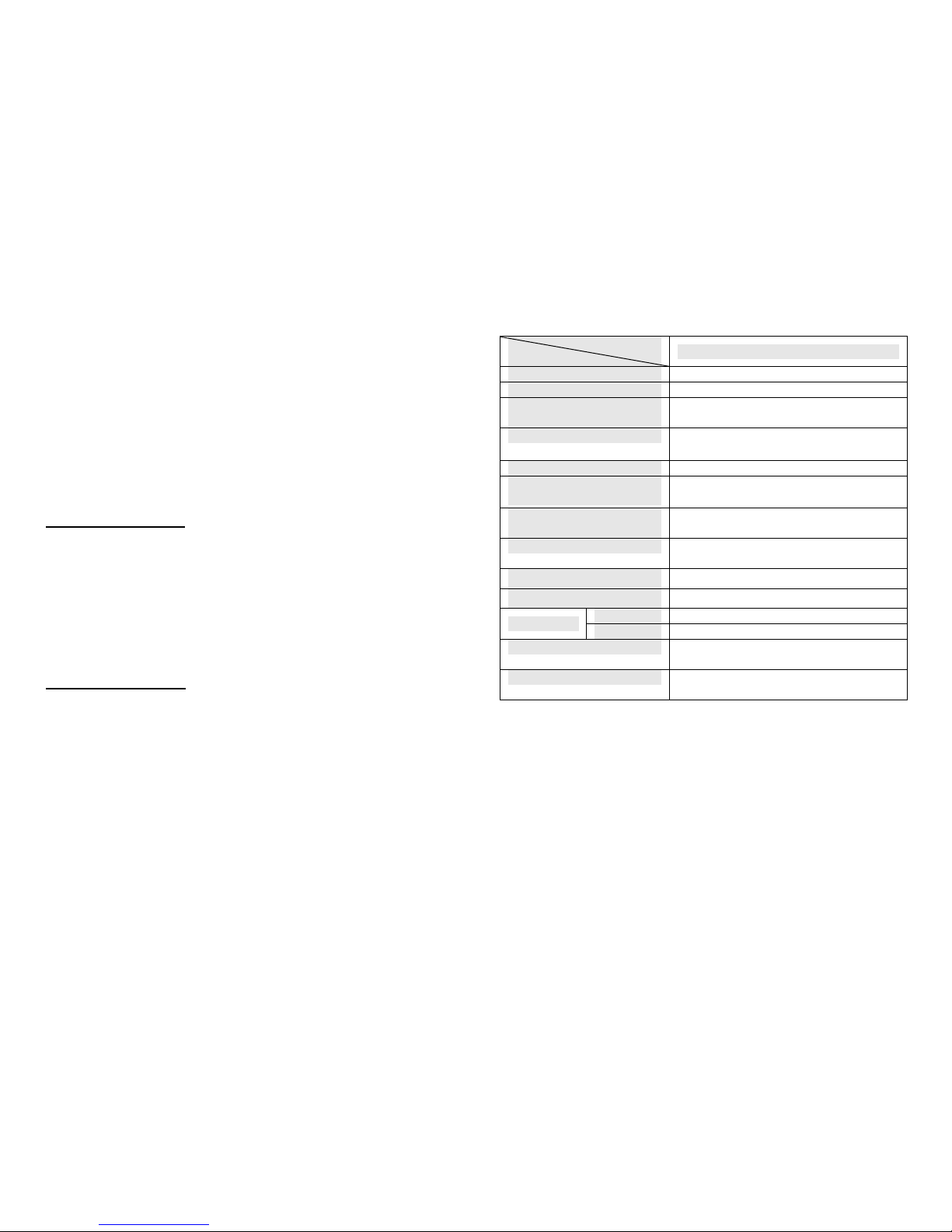
Meanings of Signal Words
The following signal words are used in this instruction manual.
WARNING
Indicates a potentially hazardous situation which,
if not avoided, will result in minor or moderate
injury, or may result in serious injury or death.
Additionally there may be significant property
damage.
CAUTION
Indicates a potentially hazardous situation which,
if not avoided, may result in minor or moderate
injury or in property damage.

- iv -
Meanings of Alert Symbols
The following alert symbols are used in this instruction manual.
Indicates the possibility of explosion under specific
conditions.
Alert statements in this Instruction Manual
The following alert statements apply to the products in this instruction
manual. Each alert statement also appears at the locations needed in
the manual to attract your attention.
WARNIG
F39-MC must be managed and used only by qualified persons.
Operation by un-qualified persons could create a hazardous condition
which may lead to a loss of safety function.
After the changing the setting of the sensor, a start-up check must
be conducted. Normal operation can only be allowed after safety
is confirmed.
In order prevent access to a dangerous area, fixed barrier guards must
be placed in fixed blanked areas.
Failure to do so may result in serious injury.
Use of floating blanking function involves a change of the safety distance.
Always recalculate and re-measure the safety distance to confirm that it
meets the applicable standards, after the change.
Failure to do so may cause the machine to fail to stop before an operator
reaches a dangerous area, and may result in serious injury.
A change of the setting can only be done under observance of laws/
standards which are related to safe operation of the product.
CAUTION
Do not connect the F39-MC to any equipment other than for
what it intended to be used with.
- v -
Precautions for Safe Use
Please observe the following precautions for safe use of the products.
• Do not connect to voltage exceeding the stated values. Doing so
may cause damage to the product.
• Do not expose the F39-MC to water on the product. Doing so
may cause damage to the product.
Precautions for Correct Use
Please observe the following precautions to prevent failure to operate,
malfunctions, or undesirable effects on product performance.
• Always power OFF the sensor when connecting or
disconnecting the F39-MC11.
• When F39-MC is not in use, disconnect it from the sensor.

- vi -
Table of Contents
1DESCRIPTION .............................................................................. 1
1.1 Outline of operation procedure.................................................2
1.2 Available function and Sensor serial number ...........................3
2RATING ......................................................................................... 4
3NOMENCLATURE......................................................................... 5
4WIRING/CONNECTION ................................................................ 7
4.1 Mounting branching connector ................................................. 7
4.2 Diagram for Wiring of Branching Connector.............................8
4.3 Connecting F39-MC .................................................................9
5POWER ON................................................................................. 10
6FUNCTION SELECTION..............................................................11
7CHANNEL SELECTION .............................................................. 12
8MONITOR/SET............................................................................ 14
8.1 Fixed blanking ........................................................................16
8.2 Floating blanking ....................................................................21
8.3 Auxiliary output ....................................................................... 24
8.4 Output2................................................................................... 24
8.5 External indicator output.........................................................27
8.6 External device monitoring ..................................................... 30
8.7 Start interlock..........................................................................31
8.8 Restart interlock......................................................................32
8.9 Threshold adjustment.............................................................33
8.10 Setting initialization.................................................................34
8.11 ID setting ................................................................................35
8.12 Threshold teach......................................................................36
8.13 Error log view..........................................................................40
9COPY .......................................................................................... 41
9.1 Upload (Copy Sensor data to F39-MC) .................................. 42
9.2 Download (Copy F39-MC data to Sensor) .............................43
9.3 Bank Lock (Prohibit overwriting to bank data)........................44
10 PROTECT ............................................................................. 45
10.1 Setting lock.............................................................................46
10.2 Change password...................................................................47
10.3 Setting limitation .....................................................................48
11 DISCONNECT F39-MC......................................................... 50
12 MC11 ERROR CODES ......................................................... 51
13 TROUBLESHOOTING .......................................................... 52
ANNEX1 INDEX .................................................................................. 53
ANNEX2 FUNCTION LIST (according to sensor type) ....................... 56
ANNEX3 ERROR CODE LIST ............................................................ 60
ANNEX4 FUNCTION SETTING CARD ............................................... 61
0

- 1 -
1 DESCRIPTION
The Setting consol Model F39-MC11 (hereafter referred to as F39-MC)
can be connected to Safety Light Curtain Series—Model F3SN,
Multi-beam Safety Sensor series—Model F3SH, and Area Scanner
series—Model F3ZN. The F39-MC allows you to change or monitor the
setting of these sensors.
Available setting functions are as follows;
Function Setting F3SN F3SH F3ZN
Fixed blanking
Floating blanking
Auxiliary output
Output2
External indicator output
External device monitoring
Start interlock
Restart interlock
Threshold adjustment
Setting initialization
ID setting
Threshold teach *
Monitor/
Set
Error log view
Copy Upload
Download
Bank lock
Protect Setting lock
Change password
Setting limitation
: Accessible
* For the sensor having the specific serial number, this function is
unavailable.
Refer to “ 1.2 Available function and Sensor serial number ”.
- 2 -
1.1 Outline of operation procedure
Shown in the following flow chart.
⑨Power on sensor(s) and
confirm correct function
by the test.
Outline of operation
procedure
Setting completed.
(Able to normal use)
See section 6
See section 7
See section 4.1
See section 4.3
See section 5
①Mount branching connector
②Connect cable and F39-MC
③Power on both sensor(s)
and F39-MC
④Select function
(MONITOR/SET, COPY,
PROTECT)
⑤Select channel of sensor
to be set
⑥Select sensor function to
be set, and change value
⑦Send changed setting to
sensor(s)
⑧Power OFF, and detach
F39-MC and cable
See section 8 to 10
See section 11
See section 8 to 10

- 3 -
1.2 Available function and Sensor serial number
For the sensor having the specific serial number, there are some
unavailable functions in the functions of the F39-MC11.
Check the serial number on the type label of the sensor for both emitter
and receiver to make sure available functions for the sensor.
New functions are divided into two function groups, the functional group
A and the functional group B, by the serial number of the sensor.
Refer to “ANNEX2 FUNCTION LIST (according to sensor type)”(Page
56) about functions corresponding to each group.
The method to distinguish between the functional group A and the
functional group B is as follows.
The functional group A
The following serial numbers correspond to the functional group A.
Serial number:
aaaa402, aaaa502, aaaa602, aaaa702, aaaa802, aaaa902,
aaaaX02, aaaaY02, aaaaZ02, or aaaabcc
'aaaa' can be any numeric characters.
'b' can be any alphanumeric characters.
'cc' is greater than '03'
The functional group B
The following serial numbers correspond to the functional group B.
Serial number:
0001803~, aaaa903, aaaaX03, aaaaY03, aaaaX03, or aaaabcc
'aaaa' can be any numeric characters.
'b' can be any alphanumeric characters.
'cc' is greater than '04'.
- 4 -
2 RATING
Models
Items F39-MC11
Applicable sensor F3SN, F3SH, F3ZN Series
Communication method Specified method
Communication
connecting method RS-485
Power supply 24VDC±10%
(share sensor’s power supply)
Current consumption 55mA maximum
Ambient temperature
(during operation)
-10℃to 55℃
(with no freezing)
Ambient temperature
(during storage)
-25℃to 65℃
Ambient humidity 25 to 85%RH
(with no condensation)
Insulation resistance 20MΩmin.(at 500VDC)
Dielectric strength voltage 1,000VAC at 50/60Hz for 1min.
Case ABS
Material Window Polycarbonate
Weight Approx. 87g (without accessories)
Approx. 360g (when packed)
Accessories Branching connector, Cable(2m),
Connector cap, Instruction manual

- 5 -
3 NOMENCLATURE
Cable (Length: 2m)
+
|
CONNECT
PNSPO
+
-
MONITOR / SET
COPY
PROTECT
MENU
Setting Console
F39-MC11
CANCEL ENTER
Communication
connection indicator
(CONNECT)
DOWN
UP
RL
Function indicators
(FUNCTION)
Channel display
(CH)
Channel keys(CH)
Mode display
Operation keys
UP Change mode, increase value
DOWN Change mode, decrease value
RIGHT digit position down
LEFT digit position up
CANCEL To cancel
ENTER To set
Branching
Connector
Sensor
(F3SN, F3SH, or
F3ZN series)
MADE IN JAPAN
FUNCTION
CH
Connector Cap
Please set this to branching
connector when F39-MC is
not in use.
Brief description of Operation keys
- 6 -
+
-
CANCEL ENTER
DOWN
RL
UP
MONITOR / SET
COPY
PROTECT
FUNCTION
3.1 Communication connection indicator (CONNECT)
This indicator will light up when F39-MC is
connected to the sensor.
F39-MC cannot be used when this indicator is not lit.
3.2 Function indicators (FUNCTION)
The indicator of the function being set is lit.
3.3 Channel display(CH) and channel keys
Using +/- keys, select sensor to be set by
F39-MC.
Number of selected channel appears on
display.
3.4 Mode display
Displays function and value when making a
setting.
Basically the top row indicates Setting
function and the bottom row Setting value.
3.5 Operation keys
Used for mode change, setting and
canceling.
+
|
CH
CONNECT

- 7 -
4 WIRING/CONNECTION
4.1 Mounting branching connector
Mount a branching connector to sensor. The connector can be
mounted either on emitter or receiver.
When mounted on receiver When mounted on emitter
Branching
connector
Emitter Receiver Emitter Receiver
- 8 -
4.2 Diagram for Wiring of Branching Connector
Front View Pin
No. Signal
1 +24 V(24VDC)
2 RS-485(A)
3 0V
4 RS-485(B)
CAUTION
The F39-MC receives its power from the sensor. Select a power supply
with sufficient current to allow for the additional consumption of the
F39-MC (55mA maximum).
①8Pin female
To sensor
②8Pin male
To p o w e r
supply circuit
③4Pin female
To F 3 9 -M C
2
4
31

- 9 -
4.3 Connecting F39-MC
Insert M12 connector of the cable into Branching connector and the
other end into the F39-MC11.
CAUTION
Do not connect 2 or more F39-MC to one pair of sensor. Normal
operation cannot be achieved. Also, combined use of F39-MC and
F3ZP, area scanner controller, is not allowed.
When F39-MC is not in use, the cable and F39-MC must be removed
and Branching connector must be covered with connector cap (Model
XS2Z-12).
When connecting or disconnecting the F39-MC, be sure that the power
is OFF.
- 10 -
5 POWER ON
Power supply of F39-MC is shared with that of the sensor.
The F39-MC turns ON with the power supply of the sensor.
When the F39-MC power is ON, it confirms its
connection to sensor. When connection is succeeded,
it displays as follows;
・Communication connecting indicator is lit.
・Displays F39-MC’s model and version in mode
display (for 1 second)
・Displays connected sensor model in mode display,
(for 1 second)
(Figure shown left represents when connected to
Model F3SN-A.)
CAUTION
When F39-MC power is ON, the state of sensor
becomes as follows.
• The safety output of F3SN and F3SH is OFF.
Also, indicators located at bottom (see fig. on
right) are flashing.
• The output of F3ZN is OFF only during
sending data to F3ZN. During non-access
time, normal operation can be conducted
except that the response time increases by
1ms.
Do not disconnect the F39-MC during power
ON-state. Malfunction may result.

- 11 -
6 FUNCTION SELECTION
1. Using [UP][DOWN] keys, select the function. Display of selected
function flashes.
2. Function selecting method is shown below.
3. By pressing [ENTER] when the selected function is displayed,
editing of selected function becomes possible. The indicator of the
function selected will light.
4. For editing method of each function, please refer to the item of
respective function.
・ Monitor/Set Section8 page14
・ Copy Section9 page41
・ Protect Section10 page45
-
DOWN
+
UP
MONITOR / SET
COPY
PROTECT
FUNCTION
MONITOR / SET
COPY
PROTECT
FUNCTION
MONITOR / SET
COPY
PROTECT
FUNCTION
-
DOWN
+
UP
- 12 -
7 CHANNEL SELECTION
When changing the setting of the sensor with the F39-MC, select the
channel in order to determine which sensor is to be set.
Selecting channel (CH) method is as follows;
When series connected, the closest sensor to the extension cable
becomes 1CH and the second closest becomes 2CH.
Channel Numbers in Series Connection
3CH
2CH
1CH

- 13 -
Changing selected channel
when connected to three sensors
+
|
CH(+)CH(-)
+
|
CH(+)CH(-)
+
|
CH(+)CH(-)
1ch is selected
(After power on)
2ch is selected
3ch is selected
1ch is selected
The indicator will be displayed as illustrated below, depending on which
function is to be set. This indicates that a setting item is to be
proceeded to all the sensors.
CAUTION
If the channel is changed while making a setting, content of the setting
will be cancelled.
- 14 -
8 MONITOR/SET
CAUTION
After the changing the setting of the sensor, a start-up check must
be conducted. Normal operation can only be allowed after safety is
confirmed.
A change of the setting can only be done under observance of laws/
standards which are related to safe operation of the product.
This function enables the monitoring of current set values and functions
of the sensor. When a set value is changed, content of the change is
reflected on sensor. The value which is indicated first in each category
is the current set value.
The method of change into each mode is as illustrated below.
By pressing [ENTER] key when the selected function is displayed,
editing of selected function becomes possible.
(i)F3SN
1.Fixed blanking 2.Floating blanking 4.Ext. indicator output
3.Auxiliary output
5.Ext. device monitor
9.initialize
0.ID 7.Restart interlock
6.Start interlock
1.FIX 2.FLO 3.AUX 4.E.I.O.
5.EDM
6.SIL
7.RIL9.INI0.ID
[UP][DOWN]Key
Blinking
A.Threshold teach
A.TCH
B.Error log view
B.LOG

- 15 -
(ii)F3SH
3.Auxiliary output
9.Initialize
0.ID
7.Restart interlock
6.Start interlock
3.AUX 4.E.I.O.
4.Ext. indicator output 5.Ext. device monitor
5.EDM 6.SIL
7.RIL
9.INI0.ID
A.Threshold teach
A.TCH
B.Error log view
B.LOG
(iii)F3ZN
1.Fixed blanking 3.Output #2
8.Threshold
2.Floating blanking 4.Ext. indicator output
9.Initialized
0.ID
9.INI0.ID
1.FIX 2.FLO 3.OU2 4.E.I.O.
8.TH
B.Error log view
0.LOG
<Common Note for MONITOR/SET function>
1. Edited value will not become active if NOT “SEND” to sensor, nor
“Function Valid (1.Fun-on)” is not selected.
2. “Loc” may display if “Setting lock” or “Setting limitation” has been
set. See clause10.1 and 10.3.
3. Please do not drop a power supply on the "Send" display after
pushing the [ENTER] key before being displayed as "Good." When
a power supply should be dropped, a sensor may not carry out
normal operation.
- 16 -
8.1 Fixed blanking
<F3SN, F3ZN>
CAUTION
In order prevent access to a dangerous area, fixed barrier guards
must be placed in fixed blanked areas.
Failure to do so may result in serious injury.
When Floating blanking function is enabled simultaneously, the
beam more than a plan may become invalid.
Please perform sufficient verification, when you confirm both
functions simultaneously.
Failure to do so may result in serious injury.
Fixed blanking function partly voids detection zone of sensor. Entrance
of object into invalid detection zone does not change output status.
There are two ways to choose which zone is to be blanked.
1. Teaching: Blocked beams are set as beams for blanking. Error will
be displayed if there are no blocked beams.
2. Manual: Select beam number first, and then choose
blanked/not blanked for each selected beam. Beams are
numbered as below figure.
7
6
5
4
3
2
1

- 17 -
<Surveillance mode>
F3SN can set up the following operation in consideration of safety.
1. Setting release at the light receiving condition
In case a blanked beam becomes clear, F3SN will automatically
invalids fixed blanking function. In other words, no blanked beam
will exist. Reset of power makes previous fixed blanking setting
active.
2. Lockout mode at the light receiving condition
In case a blanked beam becomes clear, F3SN will become lockout
condition. Reset of power, or Reset input makes previous fixed
blanking setting active.
Make sure to make blanked areas so that no one can reach to the
dangerous part from blanked areas. All blanked beams need to be
blocked by object.
The above functions are only implemented on F3SN, where safety is
necessary. For F3ZN, fixed blanking function continues even if blanked
beam becomes clear.
<Note>
Models produced before April 2002 can not use setting of "Surveillance
mode". Sensors which has specific serial number also can not use the
setting. (If the surveillance mode is set to above model, "setting release
at the light receiving" is always set.) Please confirm at the time of a
setup.
- 18 -
<F3SN>
Go to ②-2
001:Select beam num.
①
z
②-1 ②-2 ②-3 ②-4
Go to ①
after 1 sec.
Go to ②-4
after 1 sec
Fixed blanking
Error
Function Valid
Beam select (manual)
Setting completed
Function Valid Beam select (Teach)
Beam select (Teach)
Send to sensor
ON:Valid
OFF:Invalid
ON:Beam selected
OFF:Beam un-selected
ENT:Beam(s) selected
Go to ②-3
after 1 sec
CLR:Clear selected
beam(s)
When "teached", blocked
beams are selected.
Note: When "Enter" key
pressed with no blocked
beams, "Err" is displayed.
OR
OR
Blinking [Cancel] Key
[Enter] Key
[Up][Down] Key
1.FIX
②-1-1
1.FUN 2.TCH
②-2-1
3.MAN
②-3-1 ②-4-1
SEND
②-2-2
GOOD
ERR
②-3-2
GOOD
ERR
②-3-3
GOOD
ERR
②-5
Surveillance mode
Go to ②-5
Surveillance mode
Lockout mode at the
light receiving condition
Setting release at the
light receiving condition
3.MON

- 19 -
<F3SN, F3ZN>
About F3SN, it becomes the following displays by the serial number.
Go to ②-2
001:Select beam num.
①
z
②-1 ②-2 ②-3 ②-4
Go to ①
after 1 sec.
Go to ②-4
after 1 sec
Fixed blanking
Error
Function Valid
Beam select (manual)
Setting completed
Function Valid Beam select (Teach)
Beam select (Teach)
Send to sensor
ON:Valid
OFF:Invalid
ON:Beam selected
OFF:Beam un-selected
ENT:Beam(s) selected
Go to ②-3
after 1 sec
CLR:Clear selected
beam(s)
When "teached", blocked
beams are selected.
Note: When "Enter" key
pressed with no blocked
beams, "Err" is displayed.
OR
OR
Blinking [Cancel] Key
[Enter] Key
[Up][Down] Key
1.FIX
②-1-1
1.FUN 2.TCH
②-2-1
3.MAN
②-3-1 ②-4-1
SEND
②-2-2
GOOD
ERR
②-3-2
GOOD
ERR
②-3-3
GOOD
ERR
- 20 -
Example of how to set fixed blanking.
Example1:Set Fixed Blanking using "teaching"
②-1-1:Select "1.Fun-on"(Function valid)
Place an object where you want to be "blanked"
②-2-1:Select "2.tch-Ent"(Beams select)
②-4:Send setting to sensor
Setting completed
[good] displayed
ONE POINT:
After setting has completed, you can confirm the
blanked beam numbers by using ②-3:Manual Beam
select menu.
[good] displayed
[Err] displayed・・・Object is not mounted properly.
Replace it and try ②-2 again.
[Err] displayed・・・Couldn't send setting to sensor.
Check wiring, etc. and try again from the beginning
Example2:Set Fixed Blanking using "manual"
②-1-1:Select "1.Fun-on"(Function valid)
②-3:Select "3.man"(manual beam select)
②-3-1:Input beam number to be "blanked"
②-3-2:Select "on"(beam selected)
②-4:Send setting to sensor
Setting completed
[good] displayed
[good] displayed
In order to "blank" more than one beam, repeat
Select beam number -> select "on" -> [CANCEL] Key
command, and push [ENTER] key at the end.
[Err] displayed・・・Couldn't send setting to sensor.
Check wiring, etc. and try again from the beginning
[Err] displayed・・・Wrong beam number was inputted.
Input correct number and try again.

- 21 -
8.2 Floating blanking
<F3SN, F3ZN>
CAUTION
Use of floating blanking function involves a change of the safety
distance. Always recalculate and re-measure the safety distance to
confirm that it meets the applicable standards, after the change.
Failure to do so may cause the machine to fail to stop before an operator
reaches a dangerous area, and may result in serious injury.
When Fixed blanking function is enabled simultaneously with floating
blanking function, more beams than your plan may become invalid.
Perform sufficient verification, when you use both functions
simultaneously.
Failure to do so may result in serious injury.
Floating blanking function allows the output to remain ON when beams
of the sensor are interrupted anywhere in the field. In contrast with fixed
blanking function, which invalids fixed detection area, floating blanking
function ignores object smaller than specified radius.
Floating can be set for 1 to 3 floating beams.
(When 1 floating beam is set, sensor will turn OFF when 2 or more
beams are blocked).
- 22 -
CAUTION
Use of floating blanking function involves a change of the safety
distance. Always recalculate and re-measure the safety distance to
confirm that it meets the applicable standards, after the change.
Failure to do so may cause the machine to fail to stop before an operator
reaches a dangerous area, and may result in serious injury.
Resolution
(mm)
Undetectable
dia.(mm)
Floating beam
Beam gap(mm) 0 1 2 3 1 2 3
9 14 23 32 41 4 13 22
15 25 40 55 70 5 20 35
30 40 70 100 130 20 50 80
60 70 130 190 250 50 110 170
The following modes can be set in floating blanking function;
1. Sequential beam mode
- ON: Output becomes OFF when consecutive blocked beams
exceeds floating beams. Output will not becomes OFF
when plural objects smaller than undetectable diameter
exist.
- OFF: Output becomes OFF when sum of blocked beams exceeds
floating beams. Output may becomes OFF when plural
objects smaller than undetectable diameter exist.
2. Outermost beam invalid mode
Outermost beam invalid mode excludes outermost beams from
floating blanking.
When this mode is valid, the output will turn OFF if one of the
outermost beams is blocked, even if floating blanking is active.

- 23 -
①
②-1 ②-2 ②-3 ②-4 ②-5
Go to ②-3
Go to ②-4 Go to ②-5
Floating blanking
Sequential modeFunction Valid Floating beam no. Outermost beam invalid
Function valid Floating beam no. Sequential mode Outermost beam invalid Send to sensor
Setting completed
Error
Blinking [Cancel] Key
[Enter] Key
[Up][Down] Key
1:1 floating beam
Go to ①
after 1 sec.
2:2 floating beams
3:3 floating beams
CLR: floating beams
clear
2.FLO
1.FUN
②-1-1
2. NO. 3.SEQ 4.O.B.I. SEND
②-2-1 ②-3-1 ②-4-1 ②-5-1
Go to ②-2
ON:Valid
OFF:Invalid
ON:Valid
OFF:Invalid
ON:Valid
OFF:Invalid
GOOD
ERR
- 24 -
8.3 Auxiliary output
<F3SN, F3SH>
This is a non-safety related output used to display a status.
This output cannot be used for the purpose of safety.
This can be selected to the following output;
1. DarkON
2. Light ON
3. Light diagnosis
4. Lockout
5. Outermost beam monitoring
6. Blanking monitoring
7. Specified beam
For detail of each output, please refer to ANNEX1 INDEX.
<Note>
Because F3SH does not have fixed blanking function, “6. Blanking
monitoring” is not selectable.
8.4 Output2
<F3ZN>
This is a output of F3ZN used to display a status.
Available signals are the same as 8.3 Auxiliary output.

- 25 -
③-2
①
Auxiliary output
Setting completed
Error
Send to sensor
②-7
Specified beam
②-6
Blanking monitor
②-5
Outermost beam monitor
②-4
Lockout
②-3
Light diagnosis
②-2
Light ON
②-1
Dark ON
Beam select (Teach)
③-1(from ②-7)
OR
ENT:Beam(s) selected
CLR:Clear selected
beam(s)
Go to ③-2
after 1 sec.
(Only when ②-7 is
selected, go to ③-1)
Blinking [Cancel] Key
[Enter] Key
[Up][Down] Key
Go to ①
after 1 sec.
When "teached", blocked
beams are selected.
Note: When "Enter" key
pressed with no blocked
beams, "Err" is displayed.
3.AUX
1.D.ON 2.L.ON 3.L.DG 4.L.OU
5.O.B.M.6.BLN7.SPC
③-1-1
GOOD
ERR
SEND
③-2-1
GOOD
ERR
- 26 -
③-2
①
Setting completed
Error
Send to sensor
②-7
Specified beam
②-6
Blanking monitor
②-5
Outermost beam monitor
②-4
Lockout
②-3
Light diagnosis
②-2
Light ON
②-1
Dark ON
Beam select (Teach)
③-1(from ②-7)
OR
ENT:Beam(s) selected
CLR:Clear selected
beam(s)
Go to ③-2
after 1 sec.
(Only when ②-7 is
selected, go to ③-1)
Blinking [Cancel] Key
[Enter] Key
[Up][Down] Key
Go to ①
after 1 sec.
When "teached", blocked
beams are selected.
Note: When "Enter" key
pressed with no blocked
beams, "Err" is displayed.
1.D.ON 2.L.ON 3.L.DG 4.L.OU
5.O.B.M.6.BLN7.SPC
③-1-1
GOOD
ERR
SEND
③-2-1
GOOD
ERR
Output #2
3.OU2

- 27 -
8.5 External indicator output
<F3SN, F3SH F3ZN>
This is a non-safety related output which can be connected to an
optional indicator, such as F39-A01P-.
Applicable only to the models which can be connected in series.
This can be selected to the following output;
1. DarkON
2. Light ON
3. Light diagnosis
4. Lockout
5. Test input-ON
6. Test input-OFF
7. Blanking setting
For detail of each output, please refer to ANNEX1 INDEX.
<Lighting pattern setup>
Display Lighting pattern setup
LIHt Light
bln.1 It blinks in a cycle of 0.5 seconds.
bln.2 It blinks in a cycle of 1 seconds.
bln.3 It blinks in a cycle of 2 seconds.
<Note>
1. F3ZN can set up only 1-4.
2. There are some which cannot set up above 5-7 by the serial
number about F3SN and F3SH.
3. There are some which cannot set up a blink pattern by the serial
number. (Light only)
4. Because F3SH does not have fixed blanking function, “7.
Blanking setting” is not selectable.
- 28 -
<F3SN, F3SH>
⑤-1
①
Setting completed Error
Send to sensor
②-4
Lockout
②-3
Light diagnosis
②-2
Light ON
②-1
Dark ON
Blinking [Cancel] Key
[Enter] Key
[Up][Down] Key
Go to ①
after 1 sec.
1.D.ON 2.L.ON 3.L.DG 4.L.OU
SEND
⑤-2
GOOD ERR
Ext. indicator output
4.E.I.O.
②-6 ②-5
Test input-ON
Test input-OFF
7.b.L.S 6.t.OF 5.t.on
④-1
Lighting pattern setup
LIHt bLn.1
bLn.2 bLn.3
②-7
Blanking setting
③
Lighting pattern setup
FLSH

- 29 -
<F3SN, F3SH, F3ZN>
About F3SN and F3SH, it becomes the following displays by the serial
number.
③-1
①
Setting completed Error
Send to sensor
②-4
Lockout
②-3
Light diagnosis
②-2
Light ON
②-1
Dark ON
Blinking [Cancel] Key
[Enter] Key
[Up][Down] Key
Go to ①
after 1 sec.
1.D.ON 2.L.ON 3.L.DG 4.L.OU
SEND
③-2
GOOD ERR
Ext. indicator output
4.E.I.O.
- 30 -
8.6 External device monitoring
<F3SN, F3SH>
This function can detect malfunction of external device which controls
hazardous area of machine. (e.g. contact welding)
The determination time can be set in respect to the response time of
relay being used. The setting time must be between 100ms to 600ms
and can be set in 5ms increments.
①
②-1
Go to ②-2
Change delay time
using [UP][DOWN]
[L][R]keys.
(100 to 600 ms;
every 5ms)
②-2
Go to ②-3
②-3
Ext. device monitor
Function valid Acceptable delay time Send to sensor
Function valid
Error
Setting completedSelect time (ms)
Blinking [Cancel] Key
[Enter] Key
[Up][Down] Key
Go to ①
after 1 sec.
5.EDM
②-1-1 ②-2-1 ②-3-1
1.FUN 2.TIM SEND
ON:Valid
OFF:Invalid
300 GOOD
ERR

- 31 -
8.7 Start interlock
<F3SN, F3SH>
When this function is ON, the outputs remain in the OFF-state (i.e.
interlock state) after power ON. Interlock state can be released by a
manual reset when there are no obstructions in the detection zone.
CAUTION
This function is valid only when using manual reset mode. When in
auto reset mode, the start interlock function is automatically
disabled.
②-1 ②-2
Start interlock
Setting completed
Error
Function Valid
Function Valid Send to sensor
Blinking [Cancel] Key
[Enter] Key
[Up][Down] Key
Go to ①
after 1 sec.
①
6.SIL
1.FUN SEND
②-1-1 ②-2-1
GOOD
ERR
Go to ②-2
ON:Valid
OFF:Invalid
- 32 -
8.8 Restart interlock
<F3SN, F3SH>
When this function is ON, the outputs remain in their OFF-state (i.e.
interlock state) when sensor is interrupted. Interlock state can be
released by a manual reset when there are no obstructions in the
detection zone.
CAUTION
This function is valid only when using manual reset mode. When in
auto reset mode, the start interlock function is automatically
disabled.
②-1 ②-2
Setting completed
Error
Function Valid
Function Valid Send to sensor
Blinking [Cancel] Key
[Enter] Key
[Up][Down] Key
Go to ①
after 1 sec.
①
1.FUN SEND
②-1-1 ②-2-1
GOOD
ERR
Go to ②-2
ON:Valid
OFF:Invalid
Restart interlock
7.RIL
Table of contents
Other Omron Music Mixer manuals