Harris stereomixer digital 99-1395 Original operating instructions
Broadcast Communications Division
4393 Digital Way • Mason, OH 45040 USA • Tel: 513.459.3400 FAX: 513.459.2890 • E-Mail: presupport@harris.com • Internet: http://www.broadcast.harris.com
Designs by Pacific Research & Engineering – PR&E®
71-1395
rev C 12/05
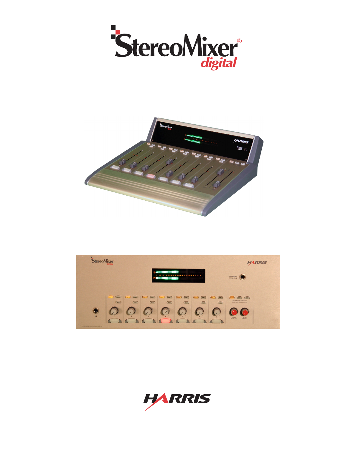
99-1396 Rack Version
99-1395 Desktop Version
Installation & Operation Guide

Revision C • 12/05
HARRIS CORPORATION
2
Thanks for joining the growing family of broadcasters
employing Harris Corporation products designed by PR&E. Our
mission is to provide the finest quality products, systems, docu-
mentation and after-sale support. To this end, we invite com-
ments and suggestions for improvements to this documentation
or to any of our services.
To obtain maximum benefit, please read through this guide
prior to mixer installation.
STEREOMIXER® DIGITAL OVERVIEW
StereoMixer®
digital
(SMX
d
) is a compact mixer available
in two models: rack-mount and desktop. SMX
d
was designed
for single talent/board operator use in applications such as
voice tracking studios, production rooms, nonlinear editing
suites and newsrooms. It has the following features:
• Four analog inputs (one input is mono), with a front panel
TRS stereo jack for convenient field recorder connection
• Three AES-3 digital inputs (S/PDIF-compatible) with
integral sample rate converters on each input
• Two Program buses and one mix-minus bus with both
analog and digital outputs
• Stereo bargraph meter display of the two program buses,
an External Monitor Input, or Cue
• Analog room monitor output, external talk input, talk
output, headphone amplifier output for talent headphones
• Room monitor mute logic plus opto-isolated interface
logic for a hot mic warning interface, intercom talk, mic
remote panel control, channel start command outputs
and timer reset output
• Audio and logic signals use separate connectors with AMP
MOD IV crimp terminal connectors (as used on the
BMX
digital
and RMX
digital
consoles) or D-sub (logic only)
Input Features
The mixer has seven inputs/channels. Four are analog, three
are digital. Rear panel switches set each analog input to either
-10 dBv (unbalanced) or +4 dBu (balanced) operation.
Channel 1 is a mono line-level input designed for a pre-
amplified talent mic. It can alternately be set as a mono line
input. Channels 2, 3 and 4 are analog stereo line-level inputs.
Channels 2 and 3 can alternately be set as two additional mic
inputs from guest microphone preamps. Internal DIPswitches
(identified on page 9) set whether ch. 1, 2 and/or 3 are mic
inputs (which mute the monitor output) or line inputs.
Channel 4 is an analog stereo line-level input that features
a front panelTRS jack to allow easy plug-in of a field recorder
or DJ system (which is summed with a rear panel connector).
Channels 5, 6 and 7 are stereo AES-3 digital inputs with
integral sample rate conversion that accepts sample rates from
32 to 48 kHz.
Any one channel can be set as a Telco input from a phone
hybrid,ISDN or other 2-way communications device.TheTelco
channel, set by internal DIPswitches (defined in Table 1 on
page 9), is always removed from the mix-minus output that is
returned to the Telco device.
Each of the seven input channels has these controls:
• Single channel On/Off button (lit by LEDs when On)
• Digital level control (linear faders on the desktop
version; rotary faders on the rack version)
• Function button (Talk on ch. 1, Cue on ch. 2 - 7)
• Program 1 and Program 2 bus assignment buttons
Output Features
The six analog outputs (+4 dBu balanced, -2 dBv unbal-
anced) are PGM 1, PGM 2, Room Monitor, Mix-Minus with
talk and Talk to External. The three digital outputs (PGM 1,
PGM 2, Mix-Minus) use a sample rate of 48 kHz (AES-3). An
amplified talent headphone output (1/4" TRS jack) has the
same monitor source as the Room Monitor output.
The Mix-Minus output is a sum of all the channels (post-
fader, post-switch) assigned to the same bus as the Telco chan-
nel—but minus the Telco channel audio. The mix-minus bus
is identified by the winking Telco bus assignment button. On
the left digital output and the analog output, talkback is added.
The digital right channel is a mix-minus without talk output.
Talkback audio is only active when channel 1 is set as a mic
input. Pressing the Talk button routes the mic—pre-switch
and pre-fader, to both the Talk output and to the Mix-Minus
with talk outputs.
Monitor Features
The monitor section has these controls:
• Monitor/meter source selectors (PGM 1, PGM 2, EXT)
• Digital level controls for the room monitor and talent
headphone outputs (linear faders on the desktop version;
rotary faders on the rack version)
The monitor outputs/meter can have four sources: Program
1, Program 2, an analog External Monitor input or Cue.
The Room Monitor and Headphones faders control the line-
level output for a pair of powered room monitor speakers and
General Information
3
Revision C • 12/05
HARRIS CORPORATION
the output level of the built-in headphone amplifier.The room
monitor output is automatically muted whenever a Mic chan-
nel is On (typically channel 1 is set as a mic, but channels 2
and 3 can also be set as mics).The talent/board operator head-
phone jack is next to the Channel 1 controls on the rack ver-
sion. It is inset into the left side panel on the desktop version.
Logic
The 2-way talk interface has External Talk audio and logic
inputs, a Talent/board operator Mic Talk output and Talk Out
Tally.These allow the SMX
d
to easily interface with any exist-
ing intercom system, or to function as its own talkback sys-
tem by adding an external audio switching relay.
There are three logic connectors on the rear panel:
•12-pin AMP MOD IV: Logic outputs for a warning
lamp interface, talk tally output and an external talk
logic input.
•14-pin AMP MOD IV: Logic inputs and outputs for
an optional cabinet-mount Mic Remote Panel
(PRE99-1197 or PRE99-1198) for channel 1 con-
trol from a remote talent mic location.
•15-pin female D-Sub: Ch. 2 - 7 start pulse outputs
and a timer reset command closure.
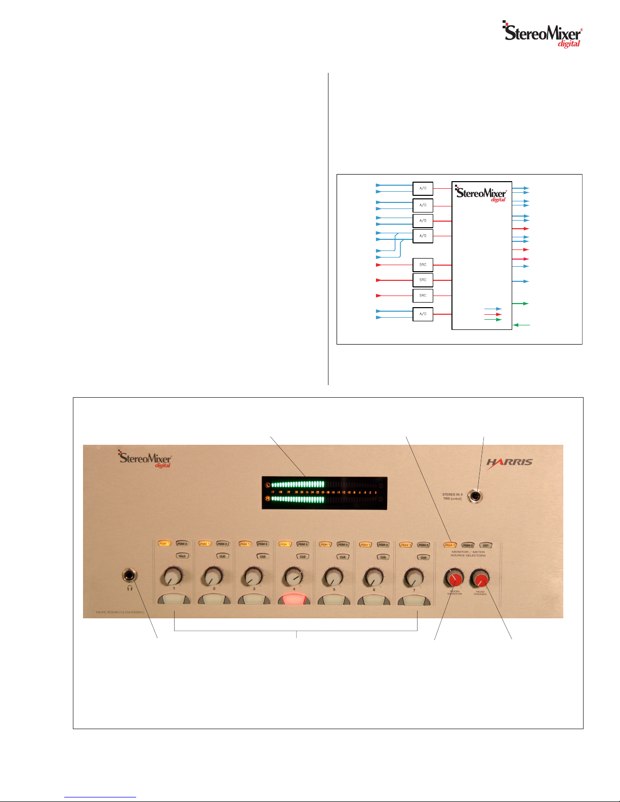
Overview of the Rack Mount model’s
Controls and Features
Stereo Bargraph Meter
(Displays average or
Average plus Peak)
Room Monitor
Output level
control
TRS Stereo Input
(alternate source
for Channel 4)
Talent
Headphones
level control
Channel controls (x7) with Bus
assign and Cue or Talk buttons, level
control & removable On/Off button lens
Meter, Monitor,
& Headphone
Source Selection
(Desktop model’s controls are shown on the next page)
Power Supply
A separate “line lump” switching power supply, with three
regulated output voltages, is supplied with both versions of
SMX
d
.The ±15 volt outputs power the analog circuitry, while
a +5 volt output powers the DSP and logic control circuits.
Talent
Headphones
Jack
Audio Routing
& Mixing DSP
Digital to Analog
Converters
Logic I/O
Stereo Bargraph Meter
MONO IN 1 *
AUX IN 4 STEREO
(Front Panel 1/4"TRS)
ANALOG IN 2L *
ANALOG IN 2R *
EXT.TALK
ANALOG IN 3L *
ANALOG IN 3R *
ANALOG IN 4L
ANALOG IN 4R
DIGITAL IN 5
DIGITAL IN 6
DIGITAL IN 7
EXT MONITOR IN L
EXT MONITOR IN R
EXT.TALLY LOGIC
(C/R Warning,Talk Tally,
Mic Panel Tallies, Start
Pulses,Timer Reset)
EXT. INPUT LOGIC
(Ext.Talk logic input,
Mic Panel Switches)
ROOM MONITOR OUT L
ROOM MONITOR OUT R
MIX MINUS OUT (DIGITAL)
MIX MINUS OUT (ANALOG)
PROGRAM 1 OUT L (ANALOG)
PROGRAM 1 OUT R (ANALOG
PROGRAM 1 OUT (DIGITAL)
TALKBACK OUT (ANALOG)
HEADPHONE AMP OUT L
HEADPHONE AMP OUT R
ANALOG AUDIO
DIGITAL AUDIO
LOGIC
PROGRAM 2 OUT L (ANALOG)
PROGRAM 2 OUT R (ANALOG
PROGRAM 2 OUT (DIGITAL)
* DIPSWITCH SET FOR MIC OR LINE FUNCTIONALITY
SRC:SAMPLE RATE CONVERSION
A/D:ANALOG TO DIGITAL CONVERSION
SMX
d
Block Diagram
Revision C • 12/05
HARRIS CORPORATION
4
SMX
d
uses a minimum of controls, lighted buttons and meter
displays to simplify mixer operation. Each of the two models:
rack-mount and desktop, offers identical functionality but with
different physical controls, as identified in this section.
For those used to working on larger Harris or PR&E mix-
ers and consoles, the SMX
d
’s major difference is that each
channel has only one button for On and Off control.When the
On/Off button LEDs are lit, the channel is on.When the On/
Off button LEDs are not lit, the channel is off.
The small Cue, Talk, Bus Assignment, and Monitor Source
Select buttons also light to indicate their selected status. To
assign a channel to a bus, press the bus assignment button to
turn on its LED. Each channel can be assigned to any combi-
nation of Program 1 (PGM 1) and Program 2 (PGM 2).
Three Monitor Source Select buttons select and indicate the
source feeding the meters, room monitor output and talent
headphones output. Only one button will be lit, although Cue,
when active on any channel, overrides the selection—turning
off the active button’s LED. The active Cue buttons wink to
indicate Cue is active. Turning all Cue buttons off returns the
monitor source to its previous selection. Alternately, to force
all Cue buttons off, press any monitor select button to assign
it as the new monitor source.
Both SMXd versions feature an unbalanced -10 dBv stereo
input TRS jack next to the meters (the Tip is the left channel,
the Ring is the right channel). It connects to Channel 4 along
with the rear panel channel 4 input. When both inputs are
active, the two signals are summed together.
Microphone Channels
Channel 1 is typically set as the Talent Mic. When On, the
room monitor output is muted and a“hot mic” warning com-
mand is activated. Pressing the Channel 1 Talk button routes
the mic audio (pre-fader and pre-switch) to the talk output
and to the mix-minus output.This action also mutes the room
monitor output, but it does not activate a warning command.
When Channels 2 and/or 3 are also set as mic inputs they
mute the room monitor output and generate a warning com-
mand when On. Their Cue button function also changes to
momentary operation and, while pressed, will mute the room
monitor output, without activating a warning command.
Note that only the Channel 1 mic can talk to the Mix-Mi-
nus signal and to the Talk output using the Channel 1 Talk
button. Channels 2 and/or 3 can talk to the Mix-Minus out-
put if they are assigned to the Mix-Minus bus and are turned
On with their fader up.
Telco Channel
Any one channel can be assigned as theTelco channel.This
means the channel’s input comes from a phone hybrid, ISDN,
or other two-way device that requires a return feed (the Mix-
Minus output, which is one bus minus the Telco channel au-
dio).The Mix-Minus output can be either the PGM 1 or PGM
2 bus. The bus feeding the Mix-Minus output is indicated by
winking the bus assignment button on the Telco channel.
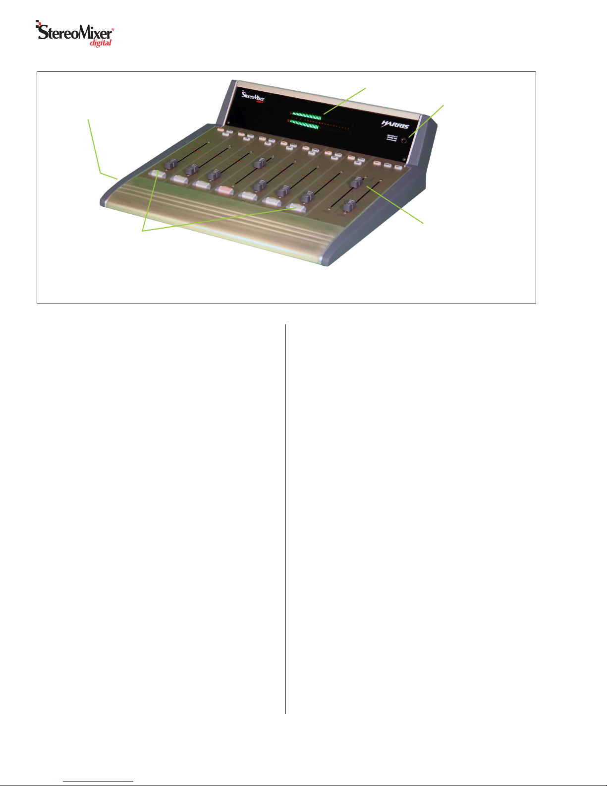
Overview of the Controls and Features
on the Desktop model
Stereo Bargraph Meter
TRS Input jack
for Input 4
Room Monitor & Talent
Headphones level
controls
Channel controls (x7)
with Bus assign and Cue
or Talk buttons, level
control & removable
On/Off button lens
Talent Headphones Jack
Mixer Operation
5
Revision C • 12/05
HARRIS CORPORATION
The PGM 1 bus has priority, but PGM 2 is used when the
Telco is only assigned to PGM 2. The Mix-Minus with talk
outputs always have talkback—even if the Telco channel is
not assigned to a bus.
Program Outputs
There are two Program outputs: Program 1 and Program
2. Each is a mix of all channels that are turned on and as-
signed to that bus.The Program outputs are never affected by
any incoming or outgoing talkback, by any monitor muting
(which occurs when any mic channel is on), by signal selec-
tion on the Monitor Select buttons, or by any Cue activity.
Each channel is independently assignable to either or both
program buses.The channel is assigned to a bus when its bus
assignment button is lit. But, in order for the channel audio to
reach the program bus, the channel must also be turned on
(On/Off button lit), and the fader must then be adjusted to
yield the proper audio level.
Monitor Controls
One Monitor Select button is lit to indicate the signal being
shown on the meters and being sent to the room monitor and
headphone outputs. Either PGM 1, PGM 2 or an external
monitor input (EXT) can be selected.
NOTE:When a microphone channel is on or theTalk button
is pressed, the room monitors mute, regardless of the selected
signal. Headphone audio is never muted.
Pressing any channel’s Cue button switches the monitor out-
puts and the meters to the Cue bus.To indicate the Cue bus is
active, the active Cue button(s) wink and the active Monitor
Select button LED is turned off. The Cue bus audio comes
from the channel’s input—it is pre-fader and pre-switch.
Turning all Cue buttons off returns the monitor to the pre-
viously selected source. Cue can also be forced off by pressing
any monitor select button to select a new monitor source.
Note that Channel 1 cannot be asigned to the Cue bus.
Talk / Intercom Operation
Press and hold the Talk button on Channel 1 to send the
talent’s microphone audio—pre-switch and pre-fader, to the
Talk output and to the Mix-Minus output, for as long as the
Talk button is pressed. This action mutes the Channel 1 mic
from any assigned bus (it automatically turns the channel off,
if it was on, while the Talk button is pressed).
When an external location talks to the SMX
d
, the incom-
ing talk audio is fed to both the headphones and to the room
monitor outputs. The monitor audio is dimmed by 12 dB so
the incoming talk can easily be heard.
BASIC MIXER OPERATION
Follow these steps to initially operate the mixer:
1. Adjust all faders (channels, room monitor and head-
phones) to full off.
2. Make sure that only the PGM 1 assignment buttons
are lit on each input channel and that the PGM 1 Moni-
tor Source selector button is lit.
3. Turn on one channel with a typical audio source con-
nected.
4.Adjust the channel fader so that the average audio level
bar reaches -18 to -12 dBFS on the meters. To reach
this level with a standard level signal the linear faders
are typically aligned with the red line. On rotary faders
the equivalent setting is at “two o’clock.”
5. To hear the audio, adjust the Room Monitor fader or
the Headphones fader to a comfortable listening level.
CAUTION: Before plugging in headphones, always
set the Headphones fader to full off, then adjust it
to a comfortable listening level using program ma-
terial with an average level of -18 to -12 dBFS.
NOTE: Setting the headphone fader beyond half-
way may supply sound pressure levels sufficiently
loud to damage headphones and cause hearing
damage, especially with sustained listening times.
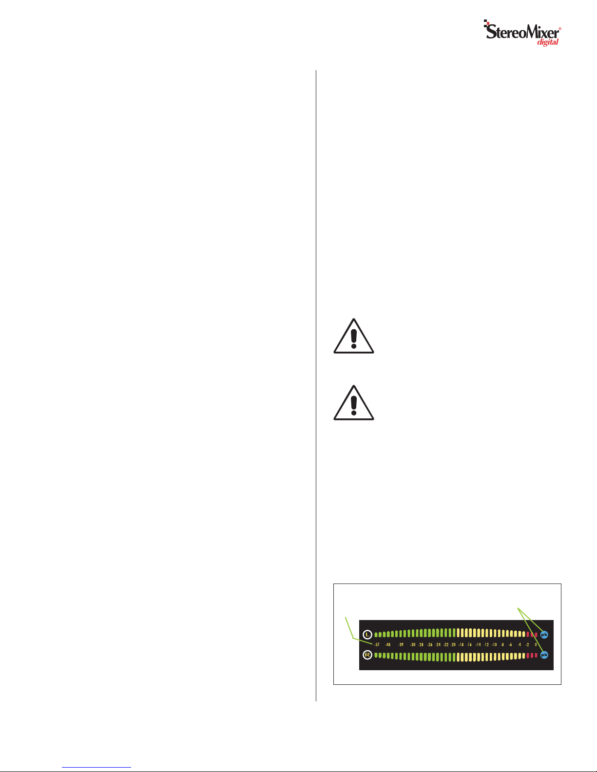
Peak Meter Indications
When the meters display both Average and Peak signals,
single LED peak indicators typically will be shown 10 dB
above the average levels. Peak indications in the yellow with
occasional red LED peaks are normal, but consistently allow-
ing signal peaks in the red LEDs should be avoided as this is
very close to overdriving the mixer.The blue peak LEDs indi-
cate the signal level is at or near signal clipping. They are set
to turn on at -6, -4, -2 or 0 dBFS via internal DIP switches.
SMX
d
Bargraph Meter
L = Left Channel Level &
R = Right Channel Level,
in dB below FSD*
Blue Peak Indicator
for each channel
* FSD = Full Scale Digital—the maximum mixer output level. -20 dBFS = 0 VU

Revision C • 12/05
HARRIS CORPORATION
6
The rack-mount model requires 4 RU of rack space (7"
[133.4mm]). There are no special venting requirements, so
equipment can be placed immediately above or below the
mixer.
The desktop model (shown in the Desktop Model Footprint
drawing, adjacent) requires 16" x 17" of countertop space.
One or more grommet holes can be drilled through the coun-
tertop for cable access behind the console. A removable rear
cable cover hides these cable access holes during use.The desk-
top model can also be fastened to the countertop by using
four screws (user supplied) fastened through bottom holes.
The SMX
d
installation kit includes a separate power sup-
ply, a 15-pin D-sub connector and the AMP MOD IV crimp
pins and housings for the audio and logic connectors.
Power Supply
A separate“line lump”power supply (Harris # 50-22) works
with line voltages from 95 to 264VAC at 50 Hz or 60 Hz.The
detachable IEC cord (supplied with USA-type plug) should
only be plugged into isolated-ground outlets. The keyed DC
output cable plugs into J32 (Power).
Ensure that the supply is mounted so that the DC cable
plugged into the SMX
d
is not under any tension.
USER CONNECTIONS
Most back panel user connections (shown on page 7) use
AMP MOD IV connectors, which consist of crimped recep-
tacle contacts locked into keyed plastic housings.These same
connectors are used on RMX
digital
and BMX
digital
consoles
and VistaMax Hub Cards.
NOTE: A crimp tool is not supplied with SMX
d
. Use an
AMP # 169481-1 crimp tool (Harris # 70-126) to crimp the
contacts. Use an AMP # 843477-3 pin removal tool (Harris #
70-129) to remove contacts from the housings. One each of
these tools is supplied with eachVistaMax frame, RMX
digital
console and BMX
digital
console. Contact Harris Tech Sup-
port (513.459.3503) about obtaining a crimp tool for use dur-
ing installation if one is not available locally.
Analog Audio Inputs & Outputs
The 6-pin AMP MOD IV analog audio connectors are pinned
the same as those used on RMX
digital
andBMX
digital
con-
soles. The left channel of a stereo pair connects to pins 1, 2
and 3.The right channel of a stereo pair connects to pins 4, 5
and 6.When a mono signal is connected to a stereo connector,
the two sets of signal pins must be jumpered together (- signal
to both 2 and 5, + signal to both 3 and 6). Only one shield
connection, to either pin 1 or 4, is required for mono signals.
Most analog connectors carry stereo signals, but two: J6
(Mic/Mono In and Ext.Talk In) and J9 (Mix-Minus and Talk
outputs) have two non-related mono signals on the same con-
nector.
Even though analog inputs and outputs are active and bal-
anced, unbalanced devices can connect to SMX
d
since there
is an analog gain switch for each input. For balanced signals,
set the switches to the +4 dBu position. For unbalanced de-
vices, set them to the -10 dBv position and then connect the
device using the following illustration.
Installation
Pinouts for Analog Input
and Output Connectors
Right High (+)
Right Low (-)
Shield
Left High (+)
Left Low (-)
Shield
3
2
1
6
5
4
(wire insertion end view)
Connecting an Unbalanced Device
to a MOD IV Analog Input
SMXd
Balanced
Input
From the
Unbalanced
Device
R
L
Shields
3
2
1
6
5
4
6.50
5.63
4x
11.25
0.25 HOLE
4.14
DESKTOP MODEL FOOTPRINT
16"
17"
Cable Access
Cutout area:2" x 12"
(Located below meter
panel and cable cover)
Countertop
Mounting Screw
Holes (x4 places)
7
Revision C • 12/05
HARRIS CORPORATION
When an unbalanced device must connect to a SMX
d
bal-
anced analog output, and an IHF-PRO match box is not avail-
able, do not tie the low (-) and shield pins together to“unbal-
ance”the signal. Leave the low output pin“floating” when un-
balancing a SMX
d
output, as shown in the following illustra-
tion.
Digital Audio Inputs & Outputs
The 3-pin AMP MOD IV digital audio connector pinouts
(shown at right, above) are pinned the same as those used on
the BMX
digital
and RMX
digital
consoles.
The digital inputs are J13 (Input 5), J14 (Input 6), and J15
(Input 7).The digital outputs are J16 (PGM 1), J17 (PGM 2),
and J18 (Mix-Minus).
The SMX
d
digital inputs can also handle most S/PDIF digi-
tal signals when a 249 ohm resistor is installed at the SMX
d
connector housing to load the 75 ohm S/PDIF cable. An un-
balanced-to-balanced line transformer could alternately be
used to interface an S/PDIF signal.
Note 1: A signal conversion interface must be used to con-
nect an AES/EBU output to a S/PDIF input.
Note 2: Some S/PDIF signals may not work with the SMX
d
’s
inputs, even with the additional load resistor or a transformer,
due to nonstandard levels or protocols used by the device with
the S/PDIF output.
SMXd
Balanced
Output
3
2
1
6
5
4
To the
Unbalanced
Device
R
L
Shields
Connecting an Unbalanced Device
to a MOD IV Analog Output
(Nominal Output is -2 dBu)
(Make no connections to pins 2 & 5)
Connecting an S/PDIF Device to
a MOD IV AES/EBU Input
249 ohm resistor
From
S/PDIF
Device
SMXd
AES/EBU
Input
Signal
Shield
3
2
1
Pinouts for Digital Input
and Output Connectors
High (+)
Low (-)
Shield
3
2
1
(wire insertion end view)
ANALOG INPUTS
DIGITAL INPUTS &
OUTPUTS
POWER SUPPLY
CONNECTION
START PULSE
OUTPUTS & TIMER
RESET OUTPUT
ANALOG OUTPUTS
C/R WARNING
& TALKBACK LOGIC
CHANNEL 1
MIC LOGIC
ANALOG INPUTS LEVEL
DIPSWITCHES
SMXD REAR PANEL CONNECTIONS
Revision C • 12/05
HARRIS CORPORATION
8
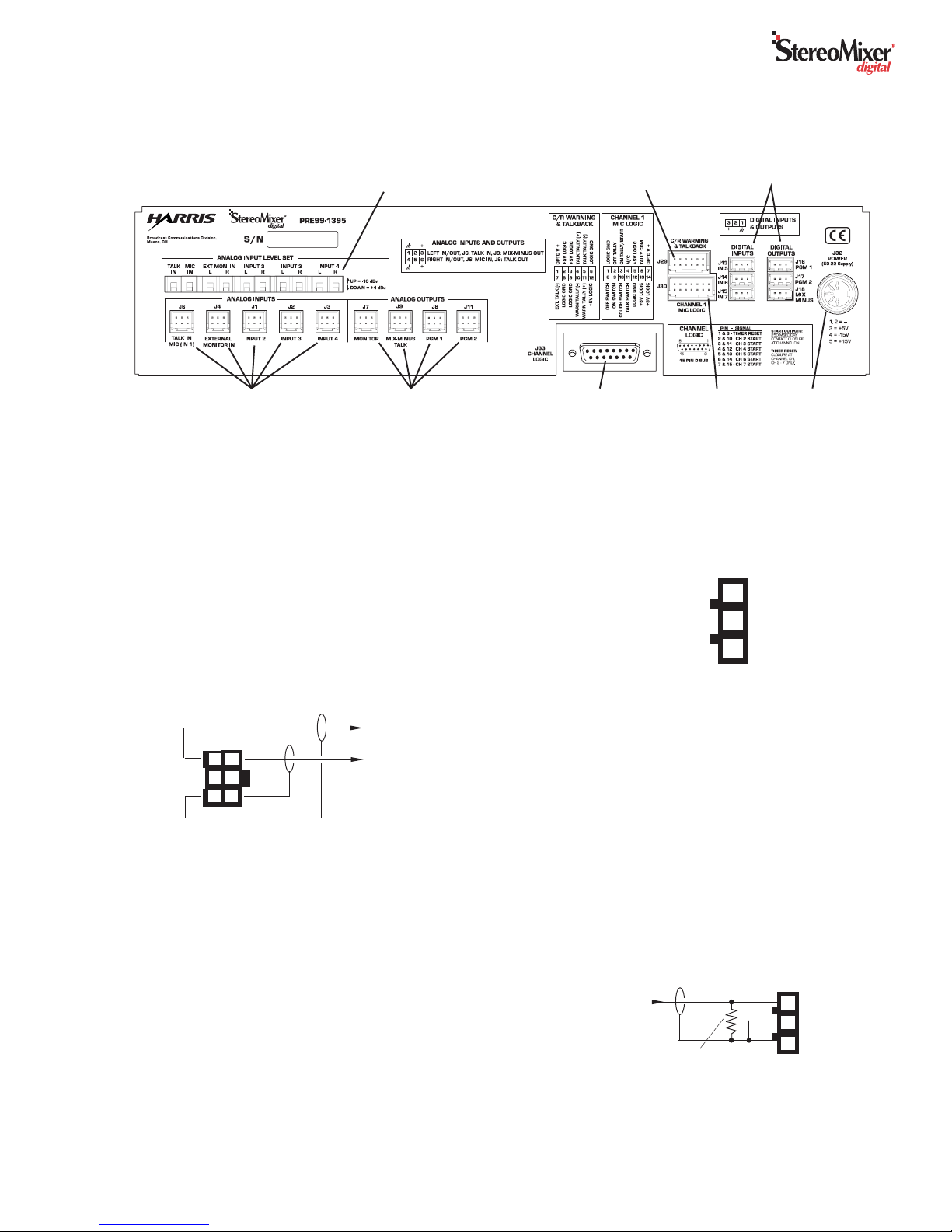
Logic Connections
There are three logic connectors on the SMX
d
:
• J29, a 12-pin AMP MOD IV connector, with the
warning tally output, talk tally output and external
talk logic input.
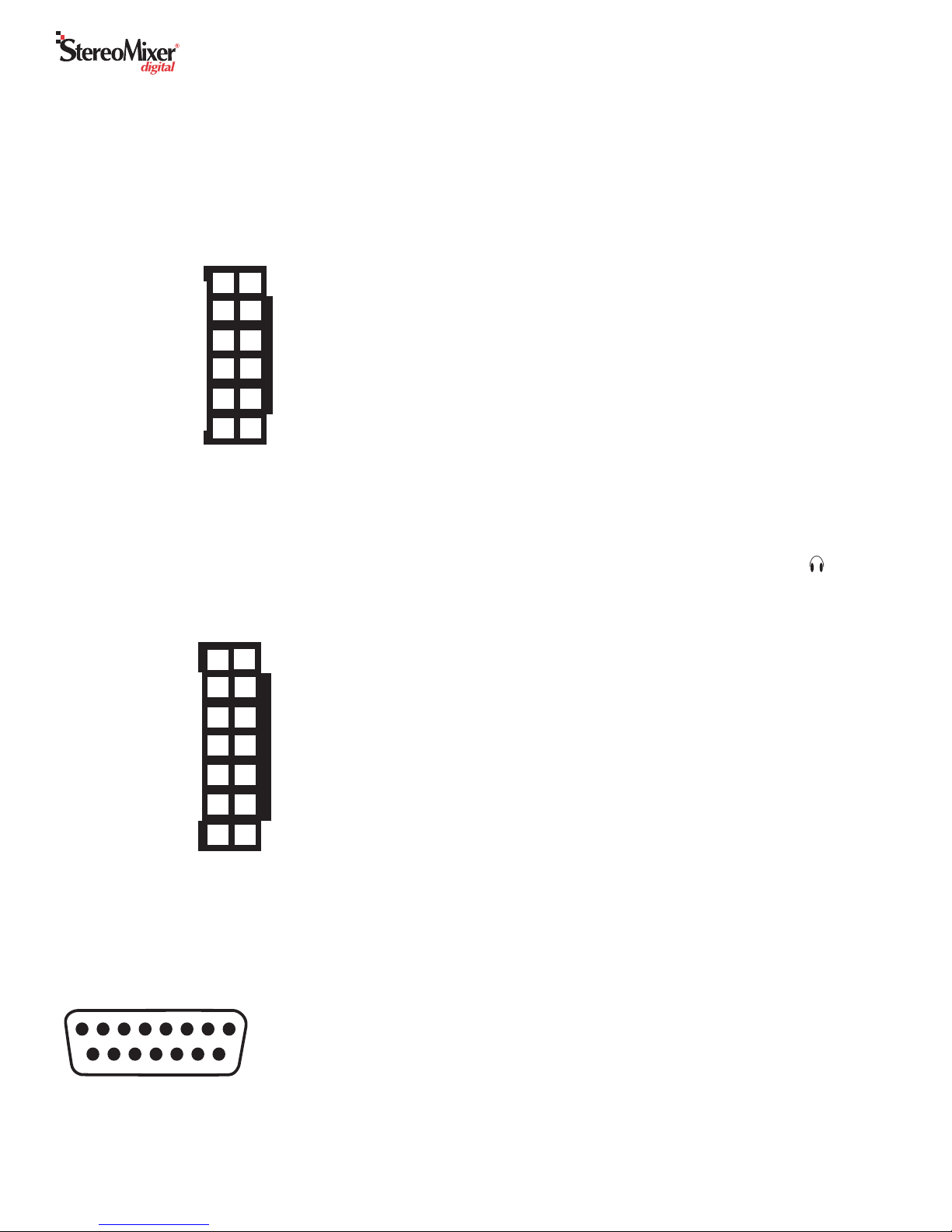
• J30, a 14-pin AMP MOD IV connector, for connect-
ing an optional Harris mic panel to control Channel
1. When a mic control panel is connected, it func-
tions in parallel with the front panel on/off and talk
buttons.
• J33, a 15-pin female D-sub connector, with Channel
2 - 7 start logic outputs and a timer reset output.
The J29 Tally outputs are solid-state versions of dry con-
tact relays. The two Warning Tally contacts are a sustained
contact closure while any Mic channel is On. The two Talk
Tally contacts are a sustained contact closure while the Talk
button is pressed on either channel 1 or the optional mic con-
trol panel. Each tally output can switch logic controls using
up to 60 VDC at 350 mA.
ExternalTalk (-) is a logic input, that when pulled low, while
Activate Ext. Talk (+) is connected to +5 volts, routes Exter-
nal Talk audio to the room monitor and headphone outputs.
J30 is used to plug in an optional Harris mic control panel
for remote control of the Channel 1 functions On, Off, Cough
andTalk at a remote mic location.The mic control panel func-
tions in parallel with the front panel buttons.
TRS Stereo Input & Headphones Output
There are two 1/4" unbalanced stereoTRS (Tip-Ring-Sleeve)
connectors on the front panel of the rack version. For both,
the Tip is the left channel, the Ring is the right channel and
Sleeve is ground. The STEREO IN 4 TRS jack is a -10 dBv
analog input for temporarily plugging in a portable stereo au-
dio device into Channel 4.The secondTRS jack (labeled to
the left of the channel 1 controls), is a standard stereo output
jack for the talent’s headphones.
On the desktop version, the TRS input jack (STEREO IN 4
TRS) is to the right of the meter display on the meter panel.
The talent’s headphone jack is inset in the left side panel, a
few inches back from the front left corner of the SMX
d
.
Note: The TRS input jack audio is summed with audio on
J3 (the Input 4 connector). Unless this is a desired function,
do not use J3 and the front panel TRS input simultaneously.
Typical Audio Connections and DIPswitch Settings
Connect the preamp output of the board operator/talent’s
mic to pins 4, 5, 6 of J6, Mic (In 1). Set internal DIPswitch
DS1-1 to on (on is toward the back panel).
One or two additional mic preamps can connected to in-
puts 2 or 3. When a mic is connected to J1 (Input 2), set
DIPswitch DS1-2 to on.When a mic is connected to J2 (Input
3), set DIPswitch DS1-3 to on.
Connect a Telco device (a phone hybrid, ISDN, or any 2-
way device that requires a mix-minus return signal) to any
available analog or digital input (analog inputs are J1, J2
and J3, digital inputs are J13, J14 and J15).
DIPswitches DS1-4, -5, -6 define which input is the Telco
channel per Table 1 on the next page. The return mix-minus
feed to the Telco device connects to pins 1, 2 and 3 of J9 (for
an analog return feed) or to J18 (for a digital return feed).
12-pin Warning and Talk Logic Connector
Ground
Talk Tally
Talk Tally
+5 Volts
+5 Volts
Activate Ext.Talk (+)
+5 Volts
Warning Tally
Warning Tally
Ground
Ground
External Talk (-)
6
5
4
3
2
1
12
11
10
9
8
7
14-pin Mic Remote Panel Logic Connector
Activate Logic (+)
Tallies Common
+5 Volts
N/C
On Tally
Off Tally
Ground
+5 Volts
+5 Volts
Ground
Talk Switch (-)
Cough Switch (-)
On Switch (-)
Off Switch (-)
7
6
5
4
3
2
1
14
13
12
11
10
9
8
15-pin Start & Timer Reset Logic Connector
8 7 6 5 4 3 2 1
15 14 13 12 11 10 9
1& 9 Timer Reset
2 & 10 - Ch 2 Start Pulse
3 & 11 - Ch 3 Start Pulse
4 & 12 - Ch 4 Start Pulse
5 & 13 - Ch 5 Start Pulse
6 & 14 - Ch 6 Start Pulse
7 & 15 - Ch 7 Start Pulse
8 - no connection

9
Revision C • 12/05
HARRIS CORPORATION
Connect analog or digital audio devices (CD players, rout-
ers, VistaMax outputs, recorders, etc.) to the remaining un-
used inputs (J1, J2 and J3 for analog devices; J13, J14 and
J15 for digital devices). If any analog devices use unbalanced
-10 dBv outputs, set the appropriate rear panel slide switch to
the -10 dBv position (see the rear panel drawing on page 7 for
switch setting details).
If a talkback system is being used, connect incoming talk
audio to pins 1, 2, 3 of J6. Connect the outgoing talk audio
wiring to pins 4, 5, 6 of J9.
Connect an analog External Monitor signal to J4 and con-
nect powered monitor speakers to J7. The Program 1 analog
stereo output is on J8 and the AES-3 digital output is on J16.
The Program 2 analog stereo output is on J11 and the AES-3
digital output is on J17.
Logic Interface
All logic inputs and outputs use the same type of circuits as
shown in block diagram form for J29, below. To activate in-
puts (like Ext. Talk on J29, pin 7), jumper the Activate (+)
input to a + voltage source (any +5Volts pin can be used with
an isolated control panel). On J29, pin 1 can be jumpered to
pin 2. Inputs are activated by a logic low, so a“Talk to SMX
d”
push switch (SPST) connects to pin 7 and 8 (Ground). The
Talk Tally output (pins 4 and 5) can be used to control an
audio relay for switching in the talk audio output (on J9) to
an external location.
Pins 10 and 11 connect to a dry-contact input warning lamp
interface (like the Harris WL-2). If the warning interface re-
quires high or low logic, and it is isolated, then J29 pin 12 (+5
Volts) or J29 pin 9 (Logic Ground) can be used to supply the
proper logic through J29 pins 10 or 11, otherwise source
ground or power from the warning lamp interface.
J33 has six 250 msec start command contact closures for
CD players and other remote-start devices. Channel 2 through
7 have separate outputs. Each output is identical to the Talk
Tally connection on J29 (a solid-state dry contact). There is
also a timer reset output, for resetting an event timer, on J33.
Internal DIPswitch DS2 Settings
DS2 has eight switches. DS2-1 thru -4 are not used in SMX
d
.
Table 2 (Peak Level Set), shown above, details the DS2 switch
settings.
DS2-5 and DS2-6 set the signal level where the blue peak
LEDs turn on.The default setting is 0 dB, but the level can be
set to 0, -2, -4, or -6 dB below full scale.
DS2-8 sets the meter display format.When DS2-8 is set to
on, then only the average audio level is shown (a solid bar
indicating average level).When DS2-8 is set to off (the default
setting) both average and peak indications are shown.
With DS2-8 set to off, DS2-7 becomes active. It sets whether
the peak indication is held for about one second, or whether it
immediately starts to decay. The peak indications always de-
cay at about 1 segment per 1/4 second.
To identify each channel’s source, remove the channel on/
off button lens by prying up on the top edge. Use clear label
tape or clear mylar to label the channels. Place the trimmed
mylar onto the buttoncap and snap the lens back in place. A
Word® template (Harris # 71-1961) is available for down-
loading at the customer support FTP site:
ftp://ftp.pre.com/
customer_support/RMXdigital_console
. Log in (username) is
customer. Password is pacific.
Notes:
Opto-Isolator inputs can handle +5 to +40 VDC logic
Opto-Isolator outputs can handle up to 60 volts or 350 mA
7
1
SMXd Internal Logic
Ext. Talk Command (-)
Activate Ext. Talk (+)
J29
J29
5Talk Tally
4Talk Tally
J29
J29
Ground
Ground
6
8
J29
J29
12
3
2+5 Volts
+5 volts
+5 Volts
+5 Volts
J29
J29
J29
Ground
9J29
10 WarningTally
11 Warning Tally
J29
J29
J29 Logic Block Diagram

Revision C • 12/05
HARRIS CORPORATION
10
Warranty
Safety Instructions
1. RR
RR
Read Aead A
ead Aead A
ead All Instrll Instr
ll Instrll Instr
ll Instrucuc
ucuc
uctionstions
tionstions
tions..... Read all safety and operating instructions before operating the product.
2. RR
RR
Retain Aetain A
etain Aetain A
etain All Instrll Instr
ll Instrll Instr
ll Instrucuc
ucuc
uctionstions
tionstions
tions..... Retain all safety and operating instructions for future reference.
3. HH
HH
Heed Aeed A
eed Aeed A
eed Allll
llll
ll WW
WW
Warar
arar
arningsnings
ningsnings
nings..... You must adhere to all warnings on the product and those listed in the operating instructions.
4. FF
FF
Folloollo
olloollo
ollow Aw A
w Aw A
w All Instrll Instr
ll Instrll Instr
ll Instrucuc
ucuc
uctionstions
tionstions
tions..... Follow all operating and product usage instructions.
5. HH
HH
Heaea
eaea
eatt
tt
t..... This product must be situated away from any heat sources such as radiators, heat registers, stoves, or other
products (including power amplifiers) that produce heat.
6. VV
VV
Venen
enen
entilatila
tilatila
tilation.tion.
tion.tion.
tion. Slots and openings in the product are provided for ventilation. They ensure reliable operation of the
product and keep it from overheating. Do not block or cover these openings during operation. Do not place this
product into a rack unless proper ventilation is provided and the manufacturer’s recommended installation
procedures are followed.
7. WW
WW
Waa
aa
att
tt
ter and Mer and M
er and Mer and M
er and Moisturoistur
oisturoistur
oisturee
ee
e..... Do not use this product near water such as a bathtub,wash bowl,kitchen sink,or laundry tub,
in a wet basement, or near a swimming pool or the like.
8. AA
AA
Attachmenttachmen
ttachmenttachmen
ttachmentsts
tsts
ts..... Do not use any attachments not recommended by the product manufacturer as they may cause
hazards.
9. PP
PP
Poo
oo
oww
ww
wer Ser S
er Ser S
er Sourour
ourour
ourcc
cc
ceses
eses
es
..... You must operate this product using the type of power source indicated on the marking label and
in the installation instructions. If you are not sure of the type of power supplied to your facility, consult your local
power company.
10. GG
GG
Grr
rr
rounding and Pounding and P
ounding and Pounding and P
ounding and Polarolar
olarolar
olarizaiza
izaiza
ization.tion.
tion.tion.
tion. This product is equipped with a polarized AC plug with integral safety ground pin.
Do not defeat the safety ground in any manner.
11. PP
PP
Poo
oo
oww
ww
wer Cer C
er Cer C
er Coror
oror
ord Pd P
d Pd P
d Prr
rr
rotot
otot
otecec
ecec
ection.tion.
tion.tion.
tion. Power supply cords must be routed so that they are not likely to be walked on nor pinched
by items placed upon or against them. Pay particular attention to the cords at AC wall plugs and convenience
receptacles, and at the point where the cord plugs into the product.
12. LighLigh
LighLigh
Lightningtning
tningtning
tning..... For added protection for this product, unplug it from the AC wall outlet during a lightning storm or
when it is left unattended and unused for long periods of time. This will prevent damage to the product due to
lightning and power line surges.
13. OO
OO
Ovv
vv
verer
erer
erloadingloading
loadingloading
loading..... Do not overload AC wall outlets,extension cords,or integral convenience outlets as this can result in
a fire or electric shock hazard.
14. OO
OO
Objecbjec
bjecbjec
bject and Liquid Et and Liquid E
t and Liquid Et and Liquid E
t and Liquid Enn
nn
ntrtr
trtr
tryy
yy
y..... Never push objects of any kind into this product through openings as they may touch
dangerous voltage points or short out parts, which could result in a fire or electric shock. Never spill liquid of any
kind on the product.
15. AA
AA
Acccc
cccc
ccessoressor
essoressor
essoriesies
iesies
ies..... Do not place this product on an unstable cart, stand, tripod, bracket, or table. The product may fall,
causing serious injury to a child or adult and serious damage to the product. Any mounting of the product must
follow manufacturer’s installation instructions.
16. PP
PP
Prr
rr
roo
oo
oducduc
ducduc
duct and Ct and C
t and Ct and C
t and Carar
arar
art Ct C
t Ct C
t Combinaombina
ombinaombina
ombination.tion.
tion.tion.
tion. Move this product with care. Quick stops, excessive force, and uneven surfaces
may cause the product and the cart combination to overturn.
17. SS
SS
Serer
erer
ervicingvicing
vicingvicing
vicing..... Refer all servicing to qualified servicing personnel.
18. DD
DD
Damage Ramage R
amage Ramage R
amage Requirequir
equirequir
equiring Sing S
ing Sing S
ing Serer
erer
ervicvic
vicvic
vicee
ee
e..... Unplug this product from the wall AC outlet and refer servicing to qualified service
personnel under the following conditions:
a.When the AC cord or plug is damaged.
b. If liquid has been spilled or objects have fallen into the product.
c.If the product has been exposed to rain or water.
d. If the product does not operate normally (following operating instructions).
e.If the product has been dropped or damaged in any way.
f. When the product exhibits a distinct change in performance.This indicates a need for service.
19. RR
RR
Replaceplac
eplaceplac
eplacemenemen
emenemen
ement Pt P
t Pt P
t Parar
arar
artsts
tsts
ts
..... When replacement parts are required, be sure the service technician has used replacement
parts specified by the manufacturer or that have the same characteristics as the original parts. Unauthorized
substitutions may result in fire, electric shock, or other hazards.
20. SS
SS
Safaf
afaf
afetet
etet
ety Cy C
y Cy C
y Check.heck.
heck.heck.
heck. Upon completion of any repairs to this product, ask the service technician to perform safety checks
to determine that the product is in proper operating condition.
21. CC
CC
Cleaningleaning
leaningleaning
leaning..... Do not use liquid or aerosol cleaners. Use only a damp cloth for cleaning.
NONO
NONO
NOTE:TE:
TE:TE:
TE:
This equipment has been tested and found to comply with the limits for a Class A digital device,
pursuant to part 15 of the FCC Rules. These limits are designed to provide reasonable protection against
harmful interference when the equipment is operated in a commercial environment. This equipment gener-
ates, uses, and can radiate radio frequency energy and, if not installed and used in accordance with the in-
struction manual, may cause harmful interference to radio communications. Operation of this equipment in
a residential area is likely to cause harmful interference in which case the user will be required to correct the
interference at his own expense.
Hazard/Warning Labels
The LighLigh
LighLigh
Lightning Ftning F
tning Ftning F
tning Flashlash
lashlash
lash WW
WW
With Aith A
ith Aith A
ith Arr
rr
rrr
rr
roo
oo
owhead symbwhead symb
whead symbwhead symb
whead symbolol
olol
ol, within an equilateral
triangle, alerts the user to the presence of uninsulated dangerous voltage
within the product’s enclosure that may be of sufficient magnitude to
constitute a risk of electric shock.
The EE
EE
Exx
xx
xclamaclama
clamaclama
clamation Ption P
tion Ption P
tion Poinoin
oinoin
oint symbt symb
t symbt symb
t symbolol
olol
ol, within an equilateral triangle,alerts the
user to the presence of important operating and maintenance (servicing)
instructions in product literature and instruction manuals.
StereoMixer® digital carries a manufacturer’s warranty subject to the following guidelines and limitations:
A) Except as expressly excluded herein, Harris Corporation (“Seller”) warrants equipment of its own manu-
facture against faulty workmanship or the use of defective materials for a period of one (1) year from
date of shipment to Buyer. The liability of the Seller under this Warranty is limited to replacing, repair-
ing, or issuing credit (at the Seller’s discretion) for any equipment, provided that Seller is promptly
notified in writing within five (5) days upon discovery of such defects by Buyer, and Seller’s examination
of such equipment shall disclose to its satisfaction that such defects existed at the time shipment was
originally made by Seller, and Buyer returns the defective equipment to Seller’s place of business in
Mason, Ohio, packaging and transportation prepaid, with return packaging and transport guaranteed.
B) Equipment furnished by Seller, but manufactured by another, shall be warranted only to the extent
provided by the other manufacturer.
C) Thermal filament devices, such as fuses, are expressly excluded from this warranty.
D) The warranty period on equipment or parts repaired or replaced under warranty shall expire upon the
expiration date of the original warranty.
E) This Warranty is void for equipment which has been subject to abuse, improper installation, improper
operation, improper or omitted maintenance, alteration, accident, negligence (in use, storage, transpor-
tation, or handling), operation not in accordance with Seller’s operation and service instructions, or
operation outside of the environmental conditions specified by Seller.
F) This Warranty is the only warranty made by Seller, and is in lieu of all other warranties, including
merchantability and fitness for a particular purpose, whether expressed or implied, except as to title
and to the expressed specifications contained in this manual. Seller’s sole liability for any equipment
failure or any breach of this Warranty is as set forth in subparagraph A) above; Seller shall not be liable
or responsible for any business loss or interruption, or other consequential damages of any nature
whatsoever, resulting from any equipment failure or breach of this warranty.
Specifications
Test Conditions: FSD=Full Scale Digital, +24 dBu. Specifications are per channel, analog outputs with
600 ohm loads. 0 dBu equals 0.775 V RMS, regardless of circuit impedance (=0 dBm into a 600 ohm
circuit). Noise measurements use 22 kHz BW (add 1.7 dB with a 30 kHz BW). Total Harmonic
Distortion (THD + Noise) measured at +18 dBu using a 1 kHz signal or a swept signal with a 22 kHz
low pass filter.
Analog Inputs & Outputs
Input Impedance:
>40k, balanced
Nominal Input Levels:
-10 dBv or +4 dBu (DIP switch set)
Maximum Input Level:
+24 dBu
Output Source Impedance:
<3 ohms, balanced
Output Load Impedance:
1k ohm, minimum
Nominal Output Level:
+4 dBu
Maximum Output Level:
+24 dBu
Digital Inputs & Outputs
Reference:
-20 dB FSD (equivalent to a +4 dBu analog level)
Signal Format:
AES-3, S/PDIF (input only)
AES-3 Input Compliance:
24-bit with sample rate conversion on all inputs
AES-3 Output Compliance:
24-bit
Digital Reference Frequency:
Internal crystal
Internal and Output Sample Rate:
48 kHz
Mixing & Conversion
Processing Resolution:
24-bit fixed with external precision accumulators
Conversions:
A/D 24-bit Delta-Sigma, 128x oversampling on digital inputs; D/A 24-bit,
Delta-Sigma, 128x oversampling.
Latency:
<1.6 ms, analog input to analog output; <300 µs digital in to digital out
Frequency Response & Dynamic Range
Analog In to Analog Out:
+0 dB/-0.65 dB, 20 Hz to 20 kHz
Analog In to Analog Out:
101 dB, 104 dB “A”weighted (both referenced to FSD)
Analog In to Digital Out:
104.5 dB (referenced to FSD)
Digital In to Analog Out:
103.5 dB, 106.5 dB “A” weighted (both referenced to FSD)
Digital Input to Digital Output:
115 dB
Total Harmonic Distortion + Noise
Analog Input to Analog Output:
<0.003%, @ 1 kHz, +18 dBu input and output,
22 kHz filter bandwidth
Digital Input to Digital Output:
<0.0005%, @ 1 kHz, -6 dB FSD input and output,
20 kHz filter bandwidth
Digital Input to Analog Output:
<0.002%, @ 1 kHz, -6 dB FSD input, +18 dBu output,
22 kHz filter bandwidth
Crosstalk Isolation and Left/Right Separation
Isolation between any analog inputs or outputs:
>80 dB, 20 Hz - 20 kHz; > 96 dB @ 1 kHz
Separation:
>86 dB
Power Supply
Type: External, multiple output (+15, -15, +5)
Input AC voltage:
95 - 264VAC, 50/60 Hz (auto-input voltage sensing)
AC input:
IEC power cord
Cooling: Convection cooled, no fans
Dimensions
SMXd Rack-Mount: 7" x 19.0" x 3.0" (H,W, D) (4 RU)
SMXd desktop: 4" x 16" x 17" (H,W, D)
Harris Corporation reserves the right to change specifications without notice or obligation.
RISK OF ELECTRIC SHOCK
DO NOT OPEN
CAUTION
WARNING: SHOCK HAZARD - DO NOT OPEN
AVIS: RISQUE DE CHOC ELECTRIQUE - NE PAS OUVRIR
CAUTION: TO REDUCE THE RISK OF ELECTRIC SHOCK DO NOT
REMOVE ANY COVER OR PANEL. NO USER SERVICEABLE PARTS
INSIDE. REFER SERVICING TO QUALIFIED SERVICE PERSONNEL.
WARNING: TO REDUCE THE RISK OF FIRE OR ELECTRIC SHOCK, DO
NOT EXPOSE THE POWER SUPPLY OR MIXER TO RAIN OR MOISTURE.
This manual suits for next models
1
Table of contents
Other Harris Music Mixer manuals


