Harrop TVS1320 User manual
HARROPPERFORMANCE HARROPTV W: HARROP.COM.AU P: 1300 HARROP E: SALES@HARROP.COM.AU
HARROPPERFORMANCE HARROPTV W: HARROP.COM.AU P: 1300 HARROP E: SALES@HARROP.COM.AU
ENGINEERING PERFORMANCE SINCE 1955
HARROPPERFORMANCE HARROPTV W: HARROP.COM.AU P: 1300 HARROP E: SALES@HARROP.COM.AU
Issue 4: June 2021
Installation Guide
Toyota 86/ Subaru BRZ
TVS1320 Supercharger Kit

HARROPPERFORMANCE HARROPTV W: HARROP.COM.AU P: 1300 HARROP E: SALES@HARROP.COM.AU
HARROPPERFORMANCE HARROPTV W: HARROP.COM.AU P: 1300 HARROP E: SALES@HARROP.COM.AU
1
TVS1320 INSTALLATION GUIDE
ENGINEERING PERFORMANCE SINCE 1955
ENGINEERING PERFORMANCE SINCE 1955
For 60 years Harrop Engineering has been at the forefront of designing, developing and
manufacturing precision performance components. Today our innovative and logical approach
is applied to low volume automotive OEMs and the performance aftermarket through
a dedicated team of 65 sta. Core performance products include Superchargers, Engine
Components, Brakes, Dierentials and we are also the exclusive Australian Distributor for
Forgeline Motorsport Wheels & Lingenfelter Performance Parts.
Harrop are also the preferred supplier of Eaton Supercharger and Traction Control technology
including dual branded product designed and manufactured in-house. There are currently over
4000 components in our portfolio and this is growing daily as we continually develop more
Harrop Performance Products.
Our high prole car manufacturing customers include Holden, HSV, FPV, Roush and Lotus.
We also supply to race teams from categories including F1, NASCAR and V8 Supercars and an
extensive range of drag, circuit and o-road competitors. Just as importantly, a large portion of
our customers are performance enthusiasts and weekend warriors who are highly passionate
about their ride.
Please take a moment to review the following pages and learn why Harrop is the rst choice in
Superchargers.
Thank you for choosing Harrop and enjoy your Harrop Enhanced ride.
- Team HARROP
HARROPPERFORMANCE HARROPTV W: HARROP.COM.AU P: 1300 HARROP E: SALES@HARROP.COM.AU
HARROPPERFORMANCE HARROPTV W: HARROP.COM.AU P: 1300 HARROP E: SALES@HARROP.COM.AU
HARROPPERFORMANCE HARROPTV W: HARROP.COM.AU P: 1300 HARROP E: SALES@HARROP.COM.AU
TVS1320 INSTALLATION GUIDE
CONTENTS PAGE
ENGINEERING PERFORMANCE SINCE 1955
Introduction 1
Table of contents 2
Important information / warranty information 3
Remove Ancillaries 4
Remove Sound Tube & Intake Manifold 5
Supercharger Pre Installation 8
Supercharger Installation 11
Rear A/C line clearance 14
Throttle body installation 14
Idler and belt installation 15
Air box installation 16
Intercooler system installation 17
Intercooler pump wiring 21
Intercooler system lling and bleeding 23
Pre start up checks 24
HARROPPERFORMANCE HARROPTV W: HARROP.COM.AU P: 1300 HARROP E: SALES@HARROP.COM.AU
2

HARROPPERFORMANCE HARROPTV W: HARROP.COM.AU P: 1300 HARROP E: SALES@HARROP.COM.AU
HARROPPERFORMANCE HARROPTV W: HARROP.COM.AU P: 1300 HARROP E: SALES@HARROP.COM.AU
TVS1320 INSTALLATION GUIDE
ATTENTION: READ BEFORE PROCEEDING
ENGINEERING PERFORMANCE SINCE 1955
Important information:
The owner and driver of the enhanced vehicle must be aware that tment of a supercharger may aect:
• The vehicle’s factory warranty.
• Insurance cover and associated liabilities.
• Compatibility with emission and roadworthy certication.
• The validity of a driver’s license for a supercharged vehicle.
• The handling & braking capability of the vehicle due to increased engine power & torque
• The longevity of the engine and driveline components.
• The vehicle will need to use premium unleaded fuel only (98 RON).
• Coolant used in the intercooler system must adhere to Ford WSS-M97B44-D or GMW3420
specication mixed 50% concentrate with distilled or deionised water.
Warranty:
This supercharger is covered by a limited warranty on components and workmanship for a period of 36
months from the date of purchase, subject to Harrop terms and conditions.
Please refer to Harrop Engineering’s full warranty terms and conditions and applicable warranty
registration forms which can be found at www.harrop.com.au.
HARROPPERFORMANCE HARROPTV W: HARROP.COM.AU P: 1300 HARROP E: SALES@HARROP.COM.AU
3

HARROPPERFORMANCE HARROPTV W: HARROP.COM.AU P: 1300 HARROP E: SALES@HARROP.COM.AU
HARROPPERFORMANCE HARROPTV W: HARROP.COM.AU P: 1300 HARROP E: SALES@HARROP.COM.AU
TVS1320 INSTALLATION GUIDE
QUICK START GUIDE FOR EXPERIENCED AUTOMOTIVE TECHNICIANS
ENGINEERING PERFORMANCE SINCE 1955
This document is meant only as a guide, as any vehicle modication should be completed by a
certied technician who has the relevant experience and equipment to be competent of a safe
and eective supercharger installation.
If you have purchased a complete kit (including ECUTEK cable, license and calibration)
follow the steps below before starting the installation. This will ensure you receive the
correct ROM le for your vehicle.
i. Go to the ECUTEK website. www.ecutek.com/support/downloads
ii. Go to the ECUTEK App downloader tab and follow the instructions for installing the drivers for
the license key and vehicle interface and also the software specic for your license key
iii. Once installed refer to the ProECU Programming guide located in ProECU help les
iv. Follow the process to the step “Query ECU”on page 5 of the programming manual
v. Once the ECU has been queried send the ECU Version to sales@harrop.com.au
vi. You will then receive the correct versioned ROM for your supercharger installation
Please ensure the safe operation of all tools and equipment are adhered to in accordance
with the vehicle and equipment manufacture’s recommendation.
1. Ensure the vehicle is prepared with premium (98 RON) unleaded fuel
1.a. Disconnect the negative terminal of the battery.
1.b. Avoid standing the supercharger on its end, as the oil in the gear housing may migrate from
the intended area.
2. Remove ancillaries (intake tube, air box, lter, covers, strut braces and belt)
2.a. Remove Inlet tube.
2.b. Remove Air box.
2.c. Remove MAF sensor from air box.
2.d. Remove covers from alternator and A/C compressor.
2.e. Use 14mm socket on tensioner and remove belt.
2.f. Remove strut braces.
HARROPPERFORMANCE HARROPTV W: HARROP.COM.AU P: 1300 HARROP E: SALES@HARROP.COM.AU
4
HARROPPERFORMANCE HARROPTV W: HARROP.COM.AU P: 1300 HARROP E: SALES@HARROP.COM.AU
HARROPPERFORMANCE HARROPTV W: HARROP.COM.AU P: 1300 HARROP E: SALES@HARROP.COM.AU
TVS1320 INSTALLATION GUIDE
QUICK START GUIDE FOR EXPERIENCED AUTOMOTIVE TECHNICIANS
ENGINEERING PERFORMANCE SINCE 1955
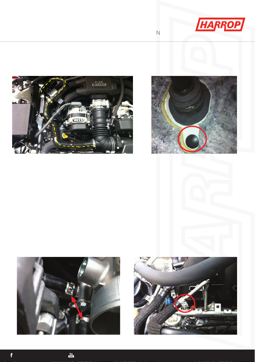
3. Sound tube removal
3.a. Remove sound tube assembly as shown below.
3.b. Install supplied blanking grommet to the hole left in the rewall. Drivers side (RHD)
passenger side (LHD) inner foot well.
4. Remove intake manifold
4.a. Remove cover from the top of the manifold.
4.b. Disconnect the vacuum hoses from the rear of the intake manifold.
4.c. Disconnect wiring (MAP sensor, Throttle body).
4.d. Remove fuel rail covers and unbolt the ECU from the RH cover (this will sit beside the
engine while you work).
4.e. Remove port injector harnesses x 4 and unclip harness from fuel rail assembly.
4.f. Remove wiring harness from rear of intake manifold (EVAP solenoid).
4.g. Remove throttle body heater hoses (Caution - do not remove when vehicle is hot, requires
clamping while working).
4.h. Remove the throttle body from inlet manifold.
4.i. Disconnect the fuel line (Caution – use eye protection when disconnecting fuel system lines
as they will contain fuel and may have some residual fuel pressure. Do not disconnect the fuel
supply line immediately after running the vehicle or when the vehicle is hot).
3.b
4.g 4.i
HARROPPERFORMANCE HARROPTV W: HARROP.COM.AU P: 1300 HARROP E: SALES@HARROP.COM.AU
5
3.a

HARROPPERFORMANCE HARROPTV W: HARROP.COM.AU P: 1300 HARROP E: SALES@HARROP.COM.AU
HARROPPERFORMANCE HARROPTV W: HARROP.COM.AU P: 1300 HARROP E: SALES@HARROP.COM.AU
TVS1320 INSTALLATION GUIDE
QUICK START GUIDE FOR EXPERIENCED AUTOMOTIVE TECHNICIANS
ENGINEERING PERFORMANCE SINCE 1955
4.j. Disconnect the fuel crossover pipe from both fuel rails.
4.k. Remove the fuel rail support bolt from the LH fuel rail.
4.l. Remove the EVAP purge hose from the fuel rail tting.
HARROPPERFORMANCE HARROPTV W: HARROP.COM.AU P: 1300 HARROP E: SALES@HARROP.COM.AU
6
HARROPPERFORMANCE HARROPTV W: HARROP.COM.AU P: 1300 HARROP E: SALES@HARROP.COM.AU
HARROPPERFORMANCE HARROPTV W: HARROP.COM.AU P: 1300 HARROP E: SALES@HARROP.COM.AU
TVS1320 INSTALLATION GUIDE
QUICK START GUIDE FOR EXPERIENCED AUTOMOTIVE TECHNICIANS
ENGINEERING PERFORMANCE SINCE 1955
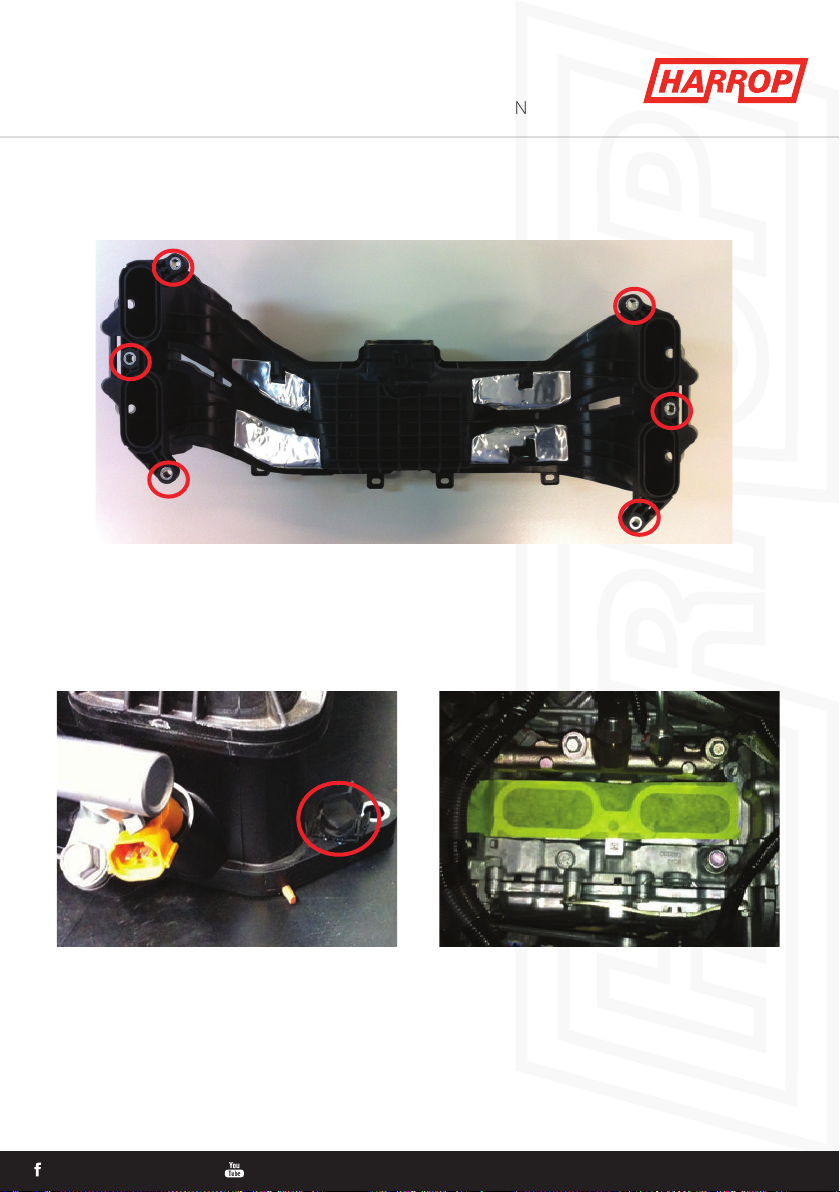
4.m. Remove 6 intake manifold bolts and remove intake manifold (picture of manifold from the
underneath side shown for clarity of bolt locations). Note engine harnesses on RH rear and LH
front need to be pushed aside to access bolt heads.
4.n. Unclip loom from LH rear lug on manifold.
4.o. Cover intake ports with tape while working on and around the engine bay.
4.p. Remove EVAP solenoid from underside of intake manifold.
4.q. Remove the MAP sensor from the manifold.
4.m
4.o4.n
HARROPPERFORMANCE HARROPTV W: HARROP.COM.AU P: 1300 HARROP E: SALES@HARROP.COM.AU
7

HARROPPERFORMANCE HARROPTV W: HARROP.COM.AU P: 1300 HARROP E: SALES@HARROP.COM.AU
HARROPPERFORMANCE HARROPTV W: HARROP.COM.AU P: 1300 HARROP E: SALES@HARROP.COM.AU
TVS1320 INSTALLATION GUIDE
QUICK START GUIDE FOR EXPERIENCED AUTOMOTIVE TECHNICIANS
ENGINEERING PERFORMANCE SINCE 1955
5. Supercharger Pre-installation
5.a. Install Throttle body heater blanking plugs.
5.b. Remove brake booster hard line if applicable (RHD). Note: If vehicle is auto and is tted with
a vacuum pump, skip this step.
5.c. Install EVAP solenoid to supercharger manifold using the original nut and connect lines as
shown (use 14mm Cobra clamp).
Note: For vehicles tted with a seperate vacuum pump for the brake booster, t the supplied
cap and cobra clamp as shown and disregard hose marked in image 5.c.
5.a 5.a
5.b 5.c
HARROPPERFORMANCE HARROPTV W: HARROP.COM.AU P: 1300 HARROP E: SALES@HARROP.COM.AU
8

HARROPPERFORMANCE HARROPTV W: HARROP.COM.AU P: 1300 HARROP E: SALES@HARROP.COM.AU
HARROPPERFORMANCE HARROPTV W: HARROP.COM.AU P: 1300 HARROP E: SALES@HARROP.COM.AU
5.d. Install PCV breather line (under A/C compressor).
5.e. Move the grey loom and zip tie as shown. (remove connector from metal bracket to slip
loom behind it).
5.f. Install supplied throttle, MAP, MAF loom and route as shown (connect the supplied loom to
the standard connectors and zip tie IAT loom to breather hose behind A/C compressor, throttle.
TVS1320 INSTALLATION GUIDE
QUICK START GUIDE FOR EXPERIENCED AUTOMOTIVE TECHNICIANS
ENGINEERING PERFORMANCE SINCE 1955
5.d
5.e
5.f
5.f
HARROPPERFORMANCE HARROPTV W: HARROP.COM.AU P: 1300 HARROP E: SALES@HARROP.COM.AU
9

HARROPPERFORMANCE HARROPTV W: HARROP.COM.AU P: 1300 HARROP E: SALES@HARROP.COM.AU
HARROPPERFORMANCE HARROPTV W: HARROP.COM.AU P: 1300 HARROP E: SALES@HARROP.COM.AU
5.g. Remove the fuel rail bolts x 4, fuel rails, fuel injectors and seals (be sure the injector seals are
removed from the standard manifold as they sometime stick in the manifold when removing
the injector, its easiest if these seals are removed from the injectors and installed into the SC
manifold for assembly) from the standard manifold and reinstall on the supercharger manifold
(fuel rail bolt torque 19N.m) Note injector keying, blue circles.
5.h. Install the MAP sensor into the supercharger manifold & secure using M5 screw provided.
5.i. Remove standard manifold rubber gaskets from standard manifold and install into
supercharger manifold (ensure manifold faces are clean and avoid sliding the supercharger
assembly on the seals after installation as this will damage the seals).
TVS1320 INSTALLATION GUIDE
QUICK START GUIDE FOR EXPERIENCED AUTOMOTIVE TECHNICIANS
ENGINEERING PERFORMANCE SINCE 1955
5.g 5.g
5.g 5.g
5.h 5.i
HARROPPERFORMANCE HARROPTV W: HARROP.COM.AU P: 1300 HARROP E: SALES@HARROP.COM.AU
10

HARROPPERFORMANCE HARROPTV W: HARROP.COM.AU P: 1300 HARROP E: SALES@HARROP.COM.AU
HARROPPERFORMANCE HARROPTV W: HARROP.COM.AU P: 1300 HARROP E: SALES@HARROP.COM.AU
TVS1320 INSTALLATION GUIDE
QUICK START GUIDE FOR EXPERIENCED AUTOMOTIVE TECHNICIANS
ENGINEERING PERFORMANCE SINCE 1955
6. Supercharger installation
6.a. Ensure that the engine looms and hoses are clear from the intake ports / manifold face
and the front center section of the engine. (Note: ensure main cross over loom is sitting at as
height between SC and loom is limited).
6.b. Install the fuel crossover pipe as shown.
6.c. Remove tape from the inlet engine ports. Inspect Supercharger manifold assembly includ-
ing the ports to ensure there is no foreign objects or debris.
6.d. Using 2 people lower the supercharger manifold onto the engine. Avoid sliding the
manifold across the heads as this may damage the manifold seals.
6.e. Once the manifold is in place it should sit at on the heads with no rocking and there
should be a small amount of movement front to back and side to side. Ensure that all wiring
and hoses are clear and SC isn’t sitting on the vacuum by-pass actuator.
6.f. Install the standard manifold bolts to the center bolt hole and then install the front and rear
bolts.
6.g. Torque the manifold bolts to 10Nm in the sequence shown and then 25Nm in the sequence
shown below.
6.b
1
2
3
4
5
6
HARROPPERFORMANCE HARROPTV W: HARROP.COM.AU P: 1300 HARROP E: SALES@HARROP.COM.AU
11

HARROPPERFORMANCE HARROPTV W: HARROP.COM.AU P: 1300 HARROP E: SALES@HARROP.COM.AU
HARROPPERFORMANCE HARROPTV W: HARROP.COM.AU P: 1300 HARROP E: SALES@HARROP.COM.AU
TVS1320 INSTALLATION GUIDE
QUICK START GUIDE FOR EXPERIENCED AUTOMOTIVE TECHNICIANS
ENGINEERING PERFORMANCE SINCE 1955
6.h. Connect the fuel crossover pipe to the fuel rail ttings on both fuel rails (ensure the ttings
are straight when being connected as to not damage the internal O-rings in the ttings).
6.i. Connect the fuel supply line, fuel purge line from the EVAP solenoid and reinstall the fuel rail
support bolt.
Connect the PCV vacuum line to the port on the engine block as shown (under the rear RH of
the supercharger). Use the worm drive clamp supplied and secure (access to clamp is in east
west plane and tightened by using a long screw driver or a ¼ drive socket with long extension
from right side of vehicle).
6.j. Connect the brake booster line to the vacuum line attached to the supercharger manifold
(under the rear of the supercharger, reuse existing clamp for booster side of hose, no clamp
required on supercharger side).
6.i 6.i
6.j
HARROPPERFORMANCE HARROPTV W: HARROP.COM.AU P: 1300 HARROP E: SALES@HARROP.COM.AU
12

HARROPPERFORMANCE HARROPTV W: HARROP.COM.AU P: 1300 HARROP E: SALES@HARROP.COM.AU
HARROPPERFORMANCE HARROPTV W: HARROP.COM.AU P: 1300 HARROP E: SALES@HARROP.COM.AU
TVS1320 INSTALLATION GUIDE
QUICK START GUIDE FOR EXPERIENCED AUTOMOTIVE TECHNICIANS
ENGINEERING PERFORMANCE SINCE 1955
6.k. Connect the fuel injector plugs.
6.l. Connect EVAP solenoid.
6.m. Connect the MAP and IAT connectors to the sensors, run and clip loom as per image below.
6.n. Re install the fuel rail covers and the ECU on the RH cover.
6.o. Re install strut braces.
6.l
6.m 6.m
HARROPPERFORMANCE HARROPTV W: HARROP.COM.AU P: 1300 HARROP E: SALES@HARROP.COM.AU
13

HARROPPERFORMANCE HARROPTV W: HARROP.COM.AU P: 1300 HARROP E: SALES@HARROP.COM.AU
HARROPPERFORMANCE HARROPTV W: HARROP.COM.AU P: 1300 HARROP E: SALES@HARROP.COM.AU
TVS1320 INSTALLATION GUIDE
QUICK START GUIDE FOR EXPERIENCED AUTOMOTIVE TECHNICIANS
ENGINEERING PERFORMANCE SINCE 1955
7. Rear A/C line clearance
7.a. The rear A/C line will most likely be touching the manifold.
7.b. Using the supplied bending tools the lower aluminum section of the line near the rewall
can be bent to the correct angle for clearance to both the manifold and strut brace.
7.c. Position the tool on the line as shown (ensure the tool does not contact the A/C tting).
Using a G clamp or similar, clamp the tool bending the line to the correct angle.
8. Throttle body installation
8.a. Remove 2 heater ttings from the throttle body.
8.b. Check that the SC manifold has an ‘O’ring installed for the standard throttle body.
7.c 7.c
7.c
8.a 8.b
HARROPPERFORMANCE HARROPTV W: HARROP.COM.AU P: 1300 HARROP E: SALES@HARROP.COM.AU
14
HARROPPERFORMANCE HARROPTV W: HARROP.COM.AU P: 1300 HARROP E: SALES@HARROP.COM.AU
HARROPPERFORMANCE HARROPTV W: HARROP.COM.AU P: 1300 HARROP E: SALES@HARROP.COM.AU
TVS1320 INSTALLATION GUIDE
QUICK START GUIDE FOR EXPERIENCED AUTOMOTIVE TECHNICIANS
ENGINEERING PERFORMANCE SINCE 1955
8.c. Install the throttle body to the supercharger manifold as shown using the standard bolts
torque to 10Nm.
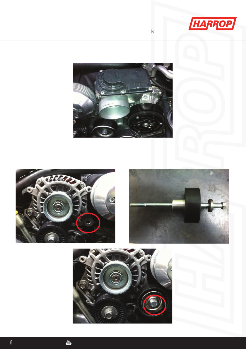
9. Idler and belt installation
9.a. Remove the bolt from the alternator as per image below and install the spacer, idler pulley,
washer and new bolt as shown (torque to 25Nm).
8.c
9.a 9.a
9.a
HARROPPERFORMANCE HARROPTV W: HARROP.COM.AU P: 1300 HARROP E: SALES@HARROP.COM.AU
15
HARROPPERFORMANCE HARROPTV W: HARROP.COM.AU P: 1300 HARROP E: SALES@HARROP.COM.AU
HARROPPERFORMANCE HARROPTV W: HARROP.COM.AU P: 1300 HARROP E: SALES@HARROP.COM.AU
TVS1320 INSTALLATION GUIDE
QUICK START GUIDE FOR EXPERIENCED AUTOMOTIVE TECHNICIANS
ENGINEERING PERFORMANCE SINCE 1955
10.c 10.d & e
HARROPPERFORMANCE HARROPTV W: HARROP.COM.AU P: 1300 HARROP E: SALES@HARROP.COM.AU
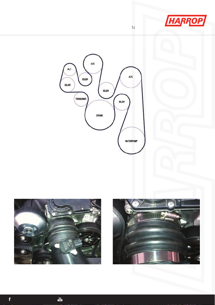
9.b. Using a 14mm socket and bar on the belt tensioner install the supplied belt in the route as
shown.
10. Air box installation
10.a. Install the lter into the standard front half air box.
10.b. Install the supplied clean air side air box and clip into position.
10.c. Install MAF sensor to the inlet tube as shown.
10.d. Install the rubber boot.
10.e. Install hose clamps as shown (it is easiest to fully unwind the hose clamps and install them
after installing the boot).
16

HARROPPERFORMANCE HARROPTV W: HARROP.COM.AU P: 1300 HARROP E: SALES@HARROP.COM.AU
HARROPPERFORMANCE HARROPTV W: HARROP.COM.AU P: 1300 HARROP E: SALES@HARROP.COM.AU
TVS1320 INSTALLATION GUIDE
QUICK START GUIDE FOR EXPERIENCED AUTOMOTIVE TECHNICIANS
ENGINEERING PERFORMANCE SINCE 1955
10.f. Connect the PCV breather line to the air box tting as shown.
10.g. Connect the Throttle and MAF loom and zip tie and secure the throttle / MAF loom.
7.c 10.g
11. Intercooler system installation
11.a. Working from the engine bay connect 4
intercooler lines (2 sets, each hose is a dierent
moulding) to the manifold using the 25mm
cobra clamps and route the lines from the
manifold down to the cavity behind the RH
headlight. Install the 2 hose separator’s in the
positions shown below (separator closest to the
fuse box has a clip over the alternator loom).
11.a
HARROPPERFORMANCE HARROPTV W: HARROP.COM.AU P: 1300 HARROP E: SALES@HARROP.COM.AU
17

HARROPPERFORMANCE HARROPTV W: HARROP.COM.AU P: 1300 HARROP E: SALES@HARROP.COM.AU
HARROPPERFORMANCE HARROPTV W: HARROP.COM.AU P: 1300 HARROP E: SALES@HARROP.COM.AU
TVS1320 INSTALLATION GUIDE
QUICK START GUIDE FOR EXPERIENCED AUTOMOTIVE TECHNICIANS
ENGINEERING PERFORMANCE SINCE 1955
11.b. Working from under the vehicle remove the 2 plastic under trays.
11.c. Remove the RH plastic side cover and cut a hole using the dimensions below to allow for
the intercooler hose to run through it and re install.
11.d. Remove the 4 mounting bolts for the A/C condenser.
11.e. Install the intercooler heat exchanger as show and re install the 4 mounting bolts.
11.c
30mm
150mm
DIAMETER 32mm
HARROPPERFORMANCE HARROPTV W: HARROP.COM.AU P: 1300 HARROP E: SALES@HARROP.COM.AU 18
18
HARROPPERFORMANCE HARROPTV W: HARROP.COM.AU P: 1300 HARROP E: SALES@HARROP.COM.AU
HARROPPERFORMANCE HARROPTV W: HARROP.COM.AU P: 1300 HARROP E: SALES@HARROP.COM.AU
TVS1320 INSTALLATION GUIDE
QUICK START GUIDE FOR EXPERIENCED AUTOMOTIVE TECHNICIANS
ENGINEERING PERFORMANCE SINCE 1955
HARROPPERFORMANCE HARROPTV W: HARROP.COM.AU P: 1300 HARROP E: SALES@HARROP.COM.AU 18
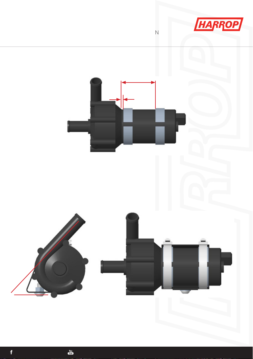
11.f. Assemble the foam onto the pump, the rst strip is placed about 3mm from the pump mo-
tor edge and the second about 60mm.
11.g. Assemble bracket to pump using the hose clamps supplied. Ensure the angle is about 45o
to bracket mounting face.
60mm
3mm
45o
19
Table of contents
Other Harrop Batteries Charger manuals


