Harsper HL-400B User manual

REPORTNO:HCT-F04-0905 FCCID:O5XHL-400B DATE:SEPTEMBER10,2004
HYUNDAI CALIBRATION & CERTIFICATION TECHNOLOGIES CO., LTD.
SAN 136-1, AMI-RI , BUBAL-EUP, ICHEON-SI,KYOUNKI-DO, 467-701,KOREA
TEL : +82 31 639 8518 FAX : +82 31 639 8525 www.hctec.co.kr
ATTACHMENT E.
- User’s Manual (2)

Contents
1
OWNER'S MANUAL
Foreword
Caution ...................................................................................................................................... 3
Important Safety Information .................................................................................................. 5
Overviewing your the Monitor
Viewing the Control Panel ...................................................................................................... 9
Viewing the Connecting Panel .......................................................................................................... 10
Viewing the Remote Control
- Key Description .............................................................................................................................. 12
- PIP(Picture In Picture) Keys ............................................................................................................ 13
- Loading the Batteries ...................................................................................................................... 15
Installation
Table Stand Installation .......................................................................................................... 16
Speaker Installation ................................................................................................................ 17
Connecting the Cable/Devices
Connecting the TV Cable ........................................................................................................ 18
Connecting the VCR ................................................................................................................ 19
Connecting the DVD ................................................................................................................ 20
Connecting the Set Top Box .................................................................................................... 21
Connecting the PC (D-Sub & DVI) .......................................................................................... 22
- Displayable the Monitor Specification.................................................................................... 23
Setting the Channel
Basic Operation ........................................................................................................................ 24
OSD Menu Structure ................................................................................................................ 25
Choosing the Channel Type .................................................................................................... 26
Storing the Channel Automatically ........................................................................................ 26
Fine Tuning the Channel Reception........................................................................................ 27
Setting the Favorite Channel .................................................................................................. 28

Important Safety Information
6OWNER'S MANUAL
Provide ventilation for the Monitor. The unit is designed
with slots in the cabinet for ventilation to protect it from
overheating. Do not block these openings with any object,
and do not place the Monitor on a bed, sofa, rug or other
similar surface. Do not place it near a radiator or heat
register. If you place the Monitor on a rack or bookcase,
ensure that there is adequate ventilation and that you've
followed the manufacturer's instructions for mounting.
Use only the accessory cord designed for this product
to prevent shock. The power supply voltage rating of
this product is AC100-240V, the power cord attached
conforms to the following power supply voltage. Use
only the power cord designated by our dealer to ensure
Safety and EMC.
When it is used by other power supply voltage, power
cable must be changed. Consult your product dealer.
Use only a grounded or polarized outlet. For your safety,
this Monitor is equipped with a polarized alternating
current line plug having one blade wider than the other.
This plug will fit into the power outlet only one way. If you
are unable to insert the plug fully into the outlet, try
reversing the plug. If the plug still does not fit, contact
your electrician to replace your outlet.
Avoid overhead power lines. An outside antenna
system should not be placed in the vicinity of
overhead power lines or other electric light or power
circuits or where it can fall into such power lines or
circuits. When installing an outside antenna system,
be extremely careful to keep from touching the
power lines or circuits. Contact with such lines can
be fatal.
Unplug the Monitor from the wall outlet and disconnect
the antenna or cable system during a lightning storm
or when left unattended and unused for long periods
of time. This will prevent damage to the unit due to
lightning and power-line surges.
Protect the power cord. Power supply cords should be
routed so that they won't be walked on or pinched by
objects placed on or against them. Pay particular attention
to cords at plugs, convenience receptacles, and the point
where they exit from the unit.

13
OWNER'S MANUAL
MTS
Choose the MTS (Stereo) mode. Each time it is
pressed, different mode is selected.
Mono ➔ Stereo ➔ SAP
• You can select only available modes depending on
the source.
CH INFO
Display the current information about time, screen
form, source and MTS mode.
PICTURE
There are 4 picture modes.
Standard ➔ Vivid ➔ Mild ➔ User
STILL
Temporarily freeze the screen and restore it.
SOUND
Choose the sound equalizer settings.
Standard ➔ Movie ➔ Music ➔ News ➔ User
SLEEP
Set the preset time interval for automatic turn-off.
OFF ➔ 10 ➔ 20 ➔ 30 ➔ 60 ➔ 90 ➔ 120 ➔ 150 ➔
180
TIME
Display the current time on the screen.
Digest
Display 15 TV programs at the same time.
CH ADD
Add the current channel to memory.
CH ERASE
Erase the current channel from memory.
CLOSE CAPTION
Set the close caption.
OFF ➔ Close Caption1 ➔ Close Caption2 ➔ Text1
➔ Text2
V-CHIP
Get into V-Chip menu.
1
2
3
4
5
6
7
8
9
12
11
10
PIP (Picture In Picture) Keys
MODE (On / Off)
Activate PIP function and change the PIP
window size and PIP mode.
Small ➔ Large ➔ Twin (Half) ➔ OFF
SOURCE
Change the PIP window source.
SWAP
Swap the main screen and the PIP window.
MOVE
Move the position of the PIP window.
2
6
10
4
3
7
1
5
9
8
12
11
16
15
13
14
13
14
15
16
Viewing the Remote Control

Viewing the Remote Control
14 OWNER'S MANUAL
Source key : Change the source of the PIP window. The available sources are shown as below.
Move key : Move the position of PIP window.
Swap key : Swap the sources of the main screen and
PIP window.
Left Up
Right Up (Start)
Left Down Right Down
MODE KEY : Change the PIP window mode.
OFF ➔ SMALL ➔ LARGE ➔ TWIN
SMALL LARGE TWIN
TV
AV 1
AV 2
S-Video/AV 3
Component1
Component2
PC
DVI
–
–
–
–
–
–
–
–
–
–
–
–
–
–
–
–
–
–
PIP Main TV AV 1
–
AV 2
S-Video/AV 3
Component1 Component2 PC DVI
15
OWNER'S MANUAL
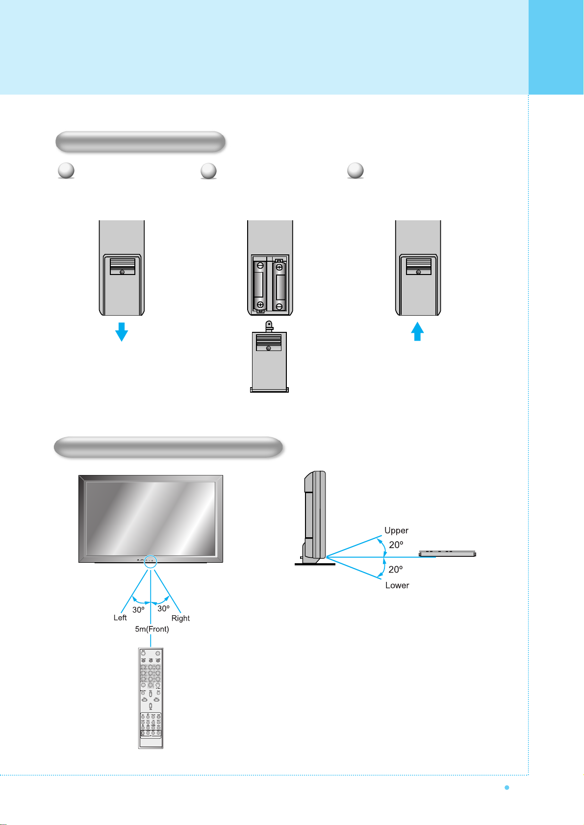
Close the cover until it clicks.Load two AAA batteries, taking
care that the + and - ends face
the correct direction.
Press on the cover and slide
in the direction of the arrow.
123
Loading the Batteries
Reception Range of Remote Control
Viewing the Remote Control

Installation
16 OWNER'S MANUAL
< The Monitor can be installed on the desk as shown above. >
• Table Stand mount minimum allowable clearances for adequate ventilation.
Table Stand Installation (Optional)
1.18 inch
(3Cm)
2.36 inch
(5.99Cm)
4 inch
(10.16Cm)
4 inch(10.16Cm)
4 inch
(10.16Cm)
Installation

17
OWNER'S MANUAL
• Be sure monitor power is turned off before making any connections.
Place the speakers in the position you want. Install the speaker wires on the monitor and speaker. Be sure to connect
the positive "+" wire to the "+" input and the negative "-" wire to the "-" input. Connect left monitor input to left speaker and
right monitor input to right speaker. Any extra speaker wire length remaining can be bunched into the wire holders
provided.
(Caution: Once installed, the speaker wire holders lock into position and can't be removed.)
• Always lift the monitor itself (not the speakers) when handling or moving the monitor after speakers have been
installed.
Speaker Installation (Optional)
4-Iron Plates
(Mount speakers to monitor)
8-4 x 16 Long Bolts
(Attach iron plates to speakers)
8-4 x 8 Short Bolts
(Attach iron plates to monitor)
2-Speaker Wires
Speaker Accessories
Installation

Connecting the TV Cable
18 OWNER'S MANUAL
1
2
3
4
Connecting the TV Cable
Connect the TV antenna cable to the TV input jack. Press INPUT button on the remote control and
select TV on OSD.
Use CH+, CH- button or numeric button to change TV channel for your channel selection.
Press Pre.CH button on the remote control to tune the previous channel.
Also, you can tune to cable service provided channels using the cable box. For further information
regarding cable TV service, contact cable TV service provider(s).

19
OWNER'S MANUAL
Press INPUT button on the remote control and select Video Sources.
Insert a video tape into the VCR and press the PLAY button on the VCR.
With S-Video
Connect a S-Video cable to the S-Video jacks of the VCR and the Monitor.
Connect L (White), R (Red) sound cable (composite) to the sound jacks of the VCR and the Monitor.
With AV input
Connect a composite cable to the AV video jacks of the VCR and the Monitor.
Connect L (White), R (Red) sound cable (composite) to the sound jacks of the VCR and the Monitor.
Connecting the VCR
1
2
Watching VCR
•To avoid picture noise (interference), leave an adequate distance(over 3m) between the VCR and monitor.
• When connecting the Monitor with external equipment, match the colour of connecting ports ( e.g. Video -yellow,
Audio(L) - white, Audio(R) - red).
•If you have a mono VCR, connect the audio cable from the VCR to the AUDIO(L/MONO) input of the Monitor.
• If you connect an S-VHS VCR to the S-VIDEO input socket, you can get a better picture quality than normal video
input (AV).
Connecting the VCR

Connecting the DVD
20 OWNER'S MANUAL
Turn on the DVD player.
Press INPUT button on the remote control of the
Monitor and select Component1 or Component2.
• Connect the three separate component video cables to the DVD player's Y, Pb and Pr jacks and to the
Component jacks on the Monitor.
• Connect the audio cable to the DVD player's audio L (White) and R (Red) jacks and to the L and R audio
jacks beside the Component jacks on the Monitor.
Connecting the DVD
1
2
How to use
Component Input ports
You can get better picture quality if you connect
DVD player with component input sockets as below.
Video output ports of
DVD player
Y
Y
Y
Y
Pb
B-Y
Db
PB
Pr
R-Y
Cr
PR
YPBPR
480i / 60Hz
480p / 60Hz
576i / 50Hz
576p / 50Hz
720p / 50Hz
720p / 60Hz
1080i / 50Hz
1080i / 60Hz
Supported Signals for Component ports
Component1 Component2
Component ports of
the Monitor
•Normal DVD source is based on 480i, which should be through normal YPbPr of Component signal.
•Component, PC, DVI ports can be displayed only 1 signal among them. If one of them is being displayed, other ports
are unavailable.

21
OWNER'S MANUAL
Turn on the Set Top Box.
Press INPUT button on the remote control
of the Monitor and select Component1,
Component2, PC or DVI.
Connect Set Top Box video inputs to AV, COMPONENT, PC or DVI jacks on the Monitor.
Audio inputs to Audio sockets beside the L(White) and R(Red) audio jacks which you connect video inputs.
How to connect
1
2
How to use
How to connect
With Component
Connect a three separate component cables to the component jacks of the STB and the Monitor.
Connect L (White)and R (Red) sound cables (composite) to the sound jacks of the STB and the Monitor.
With RGB(D-Sub) or DVI
Connect a D-Sub or DVI cable to the AV video jacks of the STB and the Monitor.
Connect L (White)and R (Red) sound cables (composite) to the sound jacks of the STB and the Monitor.
•Component, PC and DVI ports can be displayed only 1 signal among them. If one of them is being displayed, other
sockets are unavailable.
Supported Signals
480i/60Hz
480p/60Hz
576i/50Hz
576p/50Hz
720p/50Hz
720p/60Hz
1080i/50Hz
1080i/60Hz
–
–
–
–
Component1 Component2 PC DVI
Connecting the Set Top Box

Connecting the PC (D-Sub & DVI)
22 OWNER'S MANUAL
Pin Configuration
15Pin Signal Cable (based on protruded pin)
To watch the PC screen
Turn on the Monitor and press INPUT button
to select the PC MODE.
Turn on the PC and check for the
PC requirements.
Adjust the PC screen in Geometry menu.
1
2
3
1
2
3
4
5
6
7
8
9
10
11
12
13
14
15
Red (R)
Green (G)
Blue (B)
Grounding
Grounding (DDC)
Red (R) Grounding
Green (G) Grounding
Blue (B) Grounding
Reserved
Sync Grounding
Grounding
Data (DDC)
Horizontal sync.
Vertical sync.
Clock (DDC)
Pin No. Description
Connecting a PC to the Monitor
• There are two connectors to connect the Monitor and PC: D-Sub and DVI.
• D-Sub
Connect a PC (15pin) video cable between the Video Output port on the PC and the PC port on the Monitor.
• DVI
Connect a DVI-D cable between the DVI Output
port on the PC and the DVI port on the Monitor.
23
OWNER'S MANUAL
31.468
37.861
31.469
37.927
31.469
35.000
37.861
37.500
43.269
45.913
53.011
64.062
35.156
37.879
48.077
46.875
53.674
56.000
64.016
49.725
31.468
48.363
56.476
60.023
47.700
64.000
70.09
85.08
70.08
85.03
59.94
66.66
72.80
75.00
85.00
90.03
100.04
120.000
56.25
60.31
72.18
75.00
85.06
90.00
100.00
74.55
60.05
60.00
70.06
75.02
60.00
60.00
Resolution Horizontal Frequency (KHz) Vertical Frequency (Hz)
•Synchronization input form : separate
•The Monitor recognizes 640x480@60Hz signal as
480p DTV signal. So the signal is expanded,
please try other signals like 640x480@75Hz.
•The Monitor operates abnormally if a non-standard
video format is selected.
•1280 X 768 : 40" Native Resolution Horizontal
Polarity is Positive(+) Vertical Polarity is Negative(-)
•Depending on the manufacturer, your PC screen might
appear differently (and depending on your particular
version of Windows).
Check your PC instruction book for information about
connecting your PC to a the Monitor.
• The Monitor may operate abnormally if a non-standard
video signal.
• "Out of range" message box will appear when an
over-spec video signal is input. Change the video settings
of PC when the message is displayed.
• The PC signal is supported by DVI also.
640 x 350
640 x 400
640 x 480
800 x 600
832 x 624
852 x 480
1024 x 768
1280 x 768
1280 x 1024
Displayable Monitor Specification

Basic Operation
24 OWNER'S MANUAL
Press the Power button on the remote control. The Monitor will turn on and you will be ready to use its features.
You can also use the Power button on the front panel.
Press INPUT button on the remote control. Then you can see the source list menu shown as below.
Connect the signal source (TV antenna) to TV input. Press INPUT button on the remote control
and select TV on the source list.
Use CH+, CH- button or numeric button to change TV channel you want.
Press Pre.CH button on the remote control to watch the previous channel.
Also, you can tune the cable service, provided channels while using the cable box.
For further information regarding cable TV service, contact your TV service provider(s).
Use VOL+/VOL- button on the remote control to adjust the volume level.
Press MUTE button on the remote control when you need to cut the sound temporarily.
1
2
3
4
Select the source to watch with CH+/CH- button on the
remote control and press the Menu/Set button.
Source list menu
Source Change
TV
AV 1
AV 2
S-VIDEO /AV 3
COMPONENT 1
COMPONENT 2
PC
DVI
1
2
3
4
5
6
7
8
Turning the Monitor On/ Off
Select Source
Volume Control
TV Channel Selection

25
OWNER'S MANUAL
• OSD (On Screen Display) allows users to control or adjust various features and settings in
accordance with his/her preferences.
• Press the Menu/Set button on the remote control to see the main OSD menu.
EXAMPLE of OSD Menu
Main Menu
Press Menu/Set button on the remote control to enter the main OSD menu.
First, select Main menu item you need with CH+/CH- key.
To select a main menu items, just press VOL+ or Menu/Set button on the Remote Control.
Sub Menu
Each menu item has its own sub menu items to set.
Sub Menu items
A:If there is no ¥part, the item has an sub menu.
You can enter the sub menu and adjust an item you need.
Select sub-menu item with CH+/CH- button on the remote control and press VOL+ or Menu/Set
button to enter the submenu.
B : If there is a ¥part, you can set the item by selecting ¥. Ex) ¥ON or ¥OFF
Press VOL+ or Menu/Set button to set a ¥part, and adjust it with CH+/CH- key.
1
2
3
Mode
Temperature
Video NR
Film Mode
Screen Format
Standard
Normal
ON
OFF
Wide
Picture
OSD Menu Structure

Setting the Channel
26 OWNER'S MANUAL
Before your television can begin memorizing the available channels, you must specify the type of signal
source that is connected to the TV (i.e., an antenna, a standard cable system, an HRC, or an IRC).
Press Menu/set button to display the main
OSD menu.
Select the TV main menu item.
Press Menu/Set to enter the sub menu.
Select Channel Type and press VOL+ button
to enter the ¥ parts. Then the cursor moves
into the ¥ parts.
Select the channel type with CH+/CH- button
and press BACK button. You can select
AIR, CATV (Cable TV), IRC or HRC.
Press Menu/set button to display the main OSD menu.
Select the TV Main menu.
Press Menu/Set to enter the sub menu.
Select Auto Scan with CH+/CH-
button
and press
Menu/Set
button
on the remote control.
Then the tuning bar will appear and scanning will start.
1
2
3
4
5
•You can enter the TV menu in TV mode only.
(When you watch a TV channel.)
Channel Type
¥CATV
Auto Scan
Fine Tune
CH
¥CATV 5
Channel Type
¥CATV
Auto Scan
Fine Tune
CH
¥CATV 5
1
2
3
4
Auto Scan UHF 16
•Only scanned channels can be stored as Favorite channels.
Channel Type
¥
CATV
Auto Scan
Fine Tune
CH
¥
CATV 5
Channel Type
Auto Scan

27
OWNER'S MANUAL
The Fine Tuning function lets you manually adjust the Monitor's tuner if you have difficulty tuning analog
Channels. Press Menu/set button to display the main OSD menu.
Press Menu/set button to display the main OSD menu.
Select the TV main menu item.
Press Menu/Set to enter the Fine tune sub menu.
Select Fine tune with CH+/CH- button and press
Menu/Set button. Then you can see the adjust bar.
Adjust the fine tune with VOL+ or VOL- button.
Digest
In the Digest function, you can watch 15 programs at the same time. (This function works only in TV mode)
Press the Digest button on the Remote Control.
By pressing the channel number, the selected channel
becomes main window.
You can make off the Digest Function by pressing
Digest button again.
1
2
3
4
5
Fine Tune 30
:Move Menu/Set : EXIT
Channel Type
¥CATV
Auto Scan
Fine Tune
CH
¥CATV 5
1
2
3
Fine Tune
Setting the Channel
7
OWNER'S MANUAL
Ground outdoor antennas. If an outside antenna or cable system is connected to the Monitor, be sure the
antenna or cable system is grounded so as to provide some protection against voltage surges and built-up
static charges. Section 810 of the National Electrical Code, ANSI/NFPA No.70-1984, provides information about
proper grounding of the mast and supporting structure, grounding of the lead-in wire to an antenna discharge
unit, size of grounding conductors, location of antenna discharge unit, connection to grounding electrodes, and
requirements for the grounding electrode.
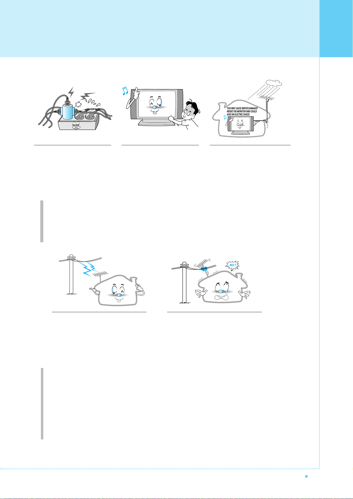
Do not overload the wall outlet or
extension cords. Overloading can
result in fire or electric shock.
Do not insert anything through the
openings in the unit, where they
can touch dangerous voltage points
or damage parts. Never spill liquid
of any kind on the Monitor.
Bend antenna cable between inside
and outside building to prevent rain
from flowing in.
- This may cause water damaged inside
the Monitor and could give an electric
shock.
Do not place an outside antenna in the
vicinity of overhead power lines or other
electric light or power circuits.
- This may cause an electric shock.
There should be enough distance between
an outside antenna and power lines to keep
the former from touching the latter even
when the antenna falls.
- This may cause an electric shock.
Do not attempt to service the Monitor yourself. Refer all servicing to qualified service
personnel. Unplug the unit from the wall outlet and refer servicing to qualified service
personnel under the following conditions:
• when the power-supply cord or plug is damaged
• if liquid has been spilled on the unit or if objects have fallen into the unit
• if the Monitor has been exposed to rain or water
• if the Monitor does not operate normally by following the operating instructions
• if the Monitor has been dropped or the cabinet has been damaged
• when the Monitor exhibits a distinct change in performance
Important Safety Information

Important Safety Information
8OWNER'S MANUAL
When replacement parts are
required, be sure the service
technician uses replacement parts
specified by the manufacturer or
those that have the same
characteristics as the original part.
Unauthorized substitutions may
result in additional damage to the
unit.
Upon completion of any service or
repairs to this the Monitor, ask the
service technician to perform safety
checks to determine that the
Monitor is in a safe operating
condition.
If you make adjustments yourself,
adjust only those controls that are
covered by the operating instructions.
Adjusting other controls may result in
damage and will often require
extensive work by a qualified
technician to restore the Monitor to
normal.
Only use the specified batteries.
- This may cause damage to the
Monitor or could give an electric
shock.
Do not place anything containing
liquid on top of the Monitor.
- This may cause a fire or could give an
electric shock.
In case of smoke or strange smell
from the Monitor, switch it off, unplug
it from the wall outlet and contact
your dealer or service center.
- This may cause a fire or could give an
electric shock.
The viewing distance should be
about 5~7 times as long as diagonal
length of the screen.
- If not, eyes will strain.
When moving the Monitor
assembled with speakers do not
carry holding the speakers.
- This may cause the Monitor to fall,
causing serious injury to a child or
adult, and serious damage to the
Monitor.
Table of contents
Other Harsper Monitor manuals


