Hart and Cooley 7TLC18 User manual

Hart & Cooley, Inc.
Installation Instructions
WARNING: A MAJOR CAUSE OF CHIMNEY-RELATED
FIRES IS FAILURE TO MAINTAIN REQUIRED
CLEARANCES (AIRSPACES) TO COMBUSTIBLE
MATERIALS. IT IS OF UTMOST IMPORTANCE
THAT THIS CHIMNEY BE INSTALLED ONLY IN
ACCORDANCE WITH THESE INSTRUCTIONS.
PLEASE READ AND UNDERSTAND THE REQUIREMENTS BEFORE PROCEEDING
1
All-Fuel Chimney - 5" to 8"
Factory-Built Type HT Insulated Chimney - Tested to UL103
Model TLC
Please read all instructions before beginning your installation.
Failure to install this system in accordance with these instructions will
void the conditions of certification and the manufacturer's warranty.
Keep these instructions in a safe place for future reference.
Type of Appliances
Your Model TLC chimney is intended for venting gas,
liquid, or solid fuel-fired, residential-type appliances and
building heating appliances or as defined in NFPA 211, in
which the maximum continuous flue gas temperatures do
not exceed 1000°F. It has been tested and approved to
withstand temperatures of up to 2100°F for three
10-minute intervals.
Pre-Installation Guidelines
If you choose to have your product installed by others,
we recommend these products be installed by
professionals who are certified by NFI (National Fireplace
Institute) or equivalent.
Your Model TLC chimney and connecting stovepipe
diameter should be sized in accordance with the
appliance manufacturer’s recommendations.
Plan the installation of your appliance and chimney in
such a way that both your chimney and your stovepipe
run as short and straight as possible. By having too long
and/or multiple-bend installations, you can reduce system
draft that can affect the operation and/or performance of
your appliance and/or chimney system. The chimney
should be located within the building in order to avoid
cutting or altering load-bearing members, such as joists,
rafters, studs, etc. If you have to cut or alter an existing
load-bearing member, special reframing methods are
required, which often include doubling of adjacent
members. If such a case arises, contact your local
Building Code Official regarding local regulations and
proper installation methods.
Sections of the Model TLC chimney that pass through
accessible areas of the building, such as through closets,
storage areas, occupied spaces, or any place where the
surface of the chimney could be contacted by persons or
combustible materials, must be enclosed in a chase
to avoid personal contact and damage to the chimney.
The chase may be fabricated using standard building
materials. Drywall mounted on 2" x 4" studs is typically
used in this situation. The space between the outer wall
of the chimney and the enclosure must be at least a
minimum of 2 inches.
MAINTAIN A 2-INCH MINIMUM AIRSPACE
CLEARANCE BETWEEN INSULATED CHIMNEY
SECTIONS AND COMBUSTIBLE MATERIALS.

2
Hart & Cooley, Inc.
Installation Instructions Model TLC All-Fuel Chimney
Contents
Type of Appliances . . . . . . . . . . . . . . . . . . . . . . . . . . . . . . . . . . . . . . . . . . . . . . . . . . . . . . . . . . . . . . .1
Pre-Installation Guidelines . . . . . . . . . . . . . . . . . . . . . . . . . . . . . . . . . . . . . . . . . . . . . . . . . . . . . . 1 & 3
Tools . . . . . . . . . . . . . . . . . . . . . . . . . . . . . . . . . . . . . . . . . . . . . . . . . . . . . . . . . . . . . . . . . . . . . . . . . .4
Framing Details . . . . . . . . . . . . . . . . . . . . . . . . . . . . . . . . . . . . . . . . . . . . . . . . . . . . . . . . . . . . . . . . . .4
Installation Procedures . . . . . . . . . . . . . . . . . . . . . . . . . . . . . . . . . . . . . . . . . . . . . . . . . . . . . . . . . . . .4
Ceiling Support Installation . . . . . . . . . . . . . . . . . . . . . . . . . . . . . . . . . . . . . . . . . . . . . . . . . . . . . . . . . . . . . . . . . . .4
Stovepipe Adapter Installation . . . . . . . . . . . . . . . . . . . . . . . . . . . . . . . . . . . . . . . . . . . . . . . . . . . . . . . . . . . . . . . .5
Attic Insulation Shield Installation . . . . . . . . . . . . . . . . . . . . . . . . . . . . . . . . . . . . . . . . . . . . . . . . . . . . . . . . . . . . . .5
Firestop Radiation Shield Installation . . . . . . . . . . . . . . . . . . . . . . . . . . . . . . . . . . . . . . . . . . . . . . . . . . . . . . . . . . .6
Elbow Installation . . . . . . . . . . . . . . . . . . . . . . . . . . . . . . . . . . . . . . . . . . . . . . . . . . . . . . . . . . . . . . . . . . . . . . . . . .6
Adjustable Wall Support Installation . . . . . . . . . . . . . . . . . . . . . . . . . . . . . . . . . . . . . . . . . . . . . . . . . . . . . . . . . . . .7
Adjustable Intermediate Wall Support Installation . . . . . . . . . . . . . . . . . . . . . . . . . . . . . . . . . . . . . . . . . . . . . . . .12
Cathedral Ceiling Support Installation . . . . . . . . . . . . . . . . . . . . . . . . . . . . . . . . . . . . . . . . . . . . . . . . . . . . . . . . .12
Roof Support Installation . . . . . . . . . . . . . . . . . . . . . . . . . . . . . . . . . . . . . . . . . . . . . . . . . . . . . . . . . . . . . . . . . . .13
Rafter Radiation Shield Installation . . . . . . . . . . . . . . . . . . . . . . . . . . . . . . . . . . . . . . . . . . . . . . . . . . . . . . . . . . .13
Roof Flashing Installation . . . . . . . . . . . . . . . . . . . . . . . . . . . . . . . . . . . . . . . . . . . . . . . . . . . . . . . . . . . . . . . . . . .13
Roof Guy Installation . . . . . . . . . . . . . . . . . . . . . . . . . . . . . . . . . . . . . . . . . . . . . . . . . . . . . . . . . . . . . . . . . . . . . .15
Maintenance and Cleaning of Chimney . . . . . . . . . . . . . . . . . . . . . . . . . . . . . . . . . . . . . . . . . . . . . .15
Creosote and Soot - Formation and Need for Removal . . . . . . . . . . . . . . . . . . . . . . . . . . . . . . . . . . . . . . . . . . . .15
Chimney Fires and What To Do About Them . . . . . . . . . . . . . . . . . . . . . . . . . . . . . . . . . . . . . . . . . . . . . . . . . . . .16
Chart 1 - Offset Chimney Installation . . . . . . . . . . . . . . . . . . . . . . . . . . . . . . . . . . . . . . . . . . . . . . . .17
Chart 2 - Chimney Height Above the Roof . . . . . . . . . . . . . . . . . . . . . . . . . . . . . . . . . . . . . . . . . . . .18
Chart 3 - Connector Pipe Clearance Below Cathedral Support . . . . . . . . . . . . . . . . . . . . . . . . . . . .19
Replacement Parts List . . . . . . . . . . . . . . . . . . . . . . . . . . . . . . . . . . . . . . . . . . . . . . . . . . . . . . . . . . .20
Limited Lifetime Warranty . . . . . . . . . . . . . . . . . . . . . . . . . . . . . . . . . . . . . . . . . . . . . . . . . . . . . . . . .21
Model TLC Chimney & Venting Products . . . . . . . . . . . . . . . . . . . . . . . . . . . . . . . . . . . . . . . . . . . . . . . . . . . . . . .21
Limitations . . . . . . . . . . . . . . . . . . . . . . . . . . . . . . . . . . . . . . . . . . . . . . . . . . . . . . . . . . . . . . . . . . . . . . . . . . . . . . .21
Warranty Coverage . . . . . . . . . . . . . . . . . . . . . . . . . . . . . . . . . . . . . . . . . . . . . . . . . . . . . . . . . . . . . . . . . . . . . . . .21
Claim Procedure . . . . . . . . . . . . . . . . . . . . . . . . . . . . . . . . . . . . . . . . . . . . . . . . . . . . . . . . . . . . . . . . . . . . . . . . . .21
Installation Information Form . . . . . . . . . . . . . . . . . . . . . . . . . . . . . . . . . . . . . . . . . . . . . . . . . . . . . . .24

3
Model TLC All-Fuel Chimney - 5" to 8" Installation Instructions
Hart & Cooley, Inc.
Before beginning the installation, ensure that you obtain
any necessary building permits, and that your installation
will conform with all federal and municipal building code
requirements.
The National Fire Protection Association Standard 211
states: Factory-built chimneys that pass through floors of
buildings requiring the protection of vertical opening shall
be enclosed with approved walls having a fire-resistance
rating of not less than one hour where such chimneys are
located in a building less than four stories in height, and
not less than two hours where such chimneys are located
in a building four or more stories in height.
The chimney must extend not less than 3 feet above the
highest point where it passes through the roof of a
building and not less than 2 feet above any portion of the
building within 10 feet (Figure 1). See Chart 2 - Chimney
Height Above the Roof on page 17 of these instructions.
The use of Locking Bands at all chimney joints is
required for added safety, stability when exposed to high
winds, and as a precaution against accidental unlocking
of lengths when the system is inspected and swept.
The ideal location for your chimney system is within the
building envelope. In cold climates, the use of external
chimneys may result in operational problems, such as
poor draft, excessive condensation of combustion
products, and rapid accumulation of creosote. Under
these circumstances, the installation of the chimney within
the building is strongly recommended.
If the chimney must be installed on an exterior wall, it is
recommended that the chimney be enclosed below the
roof line to protect the chimney from cold outdoor
temperatures; this may help reduce condensation,
creosote formation, and enhance draft. Provide an
access door by the tee cap for chimney inspection and
cleaning. The exterior enclosure may be insulated,
maintaining the required minimum airspace clearance of
2 inches to any part of the chimney. Consult local building
codes for cold-climate application.
Do not install the chimney directly at the outlet of the
appliance. Interconnecting stovepipe is required, unless
the appliance is specifically approved for that type of
installation.
Use only with an appliance listed by a recognized testing
authority, such as Underwriters Laboratories, Inc. or
Intertek Testing Services.
The flue diameter of gas or oil-fired appliance should
comply with the appropriate NFPA or ANSI Installation
Codes, NFPA 54, ANSIZ223.1, and NFPA31.
WARNING: DO NOT PLACE ANY INSULATING MATERIALS
OR RUN ANY ELECTRICAL WIRING WITHIN
THE REQUIRED AIR CLEARANCE SPACE
SURROUNDING THE CHIMNEY.
CONTACT LOCAL BUILDING OR FIRE
OFFICIALS ABOUT RESTRICTIONS AND
INSTALLATION INSPECTION IN YOUR AREA.
WEAR SAFETY GLOVES WHEN HANDLING
SHEET METAL PARTS WITH SHARP EDGES.
YOUR CHIMNEY HAS BEEN TESTED AND LISTED,
USING ALL OF THE SUPPORTS, SHIELDS, ETC.,
DESCRIBED HEREIN. DELETION OR MODIFI-
CATION OF ANY OF THE REQUIRED PARTS OR
MATERIALS MAY SERIOUSLY IMPAIR THE SAFETY
OF YOUR INSTALLATION AND VOID THE CERTIFI-
CATION AND/OR WARRANTY OF THIS CHIMNEY.

4
Hart & Cooley, Inc.
Installation Instructions Model TLC All-Fuel Chimney
Tools
Your Model TLC chimney system is designed for
installation using standard building materials and
procedures. The following tools/equipment may be
required, as well as some others, depending on the
location and structure in which the chimney is to be
installed.
• Safety Gloves • Screwdriver and Pliers
• Safety Goggles • Plumb Line and Level
• Hammer and Nails • Square
• Tin Snips • Keyhole Saw or Power Jigsaw
• Tape Measure • Caulking Gun
Framing Details
Plan your installation carefully. If possible, position the
stove so that the flue outlet is between joists or rafters.
Drop a plumb line to the center of the flue outlet, and mark
this center point on the ceiling. Lay out and frame in all
openings, ensuring the specified 2-inch clearance to
combustibles is maintained. Refer to Table 1 for framing
dimensions, and mark the appropriate cutting lines around
the center point. All openings should be square (all four
sides), plumb, and in perfect alignment with each other
(except for the inside "finished" surface of your wall (Figure 2).
For sloping roofs, ensure that the framing dimension is
measured in the horizontal plane (Figure 3).
Installation Procedures
Ceiling Support (TLCCSB) Installation
To complete a proper ceiling support installation, the
following parts will or may be required.
• Ceiling Support: Required when supporting a chimney
through a flat level ceiling. Also acts as a firestop.
• Attic Insulation Shield: Required where a chimney
passes from a lower living space into an unoccupied
attic space.
• Firestop Radiation Shield: Required where a chimney
passes from a lower living space into an upper living
space or occupied attic space.
• Roof Flashing Assembly (including Storm Collar):
Required when the chimney penetrates a roof.
•Raf
ter Radiation Shield: Required when the chimney is
enclosed immediately below the roof.
• Suitable Lengths of Chimney: The chimney diameter
(ID) should be sized to suit the appliance.
• Elbow Kit: To avoid cutting of joists and clear other
obstructions. Kit includes 2 elbows, 1 offset support,
and 4 locking bands.
• Rain Cap: Deluxe model.
The Model TLC ceiling support will support up to 50 feet
of chimney sections, all of which must be installed above
the support. Figures 4 and 6 show the two most common
types of ceiling support installation. Frame (all four sides)
a level square opening to the dimensions specified in the
Framing Dimensions (Table 1).
Table 1
Chimney
Flue
Diameter
Ceiling
Support*
Wall
(Support)
Thimble*
All
Other
Framing
5" 123/8x 123/814 x 14 11 x 11
6" 123/8x 123/814 x 14 12 x 12
7" 133/8x 133/814 x 14 13 x 13
8" 143/8x 143/814 x 14 14 x 14
Framing Dimensions (in inches)
* When cutting the inside "finished" surface of your wall or
ceiling, cut a "round hole" to the framing dimension.

5
Model TLC All-Fuel Chimney - 5" to 8" Installation Instructions
Hart & Cooley, Inc.
Slide the trim ring onto the ceiling support, and slide the
assembly into the framed opening from below. Ensure
that the finishing ring is flush with the underside of the
ceiling and the assembly is level and plumb. Secure the
ceiling support in place, using at least three 8-penny
(2½") nails through each of the four straps or through the
twelve prepunched holes in the support. You may
substitute, in lieu of nails, twelve #8 x 2" wood screws.
Stovepipe Adapter Installation
The stovepipe adapter is installed by twist-locking it to
the bottom end of the chimney section that enters the
ceiling support. Lower the assembly down into the ceiling
support so that the stovepipe adapter sleeve is protruding
through the support and into the living space.
The crimped end (stub) of the stovepipe adapter is
intended to fit inside the flue pipe from a solid-fuel
appliance, thus preventing condensate drips at the
chimney connection. Install interconnecting flue pipe by
following the appliance manufacturer’s installation
instructions and appropriate building code requirements,
keeping in mind that the flue pipe run should be as short
and straight as practical. Generally, for a wood-burning
appliance installation, an 18-inch minimum clearance to
combustibles must be maintained for a single-wall flue
pipe.
Install additional chimney sections and lock together by
turning clockwise until the two sections lock together
tightly. Install required locking bands. Continue adding
chimney lengths until a height of about 2 feet below the
next ceiling level is achieved.
Attic Insulation Shield Installation
An attic insulation shield must be installed where
the chimney enters an attic space. (It also acts as a
firestop when properly framed.) An attic insulation shield
should keep insulation from coming into contact with the
chimney and will allow a depth of insulation of 10 inches
plus the depth of the ceiling joist. Where height
restrictions will not permit the use of the attic insulation
shield, an enclosure from the attic joist to the roof joist will
be sufficient. All chimney enclosures must maintain the
required minimum airspace clearance of 2 inches to the
chimney. When enclosing the chimney below the roof
line, a rafter radiation shield at the roof level and a
firestop radiation shield at the ceiling level must be
installed.
Table 2 Framing Dimensions
for Attic Insulation Shield
Chimney Flue
Diameter inches
5" 11 x 11
6" 12 x 12
7" 13 x 13
8" 14 x 14

6
Hart & Cooley, Inc.
Installation Instructions Model TLC All-Fuel Chimney
For proper installation, the attic opening must be fully
framed at 2 inches of clearance to the chimney pipe with
framing material of the same dimension as the ceiling
joists, per Table 2 (Framing Dimensions for Attic
Insulation Shield). The tabs on the plate of the attic
insulation shield are inserted in the framed opening
around the chimney. Nail the attic insulation shield base
to the framing dimensions with at least two per side, using
2d 1" spiral nails or 1" x #8 wood screws.
When an attic insulation shield is required above the
ceiling support into an attic as shown in Figure 4, ensure
that the base of the shield is flush with the top of the joist
framing, and nail in place. The telescoping portion of the
attic insulation shield will eliminate the need to trim the
bottom, when installed immediately above the ceiling
support. When fully extended, the attic insulation shield
will provide joist shielding when installed in a two-story
main floor application (Figure 6).
If insulation is blown in and adheres to the chimney pipe,
it must be brushed off to eliminate any possible contact of
this material with the chimney surface.
Firestop Radiation Shield Installation
A firestop radiation shield must be installed where the
chimney passes from one living space to another living
space, as shown in Figure 7. It is designed to provide
proper firestopping between floors and to keep direct
radiation from the chimney away from the joist framing.
Install the firestop radiation shield from below the joist
framing, and nail in place using 1" spiral nails. Ensure no
insulation is within the 2-inch airspace clearance around
the chimney. This includes the airspaces between the
firestop radiation shield and the joist framing.
When the chimney is enclosed in the attic area, a firestop
radiation shield must be installed at the ceiling level. If
the base of the firestop radiation shield does not fit flush
with the ceiling frame, measure the distance that the base
is sitting below the framing, and trim that amount off the
top of the firestop radiation shield before securing into
place.
Elbow Installation
The female end of the elbows are not embossed; this
ensures that proper alignment of the chimney system is
maintained. Locking bands must be installed at all
chimney joints, forming an offset.
Install the insulated offset elbow on the vertical chimney
length, and position the elbow in the required direction.
Fasten the elbow to the chimney length with the supplied
locking band.
One pair of (two) 15° or 30° elbows may be used in an
interior installation to provide an offset, in order to avoid
cutting of joists and to clear other obstructions. Each
elbow support willsupport 15 feet of chimney, and the
maximum length of chimney allowed between elbows is
6 feet.
See Chart 1 - Offset chimney Installation on page 16 in
these instructions for details.

7
Model TLC All-Fuel Chimney - 5" to 8" Installation Instructions
Hart & Cooley, Inc.
Place the required offset chimney length(s) as per the
Offset Chimney Installation chart for appropriate
length(s). Turn it clockwise to lock it in place and fasten
in place with the supplied locking band.
Install the remaining offset elbow to turn the chimney
back to the vertical position and fasten in place with the
supplied locking band.
During installation, provide supplementary support for the
offset section to avoid undue stress on connected elbows.
Install an elbow support just above the highest elbow.
Attach the support band to the chimney with four of the
nuts and bolts, and then install the four stainless steel
sheet metal screws through the prepunched holes. Attach
the support straps to the support band assembly, and nail
the support straps to the framing using 6d 2" nails or
#8 x 1½" wood screws. See Figure 8.
Never install an elbow in a joist area. Chimney sections must
pass vertically through framed joist areas.
Adjustable Wall Support Installation
As previously mentioned, the ideal location for your
chimney system is within the building envelope. A wall
support installation is required when the above-mentioned
location is not possible.
To complete a proper wall support installation, the
following parts will or may be required.
•Wall Support: Intended for a through-the-wall
installation where the chimney has a horizontal
connection.
•Stovepipe Adapter: Transition from chimney to flue pipe.
•Insulated Tee with Insulated Tee Cap: Allowing a
horizontal connection to the chimney.
•Roof Flashing Assembly: Required when the chimney
penetrates a roof or a roof overhang.
•Rafter Radiation Shield: Required when the chimney is
enclosed immediately below the roof.
•Wall Band: Required to provide lateral support to chimney.
•Suitable Lengths of Chimney: The chimney diameter
should be sized to suit the appliance.
•Chimney Length: Appropriate length for connection to
tee branch.
•Wall Thimble: Required to pass though a combustible
wall. It also acts as a firestop.
•Rain Cap: Deluxe model.
8
Hart & Cooley, Inc.
Installation Instructions Model TLC All-Fuel Chimney
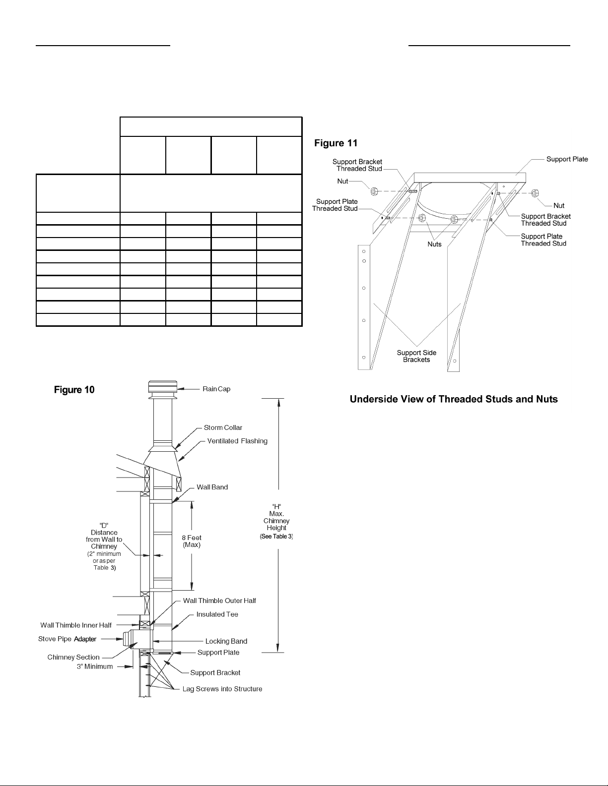
The maximum chimney height above a wall support is
indicated in Table 3 and illustrated in Figure 10, all of
which must be above the support.
See Table 3 for maximum chimney heights based on
chimney diameter and distance from wall.
The wall support will allow for an adjustment of 2" to 6"
from a vertical wall. Threaded studs are factory-installed
on both side brackets and the support plate for fast and
easy assembly. See Figure 11.
Ensure that the wall support brackets are bolted securely
to the wall.
The following steps will assist you in the installation of the
wall thimble and of the wall support. Figure 10 shows a
typical wall support installation through a combustible
wall.
1. Determine the centerline of the horizontal connection
(chimney length through the wall), and frame an
opening to the dimensions for the wall thimble in a
combustible wall. See Table 4 Section A and Figure
12(A).
- Use a stud finder to roughly locate the wall studs.
Mark the outline of the hole and drill a pilot hole in
its center.
- Break out part of the wall covering within the
outline to confirm that the hole will be centered
between studs and that no electrical wires could
be cut by the saw.
2. For a noncombustible wall (concrete block or poured
foundation), cut a hole 3/16" greater in diameter than
the outside diameter of the chimney as per Table 4.
Table 3
5" ID
Chimney
6" ID
Chimney
7" ID
Chimney
8" ID
Chimney
D (inches)
Distance from
Wall to Chimney
2 74635649
2.5 73625548
3 71605347
3.5 69595146
4 66564944
4.5 62534642
5 58504339
5.5 52453835
6 45393430
H (feet)
Maximum
Height
Wall Support Chimney Height Chart
D - Distance from wall to the chimney
H - Height of chimney in feet
See Figure 10 also

3. After framing in your opening to the dimensions
specified to the Framing Tables 1 or 4, install the
outer half (with the unfinished square plate) of the wall
thimble into the outside wall opening. Secure in place
using appropriate fasteners through the prepunched
holes.
4. Install the inner half (with round plate) of the wall
thimble into the inside wall opening, ensuring that the
shield slides over the shield of the outer half. Once in
place and flush against the wall, install the black
finishing trim plate onto the wall surface and fasten in
place with appropriate fasteners through the four
prepunched holes.
Note: To stop cold air infiltration into the dwelling, you
can install the optional Universal Shielding
Insulation (TLCSI) into the wall thimble. See
separate installation instructions packaged
with the Universal Shielding Insulation.
5. Assemble the two side brackets of the Wall Support
(point of angle facing down) to the support plate (flange
up and threaded stud toward the wall) by inserting the
threaded studs into the oblong slots. See Figures 11
and 14. Install the supplied nuts on the threaded
studs until snug. Do not tighten at this time, as
adjustments may be required. Set aside and prepare
the support bracing to secure the side brackets as per
Framing Dimensions Table 4 Section B and Figure
12(B).
Two options are described hereafter for the installation of
the wall support and the insulated tee assembly. Follow
Method A if inserting an assembled insulated chimney
length and insulated tee into the wall thimble prior to the
wall support. Follow Method B if securing the wall
support to the wall prior to the insulated tee and the
insulated chimney length.
9
Model TLC All-Fuel Chimney - 5" to 8" Installation Instructions
Hart & Cooley, Inc.
5" 6" 7" 8"
Section Minimum Round Hole Diameter
for Noncombustible Wall
73/16"8
3/16"9
3/16"10
3/16"
A
Wall Thimble
Minimum Framed Opening
for Combustible Wall
14" x 14" 14" x 14" 14" x 14" 14" x 14"
B
Support Brackets
Minimum Framed Opening
for Bracing
91/4"9
1/4"10
1/4"11
1/4"
Table 4
Chimney Size
Framing Dimensions
Wall Thimble & Support Brackets
Support
Brackets
Figure 14
Threaded Stud
and Nut
located at
rear of
Support Plate
Prepunched
Holes of
Support
Bracket
Support Plate
Flange Up
Stud and
Nut located
to front of
Support
Bracket
Front View of Wall Support Assembly

10
Hart & Cooley, Inc.
Installation Instructions Model TLC All-Fuel Chimney - 5" to 8"
METHOD A
6. Install an appropriate Insulated chimney length such
as a one foot (or longer if required, not to exceed 24
inches) to the horizontal branch of the insulated tee.
Lock securely into the tee branch by twisting
clockwise. A locking band must then be installed to
secure the connection. Make sure the nut and bolt
are facing down to prevent any water from collecting
in the locking band. The tee branch extension must
protrude a minimum of 3" into the room.
7. From outside the building, slide the assembly
(chimney length installed on the tee branch) through
the wall thimble, ensuring the male coupling on the
tee is facing upward. The wall thimble will provide
support until you are ready to install the wall support
assembly.
8. Place the assembled wall support against the wall
(support plate flange up) directly below the insulated
tee. Slide the wall support up to the bottom of the
insulated tee, ensuring that the flange on the top of
the support plate is inserted into the female coupler.
9.
Prior to securing, ensure that the insulated tee
assembly is plumb and level and sitting flush on the
support plate. Secure to the wall through the
prepunched holes located on each side of the wall
support brackets, using (8) #14 x 1½" hex head lag
screws or #10 x 2" wood screws. Make sure they go
into solid bracing as per requirements in Table 4 Section
B and Figure 12(B), below the prepared wall thimble
opening. You can drill 5/32" pilot holes. For concrete
block or poured foundation, use suitable fasteners.
10. Position the support plate the desired distance from
the wall, as per the limits shown in Table 3 and Figure
10. Tighten the 4 nuts onto the threaded studs.
Proceed to Step 14.
METHOD B
11.
Ensure that the wall support is level and secure to the
wall through the prepunched holes located on the
sides of each of the support brackets, using (8)
#14 x 1½" hex head lag screws or #10 x 1½" wood
screws. You can drill 5/32" pilot holes for the lag
screws. Make sure they go into solid bracing as per
requirements. below the prepared wall thimble
opening, See Table 4 Section B and Figure 12 (B). For
concrete block or poured foundation, use suitable fasteners.
12. Place the insulated tee on the support plate, ensuring
that the male coupler of the tee is facing up and the
flange on the top of the support plate slides into the
female coupler. See Figures 15 and 16.
13. From inside the
building, for an
extension of the
insulated tee, slide
an appropriate
insulated chimney
length through the
wall thimble to the
horizontal branch of
the insulated tee.
Lock securely by
twisting clockwise.
A locking band
must then be
installed to secure
the connection.
Make sure the nut
and bolt are facing
down to prevent
any water from
collecting in the locking band. The tee branch must
protrude a minimum of 3" into the room. Use a longer
length if this is not met (not to exceed 24 inches).
Prior to securing, ensure that the insulated tee assembly is
plumb and level and sitting flush on the support plate.
Secure to the wall through the prepunched holes located
on each side of the wall support brackets, using (8) #14 x
11/2" hex head lag screws or #10 x 2" wood screws. Make
sure they go into solid bracing as per requirements in Table 4
Section B and Figure 12(B), below the prepared wall thimble
opening. You can drill 5/32" pilot holes. For concrete
block or poured foundation, use suitable fasteners.
NOTE: For 5" to 7" diameters a choice of two (2) uppermost
mounting holes are available.
Ensure that the wall support is level and secure to the
wall through the prepunched holes located on the
sides of each of the support brackets, using (8)
#14 x 11/2' hex head lag screws or #10 x 11/2" wood
screws. You can drill 5/32" pilot holes for the lag
screws. Make sure they go into solid bracing as per
requirements in Table 4 Section B and Figure 12 (B)
below the prepared Wall Thimble opening. For concrete
block or poured foundation use suitable fasteners. NOTE:
For 5" to 7" diameters a choice of two (2) uppermost
mounting holes are available.
THE CHIMNEY MUST EXTEND AT LEAST
3 INCHES THROUGH THE WALL INTO THE LIVING
SPACE WHERE THE STOVEPIPE CONNECTOR WILL
BE ATTACHED TO THE CHIMNEY BRANCH.
Insulated Tee
Cap
Tee Cap
Bracket
Securing
Screw
Explosion View - Wall Support, Insulated Tee and Tee Cap,
Tee Cap Bracket, and securing Screw
Insulated
Tee
Support Plate
Figure 15
Figure 16
Assembled Wall Support
with Tee Cap Secured in Place

11
Model TLC All-Fuel Chimney - 5" to 8" Installation Instructions
Hart & Cooley, Inc.
14. Use a nonhardening, high-temperature sealant
(500°F) to seal around the horizontal chimney length
where it enters through the exterior of the wall thimble
or the concrete wall.
15. Insert and install the insulated tee cap into the bottom
of the support plate opening. To secure, slide the tee
cap bracket into the slot located at the front and rear
of the support plate. Make sure the tee cap bracket is
beneath the tee cap and the other end exiting through
the slot at the back of the support plate. Secure in
place by threading the securing screw into the nutsert
located on the front of the support plate. See Figures
15, 16 and 17.
Note: If ground clearance does not permit the
installation of the wall support with the support
bracket facing down, it is permissible to invert
these brackets. Inverting the brackets (brackets
mounted above the support plate) can be
accomplished by rotating the support plate so that
the threaded stud faces toward the front and
securing each side with (2) #8 x ¾" bolts (not
supplied) through the oblong slots of the support
side brackets and the support plate as per
Figures 18 and 19. Secure with nuts. In this
position, the range of adjustability is limited to 5"
from the wall (see Table 3). Install the insulated
tee cap as per step 15.
16. Chimney lengths above the insulated tee are simply
stacked on and locked with a 1/8clockwise turn.
17. For lateral stability of the chimney above the wall
support, a wall band must be installed along an
outside wall. Install the first wall band midway up the
first chimney length above the insulated tee and any
additional wall band to be installed at 8-foot intervals
above this point. Secure the wall band bracket to the
wall using 2 6d (2") spiral nails or #8 x 2" wood
screws through the predrilled holes. See Figure 20.
For concrete or brick veneer walls use suitable
masonry fasteners or other anchoring systems.
Figure 18
Support Brackets
Prepunched Holes of
Support Bracket
Slot for
Tee Cap Bracket
Support Plate
with Flange Up
Front View of Wall Support Assembly with
Brackets mounted above the Support Plate

12
Hart & Cooley, Inc.
Installation Instructions Model TLC All-Fuel Chimney - 5" to 8"
18. Fasten the wall band securely around the chimney
with the supplied nut and bolt. Check for clearances
and plumb as you fasten the wall bands to the wall.
Use a level against the chimney sections at each
support stage to keep the assembly plumb.
19. If the chimney penetrates an eave or overhang (soffit)
cut an opening with 2" clearance all around. To find
the exact spot where the chimney will pass through
the eaves, drop a plumb line from the underside of
the eaves to the outer edge of the leveled chimney.
Mark 5 or 6 points to give an outline of the hole.
Remember that the hole will need 2" clearance to the
chimney surface. Install an attic insulation shield if
space permits on the underside of the overhang. If it
is not possible, the overhang area can be enclosed
and a rafter radiation shield installed at the roof level
and a finishing plate on the underside of the soffit. If
the attic is open to the overhang, close off the access
with suitable building materials, ensuring that a 2"
airspace clearance is maintained. From above, install
the roof flashing and storm collar by following the roof
flashing section in these instructions. If the overhang
is not deep enough to allow the chimney to be fully
installed within the overhang, it will be necessary to
cut into it.
Ensure that a 2" airspace clearance all around
the chimney is respected.
Framing and flashing the sides of the opening will be
required. Install a wall band at this level.
Note: Interior chimneys installed with a wall support
must use firestop joist shield in place of wall
bands if extending through floor/ceiling
penetrations and an attic insulation shield when
passing through an unoccupied attic space.
Adjustable Intermediate Wall Support Installation
If the total chimney height exceeds the wall support
limitations, an Adjustable Intermediate Wall Support (TLCIWS)
must be installed. Use of an adjustable intermediate wall support
will support an additional 38 feet of chimney. Slide the
assembled Intermediate wall support over the protruding
length of chimney. Fasten the Intermediate wall support to
the wall, using four ¼" by 2" wood screws through the
prepunched slots in each bracket. Install the draw band
around the protruding chimney length securely against the
support plate. Install four stainless steel sheet metal screws
firmly into the outer casing of the chimney through the
prepunched holes in the draw band. Cover the heads of the
screws with a nonhardening, waterproof caulking.
Cathedral Ceiling Support (TLCCSS) Installation
To complete a proper cathedral ceiling support installation,
the following parts are required.
• Cathedral Ceiling Support: For sloped or angled
ceiling. Also acts as a firestop.
• Roof Flashing Assembly: Required when the chimney
penetrates a roof.
• Suitable Lengths of Chimney: The chimney diameter
should be sized to suit the appliance.
• Rain Cap: Deluxe model.
The Model TLC Cathedral Ceiling Support will support a
total of 38 feet of chimney, of which 15 feet of chimney
can be suspended below the support. All chimney joints
must be secured with locking bands.
After framing in your opening to the dimensions specified
in the Framing Details section, slide the cathedral
support box into joist opening. Once the box is at the
desired level, ensure the box is level, and nail the box to
the framing using four 2" spiral nails or #8 x 1½" wood
screws per side. The excess material sticking above the
roof can either be trimmed off before attaching the box to
the framing, or, after it is installed, the corners can be cut
and the excess material folded down onto the roof deck.
Install the support ring on the chimney length at the
desired position by tightening the draw band bolt and by
screwing four stainless steel sheet metal screws through
the support ring and into the outer casing. Lower the
chimney length down through the opening in the bottom of
the support so that the support ring makes contact with
the bottom of the support box (Figure 21).
Note: The male coupler of each chimney length must be up.

13
Model TLC All-Fuel Chimney - 5" to 8" Installation Instructions
Hart & Cooley, Inc.
The bottom chimney length(s) must protrude into the
living space so that proper clearances are maintained
from the stovepipe connector to the lower side of the
ceiling. For proper clearances, refer to Chart 3 -
Connector Pipe Clearance Below Cathedral Support
on page 18 of these instructions.
Install additional chimney sections and lock together by
turning clockwise until the two sections lock together
tightly. Continue in this manner until the required height
above the roof is achieved.
Chimney sections (15 eet maximum) installed below the
cathedral ceiling support are locked together from below
by turning clockwise until locked together, with
each joint being secured by a locking band. These
lengths can be painted to match the connector pipe by
simply painting with a high-temperature, heat-resistant
paint. To improve adhesion to the Model TLC chimney,
degrease, clean, and prime before painting. Follow the
paint manufacturer•s instructions.
Roof Support Installation
The roof support may be used on a roof, and
any roof pitch. It may be used above an offset to
support the offset or as a supplementary support when the
chimney height exceeds that of the primary support.
The roof support will support a total height of 50 feet of
chimney sections. All chimney sections must be secured
with locking bands.
Attach the support brackets to the support band with the
½" nuts, bolts and lock washers. The lock washer is
placed between the band and support bracket to provide
proper spacing as shown in Figure 22.
Slide the roof support down over the chimney section until its
brackets rest on the roof or floor. Tighten the collar around
the chimney with the nuts and bolts supplied, then secure the
collar by screwing the six supplied sheet metal screws
through the holes in the collar and into the chimney.
Center the chimney in the joist or rafter opening. Ensure
that the 2-inch required airspace clearance is met. Nail or
screw the support to the roof or floor, using the 12 x 3½"
spiral nails supplied or twelve #8 x 1¼" wood screws.
Install additional chimney sections and lock together by
turning clockwise until the two sections lock together tightly.
Continue in this manner until the desired height is achieved.
Note: The male coupler of each chimney length must be up.
Rafter Radiation Shield Installation
A rafter radiation shield must be installed where the
chimney is enclosed immediately below the roof line as
shown in Figure 26. An example of this is when the attic
space of a house is being used as living space
(i.e., bedroom, guestroom, etc.). It must also be installed
when height restrictions will not allow the use of the attic
insulation shield, and the chimney has been enclosed
Attach the support brackets to the shield (through one of
the three prepunched holes), such that once the shield is
installed the shield protects both the upper and lower
parts of the roof joist framing. Rotate the support brackets
to align with the pitch of the roof while allowing the
shield to stay plumb. Secure to the roof.
See Figures 23 and 26.
Roof Flashing Installation
Ensure that you have the proper roof flashing by checking
your roof pitch, using a level and two rulers (Figure 24) or
by using a roof pitch card.
The TLCF6 Roof Flashing is for roof pitches from 0/12 to 6/12.
The TLCF12 Roof Flashing is for roof pitches from 6/12 to 12/12.
The TLCFF is for a flat roof pitch of 0/12 .

14
Hart & Cooley, Inc.
Installation Instructions Model TLC All-Fuel Chimney
Once you have marked and located the area where the
chimney will come through the roof, position and prepare the
roof area. This includes removing shingles, shingle nails, and
cutting roofing material. Be sure to allow for a 2-inch
clearance to the chimney on all four (4) sides. This is done
before extending the chimney above the roof. Do not nail the
flashing to the roof yet, as adjustments may be required.
Note: Slide the top edge (nearest the roof peak) of the
flashing under the roof shingles. At least half of the
flashing should be UNDER the shingles and the
bottom edge OVER the singles to provide a
watershed. Trimming off the shingles may be
necessary around the cone of the flashing for a
better fit. For an existing roof application, lower a
chimney length into the flashing opening, and twist-
lock in place. Ensure that the chimney is level and
plumb before nailing the flashing to the roof.
Nail the flashing to the roof deck (also under the shingles)
along the upper edge and down each side with twelve nails
and neoprene washers, or cover the nails with a suitable
nonhardening, waterproof caulking. Seal the singles to the
plate in the same manner. As a precaution, you may apply a
bead of caulking along all seams of the flashing.
Wrap the storm collar around the chimney above the flashing.
Secure the ends together loosely with the nut and bolt supplied.
Apply a nonhardening, high-temperature silicone caulking
just above the top of the Flashing cone on the chimney
casing. Slide the collar down the chimney until it contacts
the flashing and the caulking. Tighten the nut and bolt,
and apply additional caulking above the storm collar as
required. After the installation, check to ensure that the
ventilation slots are not obstructed. See Figure 26.
On metal or steep roofs, it is recommended that a
chimney cricket fabricated from heavy sheet metal be
installed. This will protect the chimney and the flashing by
routing the snow load and ice around the chimney. This
is not a supplied item. Contact a sheet metal fabrication
shop in your area for your custom chimney cricket.
Warning: Do not block the ventilation slots on the
flashing.
The flashing and storm collar may be painted to match the
roof shingles. This will extend its life and improve the
appearance. The chimney may be painted also with a
HEAT-RESISTANT paint. To improve adhesion to the
Model TLC chimney, degrease, clean, and prime before
painting. Follow the paint manufacturer’s instructions.
Continue adding chimney lengths until the proper height is
achieved. See Figure 1. Install locking bands at all
chimney joints. Install the rain cap, and lock it in place by
turning clockwise until tight.

15
Model TLC All-Fuel Chimney - 5" to 8"
Roof Guy (TLCRGK) Installation
The use of the Deluxe Rain Cap serves many functions. It
prevents the entry or rain, snow and debris into the chimney
opening. It minimizes the effect that wind and air turbulence
have on chimney draft and provides an aesthetically pleasing
termination for the chimney.
Place the Deluxe Rain Cap over the installed chimney and
twist in place by turning clockwise until snug.
Deluxe Rain Cap (TLCC) & Spark Arrester (TLCSA)
Installation Instructions
Hart & Cooley, Inc.
The Universal Roof Brace Kit (URBK/JURGK-1) accommodates most models
of chimneys with outer diameters ranging from 7" through 13".
Spark Arrester
Deluxe Rain Cap
Maintenance and Cleaning of Chimney
Creosote and Soot - Formation and Need for Removal
The need for chimney maintenance depends on the kind
of appliance and how it is operated. Gas and oil-burning
appliances need very little chimney maintenance, but
wood-burning appliances may need a great deal more.
How you burn wood in your stove or fireplace directly affects
the formation of creosote. Use more dry kindling and paper
first to warm up the chimney to a temperature between
350°F to 500°F. Burn hot, bright fires, and fire each load
Use a Spark Arrester if you have a shingle roof or live in a
forrested area. This will prevent the escape of sparks and
burning materials from the chimney.
ATTENTION: Sharp edges! Wear safety gloves when
handling spark Arrester!
Roll-up the Spark Arrester and insert into the bottom of the Deluxe
Rain Cap. Spread out the spark Arrester so that it is snug to the
interior and against the 4 brackets. Secure the Spark Arrester to the
brackets with wire (not supplied).
Burning wood and coal produces creosote, soot, and fly ash which
tend to collect in chimney flue and on termination parts causing
reduced flow of gases through the chimney. Check Rain Cap weekly
for excessive accumulation of these normal combustion products and
clean as necessary. If the Spark Arrester becomes clogged with
creosote, it should be cleaned or replaced.
If the chimney extends 5 feet or more above the roof deck,
roof guys are required. The roof guy kit, containing
telescopic legs and a draw band, is suitable for this
application. The draw band must be clamped around the
chimney and the two legs lagged to the roof into the rafters
and not just the roof sheathing. Position the band
approximately two-thirds of the way up the chimney height.
The preferred location for the band is next to a chimney
joint, immediately above or below a locking band.
If the chimney extends 5 feet or more above the roof deck,
roof guys are required. The roof guy kit, containing
telescopic legs and a draw band, is suitable fort this
application. The draw band must be clamped around the
chimney and the two legs lagged to the roof into the rafters
and not just the roof sheathing. Position the band
approximately two-thirds of the way up the chimney height.
The preferred location for the band is next to a chimney
joint, immediately above or below a locking band.
The two telescopic legs should form an angle of about 60°
to give support to the chimney in all directions. Kiip ends
equal distance from the chimney and, same elebation on
the high side of the sloped roof. Seal the roof with a suitable
non hardening, waterproof caulking. After the legs are
attiched to the chimney and band, tighten the clamps on the
legs to fix the position of the telescopic legs (see Fig 27). See
separate installation instructions packaged with the RGK.

16
Model TLC All-Fuel Chimney - 5" to 8" Installation Instructions
Hart & Cooley, Inc.
Maintenance and Cleaning of Chimney
Creosote and Soot - Formation and Need for Removal
The need for chimney maintenance depends on the kind
of appliance and how it is operated. Gas and oil-burning
appliances need very little chimney maintenance, but
wood-burning appliances may need a great deal more.
How you burn wood in your stove or fireplace directly affect
the formation of creosote. Use more dry kindling and paper
first to warm up the chimney to a temperature between
350°F to 500°F. Burn hot, bright fires, and fire each load
hot. It is important to load your appliance properly and to
avoid smoldering fires. Fast, effective start-ups are
important, as is the moisture content of the wood being
burned. If your wood is not completely seasoned, split your
wood into smaller pieces instead of larger ones. Ideally, the
moisture content of your firewood should be between 18%
to 22%. A good investment in assisting you in monitoring
your system is a surface thermometer for single-wall
stovepipe or a probe thermometer for double-wall stovepipe.
When wood is burned slowly, it produces tar and other
organic vapors, which combine with expelled moisture to
form creosote. The creosote vapors condense in a
relatively cool chimney flue of a slow-burning fire. As a
result, creosote residue accumulates on the flue lining.
When ignited, this creosote creates a chimney fire with
extremely high temperatures.
With a new installation, the chimney should be inspected
frequently (every two weeks) to determine the rate of
creosote formation. When familiar with the appliance and
chimney characteristics, the chimney should be inspected at
least once every two months during the heating season to
determine if a creosote or soot build-up has occurred. Check
spark arrestor screens at least every two to four weeks.
If creosote or soot has accumulated, it should be removed
to reduce the risk of a chimney fire. Depending on the
rate of build-up (as little as 1/16") and as you learn what is
going on in the chimney, you can adjust your cleaning
schedule accordingly. Every chimney flue and flue pipe
should be inspected annually and cleaned as often as
necessary to keep the chimney and flue pipe free from
dangerous accumulation of combustible deposits.
Contact a professional certified chimney sweep for
chimney cleaning services and advice if you have any
doubts about your ability to clean your chimney system or
if the task is too large. To visually inspect the chimney
,
remove the rain cap by simply using the twist-lock feature.
This will permit the insertion of a flashlight for inspection
and a properly sized plastic chimney-cleaning brush.
A metal brush may scratch the liner and lead to premature
corrosion. The tee cap (if so equipped) can be removed
by turning counter-clockwise to clean from the bottom.
Be sure to replace the tee cap and rain cap when you are
finished cleaning the chimney
.
To reduce corrosion in the chimney where coal is burned, the
system must be thoroughly cleaned within 48 hours of shutting
down the appliance for the season, and all soot should be
removed from the chimney system. Ensure that only low
sulphur content coal (1% or less), such as anthracite, is burned.
If a chemical cleaner is used to assist in the cleaning of
your Model TLC chimney, make sure it is a product that is
noncorrosive. It does not replace the need for a
mechanical cleaning. The optimal method for cleaning a
chimney is by a mechanical brushing of the chimney in
conjunction with a complete evaluation of the system by a
certified chimney sweep.
6. After a chimney fire, when it is safe to do so, check
internal locations, such as the attic and under the roof,
and keep watching for two or three hours. There may
be delayed smoldering and subsequent ignition, even if
the fire inside the chimney has been controlled.

17
Hart & Cooley, Inc.
Installation Instructions Model TLC All-Fuel Chimney
Chimney Fires and What To Do About Them
Your Model TLC is not intended or designed for use as a
combustion or fire chamber. It is very easy to overfire your
wood-burning appliance with kindling, scrap lumber, brush,
or any fast-burning fuel. This can produce flames and
high temperatures all the way up the chimney, and may
cause chimney damage. The following materials should
not be burned in your wood-burning appliance: pressure-
treated lumber, railroad ties, salt-water driftwood, or
plastic. Burning such materials may lead to severe
corrosion of the appliance and the chimney system.
If you see your appliance or the stovepipe glowing red,
you are risking chimney damage or a fire. The creosote
may be burning inside the chimney. If you see flames
coming out the top, you are either overfiring or there is a
chimney fire.
If the fire in your appliance has gotten out of control, or if
you suspect a chimney fire for any reason, follow these
step
s.
1. Immediately close all dampers and/or air entrance
openings to your appliance. This includes doors on
Franklin-style stoves. Block off fireplace openings.
2. Alert your family to the possible danger
.
3. Inspect your appliance and chimney surroundings for
possible fire. If in doubt, alert your fire department.
4. Do not continue to use your appliance until it and your
chimney have been thoroughly inspected. Overheating
can cause metal parts to expand, buckle and crack. If
you are not certain, have a certified wood technician or
certified chimney sweep disassemble all parts so they
can be inspected and replaced.
5. Do not use salt or water on the fire in your appliance.
Salt is corrosive, and water will cause a dangerous
steam explosion. Y ou might be able to control the fire
by using ashes, sand, or baking soda. Baking soda is
an ingredient used for dry-chemical fire extinguishers.
6. After a chimney fire, when it is safe to do so, check
internal locations, such as the attic and under the roof,
and keep watching for two or three hours. There may
be delayed smoldering and subsequent ignition, even if
the fire inside the chimney has been controlled.
WARNING:
DO NOT USE FUEL MATERIALS CORROSIVE TO
THE CHIMNEY LINER, SUCH AS DRIFTWOOD,
PLASTICS, CHEMICALLY TREATED WOOD, ETC.

18
Model TLC All-Fuel Chimney - 5" to 8" Installation Instructions
Hart & Cooley, Inc.
42---70-------2
45° Elbow Offset Char
Chart 1 - OFFSET CHIMNEY INSTALLATION
These charts have three columns for elbow angle
required to achieve your desired offset. The first
column (Offset) is the horizontal measurement, at the
chimney centerline, of the offset needed to get around
an obstacle. The second column (Height) is the
height of the assembled offset elbow to the top of the
return elbow. Column 3 shows the appropriate
Lengths Required.
1. Determine the distance of the offset required.
2. On the chart, find the predetermined distance
required for the elbow kit under the corresponding
chimney diameter.
3. After finding the offset, follow across the chart to
find the specified height and appropriate chimney
lengths required under their corresponding
diameters.
Notes:
.Model TLC chimneys are limited to offsets not
exceeding 30°. Combining offsets for greater angle is
not permitted.
.Never install an elbow in a joist area. Chimney
sections must pass vertically through framed joists
area.
.Locking bands must be used at all chimney joints.
.Elbow support will support 15 feet of chimney, and the
maximum length of chimney allowed between elbows
is 6 feet.
.All measurements are in inches.
.Offset tolerances ± one inch.
5" 6" 7" 8" 5" 6" 7" 8" 6" 12" 18" 24" 36"
11/211/811/811/49 10 101/4103/8-----
21/823/823/821/2131/2141/415 155/81----
4 4 4 41/8191/8201/2203/421-1---
51/251/251/255/825 261/4261/2263/4--1--
71/27 7 71/8301/232 321/4321/2---1-
83/883/883/883/8361/2363/437 371/41--1-
101/8101/4101/4101/442 435/844 441/8----1
111/4113/8111/2111/2481/4483/8485/8487/81---1
123/413 13 13 54 541/8543/8545/8-1- -1
143/8141/2141/2145/8593/460 601/8603/8--1-1
16 161/8161/8161/8651/2653/466 661/4---11
-173/8173/8173/8-701/2703/4711--11
19 19 19 19 761/4761/4761/2763/4-1-11
20---76-------2
5" 6" 7" 8" 5" 6" 7" 8" 6" 12" 18" 24" 36"
3 23/431/831/210 115/813 141/2-----
51/451/455/86 14 157/8171/4183/81----
9 81/485/89 191/421 223/824-1---
111/4111/4115/812 241/2261/4275/8291/8--1--
141/4141/4145/815 293/4313/8327/8323/8---1-
16 165/817 171/8341/8355/837 381/21--1-
20 201/4205/821 393/4417/8431/4443/4----1
217/8225/823 231/2441/246 471/2491---1
237/8255/826 261/2501/8511/4525/8541/8-1- -1
271/8285/829 291/2551/8563/8573/8593/8--1-1
303/8315/832 32 605/8615/863 641/2---11
-341/8341/235 - 657/8671/4683/41--11
37 371/8371/238 693/871 721/274 -1-11
30° Elbow Offset Chart (inches)
15° Elbow Offset Chart (inches)
Offset Height Lengths Required
Offset Height Lengths Required

19
Hart & Cooley, Inc.
Installation Instructions Model TLC All-Fuel Chimney
Chart 2 - CHIMNEY HEIGHT ABOVE THE ROOF
Requirement #1: The code requires that the chimney must extend at least 3 feet above the highest point of
the roof that it penetrates.
Requirement #2: The chimney must also be 2 feet above any roof, wall, or other obstruction within a
horizontal distance of 10 feet.
The following chart is provided to assist you in determining the minimum chimney height required above the roof.
You may need to add to this height, as nearby buildings, trees, and other parts of the house roof could interfere
with airflow over and around the top of the chimney and affect its performance. If you think a nearby obstacle
could affect draft, you might want to install one or more additional lengths.
1/12 2/12 3/12 4/12 5/12 6/12 7/12 8/12 9/12 10/12 11/12 12/12
10 feet 36* 44 54 64 74 84 94 104 114 124 134 144
9 feet 36* 42 51 60 69 78 87 96 105 114 123 132
8 feet 36* 40 48 56 64 72 80 88 96 104 112 120
7 feet 36* 38 45 52 59 66 73 80 87 94 101 108
6 feet 36* 36 42 48 54 60 66 72 78 84 90 96
5 feet 36* 36* 39 44 49 54 59 64 69 74 79 84
4 feet 36* 36* 36 40 44 48 52 56 60 64 68 72
3 feet 36* 36* 36* 36 39 42 45 48 51 54 57 60
2 feet 36* 36* 36* 36* 36* 36 38 40 42 44 46 48
1 foot 36* 36* 36* 36* 36* 36* 36* 36* 36* 36* 36* 36
Distance
from Peak
Chimney Height Above Roof (inches)
Pitch of Roof
*Defaulted to 36" to meet Requirement #1. Both requirements (#1 and #2) must be met.
If the chimney extends 5 feet or more above the roof, a universal roof guy kit is required.

20
Model TLC All-Fuel Chimney - 5" to 8" Installation Instructions
Hart & Cooley, Inc.
Chart 3 - CONNECTOR PIPE CLEARANCE BELOW CATHEDRAL SUPPORT
1/12 2/12 3/12 4/12 5/12 6/12 7/12 8/12 9/12 10/12 11/12 12/12
"X" measurement
Box flush to ceiling
on lower end 1.5 3 4.5 6 8 9 10.5 12 13.5 15 16.5 18
Box 1" into the room 1 2 3.5 5 7 8 9.5 11 12.5 14 15.5 17
Box 2" into the room 1 1 2.5 4 6 7 8.5 10 11.5 13 14.5 16
Box 3" into the room 1 1 1.5 3 5 6 7.5 9 10.5 12 13.5 15
"X" measurement
Box flush to ceiling
on lower end 1 1 1.5 2 2.5 3 3.5 4 4.5 5 5.5 6
Box1"intotheroom11111.522.533.544.55
Box2"intotheroom1111111.522.533.54
B
ox3"intotheroom111111111.522.53
1Single-Wall Stovepipe requires an 18-inch clearance from any combustible materials.
2Double-Wall Stovepipe requires a 6-inch clearance from any combustible materials.
Connector Pipe Clearance Requirements from Sloped Ceiling
Pitch of Sloped Ceiling
Exposed
Cathedral Support
into Room
Double-Wall Stovepipe 2
"Y" measurement - Insulated Chimney Length into Room (inches)
"Y" measurement - Insulated Chimney Length into Room (inches)
Single-Wall Stovepipe 1
1. Identify the type of connector pipe you will be installing.
Single-wall stovepipe, which requires an 18-inch clearance to combustibles,
or
Double-wall stovepipe, which requires a 6-inch clearance to combustibles.
2. Determine the amount of the exposed cathedral support that will be
projecting into the room, as per the “X” in the diagram to the right.
3. Select the pitch of your sloped ceiling from the chart below.
4. Select the measurement from the chart below, where the pitch of the sloped
ceiling column intersects with the exposed cathedral row selection. This
will determine the measurement of insulated chimney required below the
cathedral support, as per the “Y” in the diagram to the right. The minimum
of insulated chimney below the cathedral support is 1 inch. This minimum
is required for stability of the system.
This manual suits for next models
9
Table of contents
Popular Fan manuals by other brands


Monte Carlo Fan Company
Monte Carlo Fan Company 5MZR54 D Series installation instructions

Cosa
Cosa CX118/56 instruction manual

SilverStone
SilverStone SST-AP1 manual

Casablanca
Casablanca Tribeca Owner's guide and installation manual

Arbonia
Arbonia Sabiana Maestro MTL-ECM Installation, use and maintenance manual

emerio
emerio FAN-107404 instruction manual


