RP LIGHTING 1072-PC User manual

Installation Guide
For Models:
1072-PC
1072LED-PC

SAFETY INFORMATION
REVERSING SWITCH
TROUBLESHOOTING
TOOLS & MATERIALS REQUIRED 2.3
INSTALLING MOUNTING BRACKET 4
DOWNROD/BALL ASSEMBLY 5
HANGING THE FAN MOTOR ASSEMBLY 5
6.7
BLADE INSTALLATION
7
8
12
11
13
9
OPERATING YOUR FAN
ATTACHING SWITCH HOUSING COVER
10
CANOPY ASSEMBLY
MAKING ELECTRICAL CONNECTIONS
INSTALLING THE LIGHT KIT

1
SAFETY INFORMATION
1. To reduce the risk of electric shock, turn the electricity off at main fuse box or circuit breaker
before beginning fan installation or servicing the fan.
2. Read all instructions and safety information carefully before installing your fan and save this
manual.
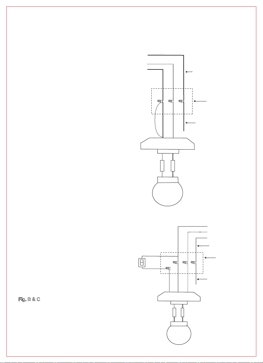
3. All electric connections must be complied with local electrical code and the National Electrical
Code. If you are unfamiliar with electrical wiring, please have a qualified licensed electrician
perform the installation.
4. The fan must be mounted with a minimum of 7 Ft (2.1M) clearance from the trailing edge of the
bales to the floor.
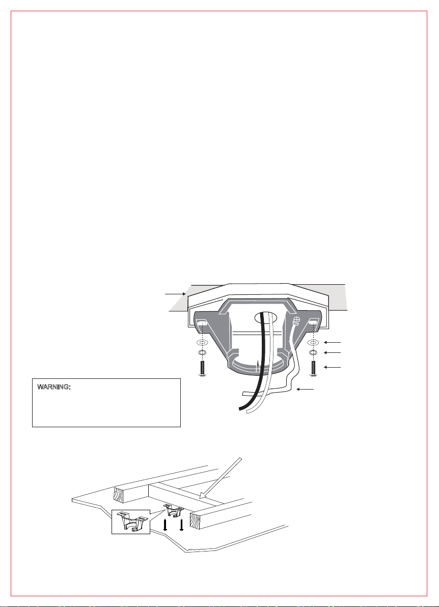
5. The metal outlet box and ceiling support joist must be securely mounted, and capable of reliably
supporting a minimum of 50 lbs ( 23 kgs).
Use only UL - listed outlet boxes marked “Acceptable For Fan Support.”
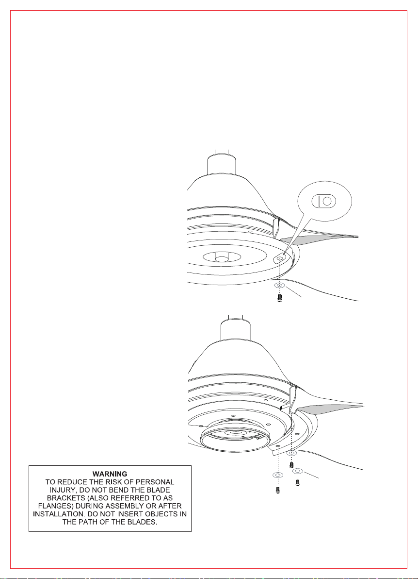
6. To reduce the risk of personal injury, use only approved hanging brackets and screws supplied
with the fan for mounting to the outlet box.
7. After completing installation, check all setscrews and make sure they are firmly secured.
WARNING: To reduce the risk of fire or electric shock, do NOT use this fan with any solid-state speed control
device.
WARNING: To reduce the risk of personal injury, do NOT insert foreign objects in between rotating fan
blades.
CAUTION: To reduce the risk of personal injury, use only set screws provided with the fan for mounting to
the outlet box.
Most outlet boxes commonly used for supporting of the lighting fixture are not acceptable for fan
support and may need to be replaced. Consult a qualified electrician if in doubt.
8. Wooden blades are not intended for storage or installation in spaces that are not
temperature controlled. To avoid issues with blade warping do not store or install ceiling
fans in areas without air conditioning.
9. Do not operate reversing switch while fan blades are in motion. Fan must be turned off
and blades stopped before reversing blade direction.
WARNING: To reduce the risk of personal injury, use only parts provided with fan.
The use of parts other than those provided with fan will void the warranty.

2
TOOLS & MATERIALS REQUIRED
Parts
Mounting bracket 1
Downrod / ball assembly 1
Ceiling canopy 1
Coupling cover 1
Fan motor assembly 1
1
# Quantity
1
2
3
4
5
6
7 Fan blades 3
1 5
6
7
8
2
3
4
Wire nuts 3
#
Q
u
antity
a.
Wood screws 2
b.
Flat washers
2
c.
Hanging bracket screws
2
d.
Spring washers
2
e.
Blade screws and flat washers 10
f.
g.
Pull chain (Wood tassel)
1
h.
Balance kit 1 set
.Ladder
·Wire Strippers
·Phillips Screwdriver
Model#1072-PC
·Pliers
8. Hardware bag included:
Switch housing cover
e.
a.
b. c. d.
f.
g.
h.

3
Parts
Mounting bracket 1
Downrod / ball assembly 1
Ceiling canopy 1
Coupling cover 1
Fan motor assembly 1
LED light kit 1
# Quantity
1
2
3
4
5
6
7 Fan blades 3
1 5
6
7
8
2
3
4
Model#1072LED-PC
Wire nuts 3
#
Q
u
antity
a.
Wood screws 2
b.
Flat washers
2
c.
Hanging bracket screws
2
d.
Spring washers
2
e.
Blade screws and flat washers 10
f.
g.
Pull chain (Wood tassel)
2
h.
Balance kit 1 set
8. Hardware bag included:
e.
a.
b. c. d.
f.
g.
h.

4
INSTALLING MOUNTING BRACKET
Shut the power off at the circuit breaker box before beginning.
Warning: Failure to disconnect power supply prior to installation may result in serious injury.
For safety and best operating results, installation must be undertaken by qualified electrician.
Before installing the fan make sure the outlet box is properly installed to house structure.
Ensure the metal outlet box is securely fastened by at least two points to a structural ceiling
member, a loose box will cause the fan wobble.
Secure mounting bracket to outlet box by tightening
Hanging
bracket screws & spring washers.
If not mount to ceiling outlet box, use wood screws and flat washers and mount securely to
ceiling beam. Note: Do not mount directly to sheet rock or ceiling tiles.
The ceiling fan must be installed in a location with a minimum of 18” spacing from the tip
of the blade to the nearest objects or walls.
Secure the mounting bracket to the ceiling joist or structure that is capable of carrying
a load of at least 40kgs, use two wood screws provided.
BEAM must be able to support up to 40kg.
120V Wires
Hanging bracket screws
UL Listed
Outlet box
Ground wire
Flat Washers
Note: Picture is for representation only and
do not represent the actual bracket.
WARNING:
TO REDUCE THE RISK OF FIRE,
INJURY. MOUNT FAN ONLY ON AN OUTLET
BOX OR SUPPORTING SYSTEM MARKED
“ACCEPTABLE FOR FAN SUPPORT”.
Spring Washers

5
DOWNROD / BALL ASSEMBLY
HANGING THE FAN MOTOR ASSEMBLY
˙Lift the fan assembly onto the mounting bracket.
˙Ensure the notch of the ball joint is positioned on the stopper of the mounting bracket to
prevent the fan from rotating when in operation.
Mounting bracket
Stopper of bracket
Notch of ball joint
˙Locate downrod assembly. Loosen ground
screw on black hanging ball and setscrew to
free lock pin, black hanging ball will slide down.
˙Remove ground screw and green ground wire.
Remove hanging ball from downrod and save all parts.
˙Insert fan wires and safety cable through downrod.
Thread downrod into top of fan motor housing until
holes for downrod pin align with holes in collar.
˙Make sure wires do not get twisted.
Insert downrod pin through coupling and
downrod, secure by tightening security screw.
˙Put canopy in between the downrod and ball,
replace the downrod ball, insert the lock pin
through downrod and tight setscrew against
downrod, tighten ground wire by using ground screw.
Warning:
Failure to tighten setscrew on hanging ball
completely could result in the fan loose and possibly falling.
Lock Pin
Set screws
Coupling cover
White wire
Cross bolt
Black Wire
Downrod
Assembly
Blue wire
Green ground wire
Ball screw
Hanging ball
Canopy
Downrod

6
MAKING ELECTRICAL CONNECTIONS
INPUT VOLT.120V
GREEN GROUND
OUTLET BOX
IN CEILING
GROUND TO
HANGER BRACKET
AND DOWNROD
Connect Black(Hot) fan wire to Black outlet wire,
white (Neutral) fan wire to white outlet wire.
Connect green or bare copper wire from outlet
box to the hanger bracket and downroll ball
green ground wires together. (Fig.A)
If an additional blue lite kit wire is present,
then also connect the blue wire to black wire.
Secure all connections with electrical tape.
Make sure there are no loose strands or
connections.
Follow the steps below to connect the fan
to your household wiring. Use the wire
connecting nuts supplied with your fan.
After completing wiring connections, turn all
splices upward and carefully push into outlet
box.
Separate blue and black wires on one side of
the outlet box, the white and green wires on
the other side.
ELECTRICAL CONNECTIONS
(FOR OPTIONAL WALL CONTROL)
Fig. B & C
illustrate the wiring connections for
optional wall control (The wire color out of wall
control may vary, see wall control’s installation
manual for correct wire connections.)
(Fig.B)
INPUT VOLT.120V
GREEN GROUND
OUTLET BOX
IN CEILING
GROUND TO
HANGER BRACKET
AND DOWNROD
BLK
BLK
BLK
BLUE
BLUE
WH
WH
WH
WH
GRN
FAN
LIGHT
(Fig.A)
Follow this wiring diagram. Fan & Wall control
sold separately, choose wall dimming control
compatible with LED light only.
LIGHT
SWITCH
BLK
BLUE
BLUE
BLK
BLK
WH
WH
FAN
LIGHT
WH
WH
Step 1.
Warning: All wiring must be in accordance with
national and local electrical codes ANSI/NFPA
70. If you are unfamiliar with wiring or in doubt,
consult a qualified electrician.
Step 2.

7
CANOPY ASSEMBLY
˙After completing electrical connections,
cover the mounting bracket with canopy.
Tuck all wire connections neatly back into
ceiling outlet box. Remove two of 4 screws
from the mounting bracket and loosen the
other two screws but not remove.
˙Slide the canopy up to the mounting bracket,
align the locking slots of the ceiling canopy
with two screws in the mounting bracket.
Push the canopy to engage the slots and
immediately tighten the two mounting screws firmly.
Re-install the two screws removed previously
into the slotted holes in canopy and tighten firmly.
Loosen but not remove
NOTE: Only use an optional wall switch
designed for use with ceiling fans.
If you select to control the motor from a wall
switch, remember the wall switch will only turn
your fan ON or OFF. The speed can be adjusted
by pull chain.
If you select to control the light of ceiling fan
from a wall switch, you must pull the light chain
to the “ON” position.
If you select to control the speeds of ceiling fan
from a wall switch, you must set the speed switch
on ceiling fan to HIGH speed and leave it in that
setting.
(Fig.C)
INPUT VOLT.120V
GREEN GROUND
OUTLET BOX
IN CEILING
GROUND TO
HANGER BRACKET
AND DOWNROD
BLK
BLKBLUE
BLK
BLUE
WH
WH
WH
WH
FAN
LIGHT
LIGHT
FAN

8
BLADES INSTALLATION
˙Attach each fan blade to the flywheel using 3 blade screws and washers, locate a slot hole on
the mounting plate and secure the blade screws through the slot hole.
NOTE: Place the fan blade on the flywheel and align the middle hole on the fan blade with
the hole next to a debossed line on the flywheel.
˙Repeat this process to install the other blades to the motor.
CAUTION: Do not install fan blade until the fan is completely installed.
Model#1072-PC
Model#1072LED-PC
Flat washer
Flat washer

9
Model#1072-PC
ATTACHING SWITCH HOUSING COVER
Locate 3 screws on switch housing mounting plate, attach the cover to switch housing
by using these 3 screws and tighten securely.
Switch housing

10
CAUTION: To reduce the risk of electric shock, disconnect the electrical supply circuit
to the fan before installing light kit.
Connect the 4-pin connector from the LED light kit to the 4-pin connector from motor assembly
together carefully. The LED light kit is designed for this specific application on
ceiling fan model#1072LED-PC, secure the light kit to mounting plate by twisting in clockwise
direction then lock in place.
Mounting plate
INSTALLING THE LIGHT KIT

11
Connect the WOOD TASSEL to the pull chain located in switch housing.
Turn on the power and check the operation of your fan.
3-SPEED PULL CHAIN
1 pull = High Speed
2 pulls = Medium Speed
3 pulls = Low Speed
4 pulls = Fan Off
Even if the fan is mounted with a minimum of 7 feet clearance from the trailing edge
of the blades to the floor, be careful to avoid raising your arms or nay object in the path
of the blades.
Connect the two WOOD TASSELS to the pull chains located in light kit ( Model #1072LED-PC ).
One is for the fan, and the other is for the light.
The pull chain switch for the light kit is two positions ON / OFF.
To turn the LIGHT KIT “ON” or “OFF”, pull the chain attached to the light kit.
Note:
OPERATING YOUR FAN

12
Your ceiling fan can operate either summer or winter mode.
SUMMER Mode: The reverse switch shall be in the “left” (SUMMER) position to make the fan rotate in an
anticlockwise direction. The airflow will be directed downwards, for cooling in summer.
WINTER Mode: The reverse switch shall be in the “right” (WINTER) position to make the fan rotate in a
clockwise direction. The airflow will be directed upwards assisting in the circulation of warm air, for energy
conservation in winter.
REVERSING SWITCH
SUMMER WINTER
Reverse Switch

13
TROUBLESHOOTING
Problem Solutions
Fan will not start.
Fan sounds noisy.
Fan wobbles
CARE OF YOUR FAN
Here are some suggestions to help you maintain your fan.
1. Because of the fan's natural movement, some connections may become loose. Check the support
connections, brackets, and blade attachments twice a year. Make sure they are secure. (It is not
necessary to remove fan from ceiling.)
2. Clean your fan periodically to help maintain its new appearance over the years. Use only a soft brush or
lint-free cloth to avoid scratching the finish. The plating is sealed with a lacquer to minimize discoloration
or tarnishing. Do not use water when cleaning. This could damage the motor, or the wood, or possibly
cause an electrical shock.
3. You can apply a light coat of furniture polish to the wood blades for additional protection and enhanced
beauty. Cover small scratches with a light application of shoe polish.
4. There is no need to oil your fan. The motor has permanently lubricated bearings.
WARNING:
Failure to disconnect power supply prior to troubleshooting any wiring issues may result in serious injury.
- Check circuit fuses or breakers.
- Check line wire connections to the fan and switch wire connections in the switch housing.
- Make sure all motor housing screws are snug.
- Make sure the screws that attach the fan blade bracket to the motor hub is tight.
- Make sure wire nut connections are not rubbing against each other or the interior
wall of the switch housing.
- Allow a 24-hour "breaking-in" period. Most noise associated with a new fan
disappear during this time.
- If using an optional light kit, make sure the screws securing the glassware are tight.
Check that light bulb is also secure.
- Some fan motors are sensitive to signals from solid-state variable speed controls.
If you have installed this type of control, choose and install another type of control.
- Make sure the upper canopy is a short distance from the ceiling. It should not
touch the ceiling.
- Check that all blade and blade arm screws are secure.
- Most fan wobbling problems are caused when blade levels are unequal. Check this
level by selecting a point on the ceiling above the tip of one of the blades. Measure
this distance. Rotate the fan until the next blade is positioned for measurement.
Repeat for each blade. The distance deviation should be equal within 1/8".
- Use the enclosed Blade Balancing Kit if the blade wobble is still noticeable.
- If the blade wobble is still noticeable, interchanging two adjacent (side by side)
blades can redistribute the weight and possibly result in smoother operation.

RP-120419
This manual suits for next models
1
Table of contents
Other RP LIGHTING Fan manuals

RP LIGHTING
RP LIGHTING 1076 User manual

RP LIGHTING
RP LIGHTING 1070 User manual

RP LIGHTING
RP LIGHTING 1021-PC User manual

RP LIGHTING
RP LIGHTING 1070W User manual

RP LIGHTING
RP LIGHTING 1073LED-PC User manual

RP LIGHTING
RP LIGHTING 1070W User manual

RP LIGHTING
RP LIGHTING 1060 User manual

RP LIGHTING
RP LIGHTING 1052 User manual

RP LIGHTING
RP LIGHTING 1088 User manual