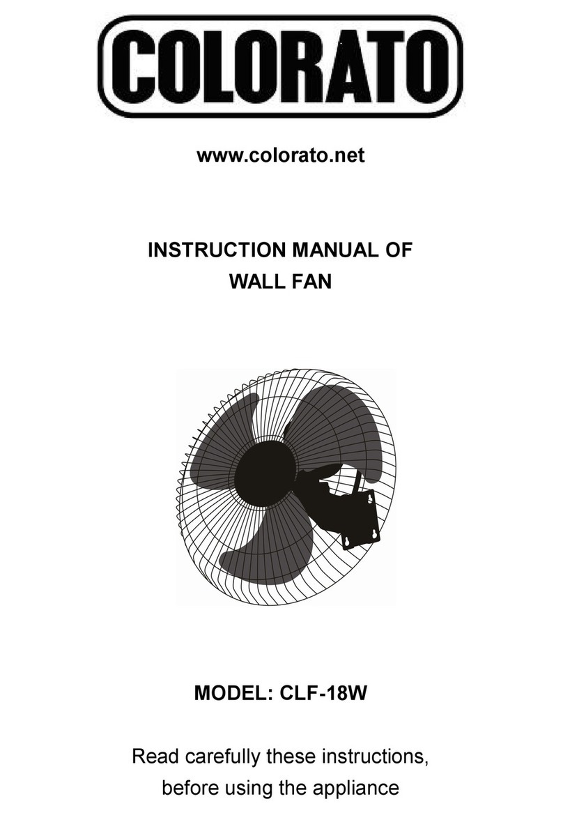
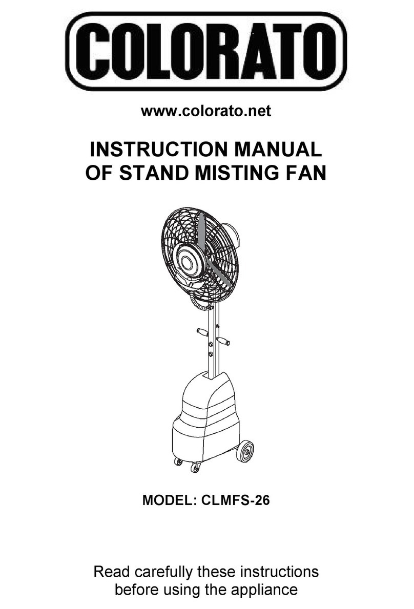
COLORATO CLF-20WRC User manual

www.colorato.net
INSTRUCTION MANUAL OF INDUSTRIAL FAN
MODELS: CLF-20WRC, CLF-26WRC, CLF-26SE

WARNING: WHEN USING ELECTRIC PRODUCTS, BASIC SAFETY
PRECAUTIONS SHOULD ALWAYS BE FOLLOWED TO REDUCE THE RISK OF
FIRE, ELECTRIC SHOCK AND PERSONAL INJURY ETC.
CAUTION:
1. CONSIDER WORK AREA ENVIRONMENT
DO NOT use the fan in damp or wet locations. DO NOT use the fan in presence of flammable
liquids or gases and high temperature. DO NOT restrict air intake. DO NOT use the fan near
window curtains or unstable area.
2. DO NOT ABUSE THE POWER CORD
Never pull the fan from the power cord and never pull the power cord in order to unplug it. Keep
the power cord away from heat, oil and sharp edges.
3. DISCONNECT THE FANS
Disconnect the fan when you are not using it, before maintenance or while assembling parts.
4. INSPECT FOR DAMAGE
Before using the fan check it for damages. Before using it make sure that it will work properly.
Check the alignment or the motor’s connection and if the blades are installed firmly on the
motor. Make sure that the front guard is fixed with the back guard. Inspect the power cord
periodically for damage. Check the power switch by turning the fan on and off while the unit is
connected to the power. If any of the above are broken or is not working properly, you should
take the fan to repair or replace the broken parts.
5. ATTENTION TO THE CHILDREN
The children are not allowed to approach the fan, put their fingers or other objects, like screws,
inside the guards where the air enters or exits, while the fan is working.
6. REPLACEMENT OF THE PARTS
During repair, use only authentic parts that are supplied by the manufacturers, in order to
replace the broken parts. The replacements should be done only by qualified technicians.
MAIN TECHNICAL CHARACTERISTICS
MODELS DIMENSIONS
(mm)
VOLTAGE-
FREQUENCY
(V/Hz)
NOISE
LEVEL
(Db (A))
INPUT
POWER
(W)
AIR VOLUME
(m³/min)
COVER AREA
(m²)
CLF-20WRC
510 220-240/50 65 125 150 20-25
CLF-26WRC
660 220-240/50 69 170 185 30-35
CLF-26SE 660 220-240/50 69 170 185 30-35

ASSEMBLING DIAGRAM
WALL FAN
ASSEMBLING ORDER
STAND FAN
ASSEMBLING ORDER
1. FRONT GUARD
2. BLADE
3. SCREW
4. BOLT
5. SPRING WASHER
6. GASKET
7. BACK GUARD
8. NUT
9. SPRING WASHER
10. GUARD CLIP
11. GUARD CLIPSCREW
12. NUT
13. MOTOR
14. GASKET
15. SCREW
16. WIRING CLIP
17. FIXING COVER
18. BOLT
19. FIXING SCREW
20. SUPPORT
21. STANCHION
22. DECORATING COVER
23. SQUARE BASE
24. GASKET
25. SPRING WASHER
26. BOLT
27. BOLT
28. NUT
29. BOLT
30. BOLT
31. WALL PLATE
32. SUPPORT ARM
33. FIXING SCREW
34. LOWER CONNECTION
35. HOLDER OF THE MOTOR
SUPPORT
35→33→34→32→30→31→29→
28→13→18→15→14→7→6→5→
4→2→3→1→10→11→12→9→8→
17→16
21→23→24→25→26→27→22→19→
20→13→18→15→14→7→6→5→
4→2→3→1→10→11→12→9→8→
17→16
INSTALLATION DIMENSION
SPEC 500mm 600mm 650mm 750mm
ФA Ф564 Ф654 Ф706 Ф824
B~C 1235~1760
D 600 600 600 700

OPERATION
1. Power source:
Check voltage and frequency before use to avoid any problems.
2. Installation plug 220/240V-50Hz:
Always use grounded plug for security and protection.
3. Oscillating-rotation control:
The oscillating structure is shown in the drawing. It can be adjusted in the angle from 0º~90º. When
adjusting screw is moved to the direct axle, the fan will not oscillate. The longer the distance from adjusting
screw to the direct axle is, the larger the oscillating angle will be. Before you change the oscillating angle cut
off the power, then loosen the adjusting screw and turn it to the suitable position to obtain satisfactory angle.
The fan with 450 mm can be also controlled by the swing pole on the back of the motor. When the pole is up
the fan is swinging. When the pole is down the fan is stopping.
4. Change of the wind direction:
If you want to change the direction of the wind, cut off the power, loosen the direction-changing bolt, adjust
the direction of the fan head and then tighten up the bolt. It is not necessary to move the base of the fan.
5. Upward and downward adjustment:
Cut off the power first, hold the head of the fan, loosen the connecting bolt and adjusting bolt, adjust the fan
to satisfactory height position and tighten up the two bolts.
6. Adjustment of the height of the head of the stand type fan.
Loosen the locking bolt, adjust the fan head to ideal position and then tighten up the locking bolt. In order to
avoid the fan head falling down suddenly and any accidents, the fan head must be held when the locking
bolt is being loosened. Cut off the power before adjustment.
7. Installation of the wall fan base:
The bending part of the fan can be installed upward or downward. In both cases, the longer one of the two
locking bolts must perpetrate the small hole at the end of the bending part in order to avoid falling off.
8. Adjustment of air volume:
Turn the switch on the back of the fan head to control the operation of the fan and adjust air volume, “0”
represents “stop”, “1-3”speeds indicate different air volumes.
9. Safe aspiration:
Move the fan only when power is off. Do not block the oscillation of the fan to avoid any problems.
10. Cautions of installation:
For convenient transportation, the supporting pillar of the stand type fan and the base of the wall type fan
are disassembled in packing. Please install the fans according to the drawings of this manual.
MAINTENANCE OF THE FAN
To keep the fan, motor, blades and fan guards clean in a safe way, please follow the steps below:
Α) Unplug the fan and loosen the clips on the fan guards before using dry cloth to keep the fan away from
dust.
Β) Gently wipe the blades to avoid them being out of shape, resulting in disorder of operation.
Γ) Ensure all the parts have been fastened after reassembling.
Δ) Keep fan a trial running for 5 minutes to confirm its normality. Should anything of the fan be found
abnormal after cleaning, please stop it immediately to have it checked and fixed by electricians. Self
dismantlement in such kind of case is dangerous and absolutely forbidden.
Ε) Grease change: After the fan has operated over 2000 hours (or at least5 once a year), the grease in the
gear box and bearing should be changed.
ATTENTION
The symbol on the product means that at the end of its life, the appliance has not to be
considered as a common waste. It is a special waste and has to be demolished in specifies
recovery and disposal areas, as prescribed by the EC Directive 2002/96/EC (WEEE). By disposing
this product correctly, you can avoid negative consequences for the environment and for the
human health, due to the presence of potentially dangerous substances in the product.

INSTRUCTION MANUAL FOR REMOTE CONTROL
BUTTONS AND FUNCTIONS
OFF: Turns the fan off.
ON/SPEED: Turns the fan on and with repeat pressing adjusts the fan’s speed to LOW, MED,
HIGH.
TIME: It controls the work time. Each pressing adds 0,5 h and the max working time is 7,5 h.
MODE: The fan has 3 different work modes: normal, natural και sleeping.
- Normal: The fan works normally
- Natural: Imitates natural wind working. Different speed, different effects.
- Sleeping: This mode is similar to natural, only the power is low and it is ideal for sleeping.
SWING: This mode is only for oscillating fan with synchronous motor. Not for industrial fan.
TIME MODE SWING
OFF ON/SPEE
D
This manual suits for next models
2
Table of contents
Other COLORATO Fan manuals
Popular Fan manuals by other brands

Duco
Duco DucoBox Silent Series installation guide

Maico
Maico Centro-M Installation and operating instructions

Trox Technik
Trox Technik TSD -3-NF Series installation instructions

VES
VES Ecovent EVH Series Operation & maintenance manual

Schako
Schako JK-180MB Technical documentation

Cairox
Cairox KBF-N D Series manual