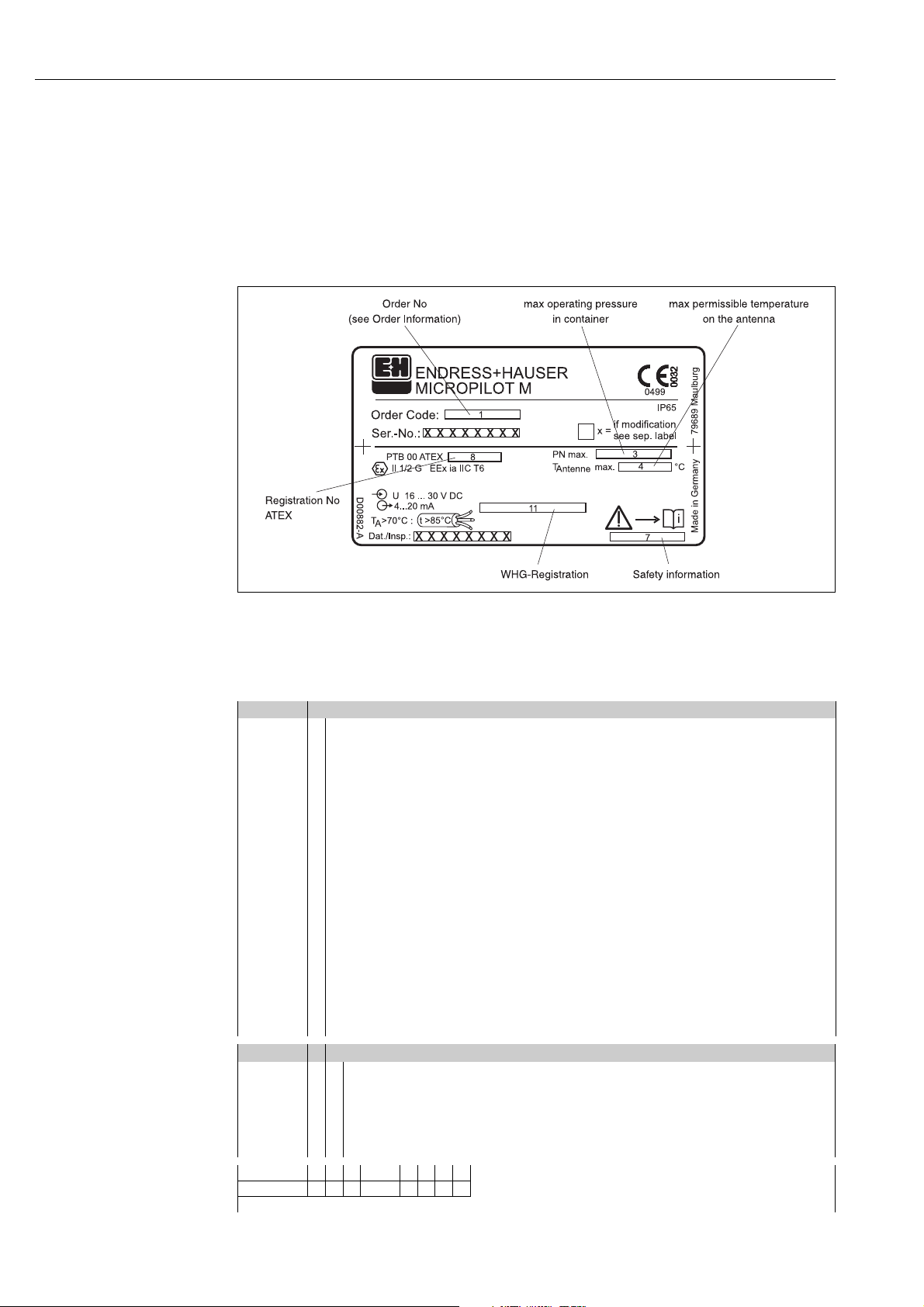
Micropilot M FMR 230 with HART/4...20 mA Identification
Endress + Hauser 7
Ordering structure Micropilot M FMR 230 (continued)
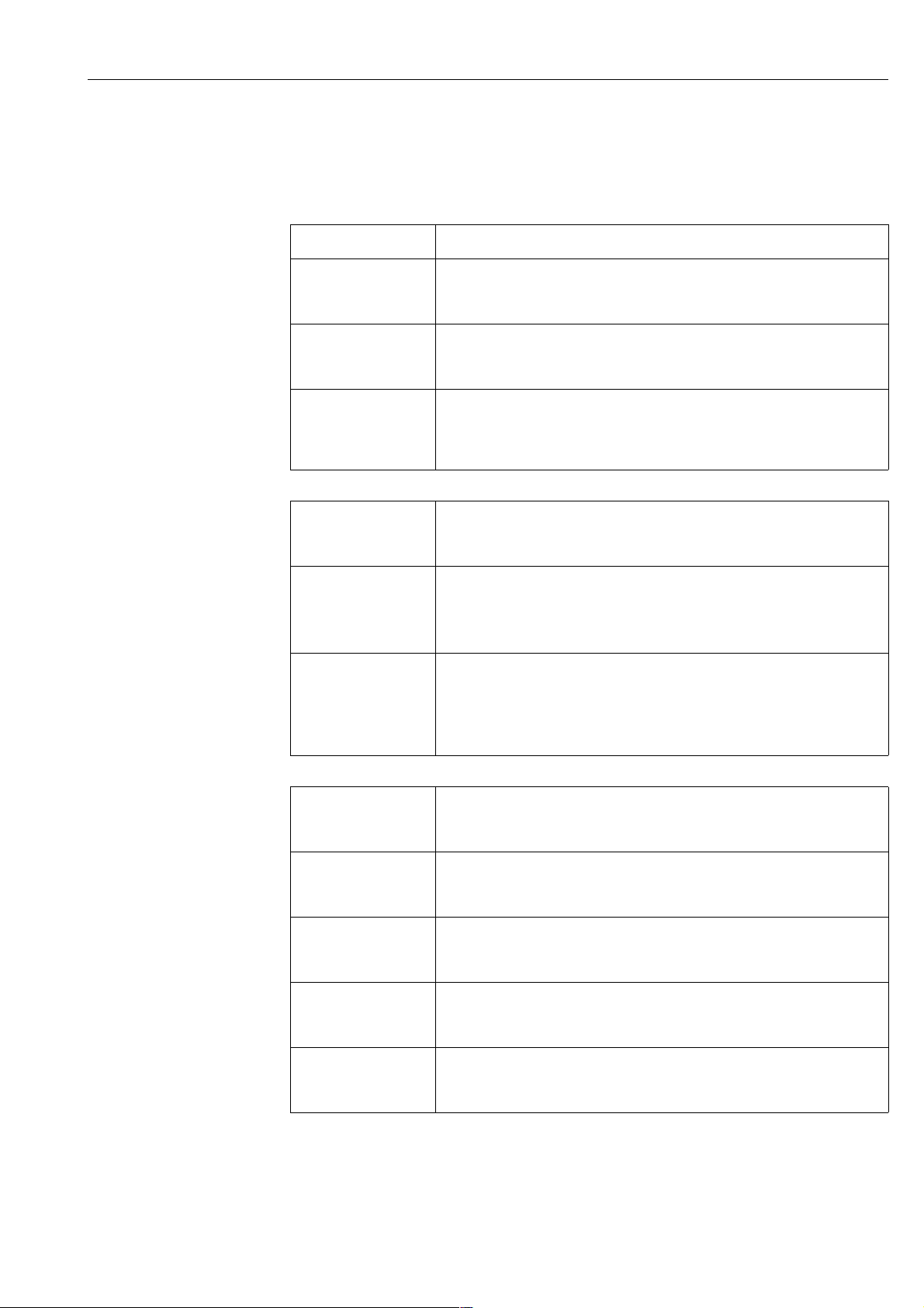
30 Type of antenna, sealing, temperature
Type Sealing Temperature range
V Standard Viton/FKM -20 °C…200 °C / -4 °F…+392 °F
E Standard EPDM -40 °C…150 °C / -40 °F…+302 °F
K Standard Kalrez 0 °C…200 °C / 32 °F…+392 °F
L Extended temperature Graphit -60 °C…280 °C / -76 °F…+536 °F
M High temperature Graphit -60 °C…400 °C / -76 °F…+752 °F
H Enamel antenna PTFE -40 °C…200 °C / -40 °F…+392 °F
Y Special version
40 Process connection, material
Flange Dia/Pressure Standard Material
CMJ DN80 PN16 EN 1092-1, B11) 316L
CNJ DN80 PN40 EN 1092-1, B11) 316L
CQJ DN100 PN16 EN 1092-1, B11) 316L
CQ5 DN100 PN16 EN 1092-11) Alloy C4 >316Ti
CRJ DN100 PN40 EN 1092-1, B11) 316L
CWJ DN150 PN16 EN 1092-1, B11) 316L
CW5 DN150 PN10/16 EN 1092-11) Alloy C4 >316Ti
EWT DN150 PN16 EN 1092-1, B11) enamelled steel
CXJ DN200 PN16 EN 1092-1, B11) 316L
EXT DN200 PN16 EN 1092-1, B11) enamelled steel
C6J DN250 PN16 EN 1092-1, B11) 316L
C65 DN200 PN16 EN 1092-11) Alloy C4 >316Ti
ALJ 3"/150 lbs ANSI B16.5 316/316L
AMJ 3"/300 lbs ANSI B16.5 316/316L
APJ 4"/150 lbs ANSI B16.5 316/316L
AQJ 4"/300 lbs ANSI B16.5 316/316L
AVJ 6"/150 lbs ANSI B16.5 316/316L
AV5 6"/150 lbs ANSI B16.5 Alloy C4 >316Ti
AVT 6"/150 lbs ANSI B16.5 enamelled steel
A3J 8"/150 lbs ANSI B16.5 316/316L
A35 8"/150 lbs ANSI B16.5 Alloy C4 >316Ti
A3T 8"/150 lbs ANSI B16.5 enamelled steel
A5J 10"/150 lbs ANSI B16.5 316/316L
A55 10"/150 lbs ANSI B16.5 Alloy C4 >316Ti
KA2 10 K 80A JIS B2210 316Ti
KH2 10 K 100A JIS B2210 316Ti
KV2 10 K 150A JIS B2210 316Ti
KD2 10 K 200A JIS B2210 316Ti
K52 10 K 250A JIS B2210 316Ti
1) agreeable to DIN 2527
TL2 3" Tri-clamp ISO 2852 316Ti
YY9 Special version
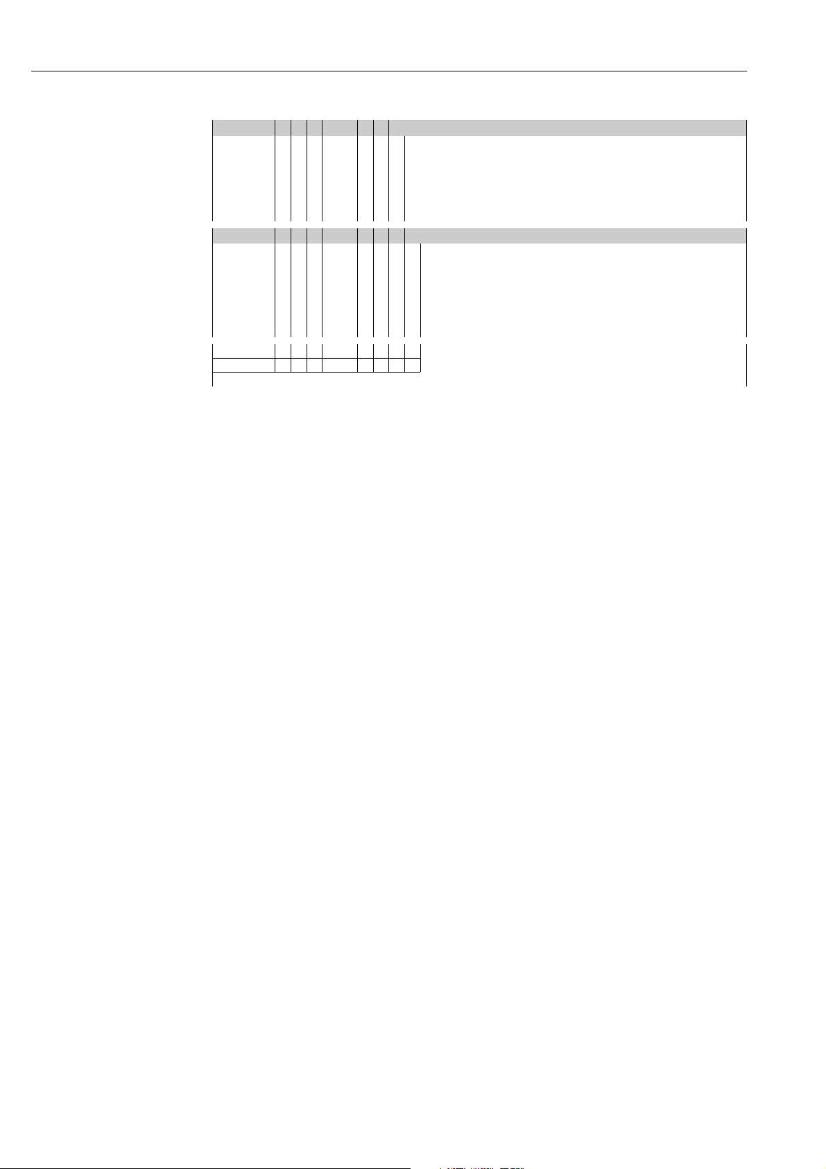
50 Output and menu based operation
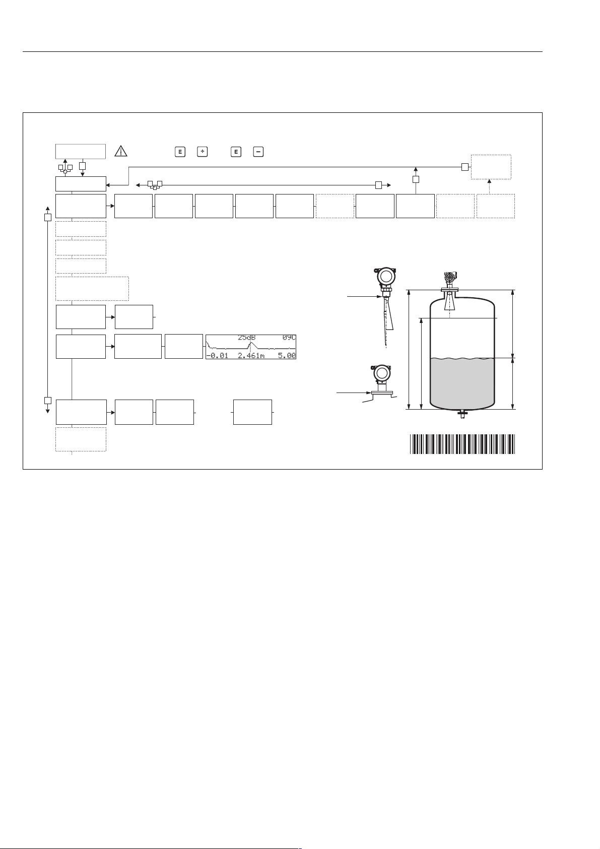
A 4…20 mA HART with VU 331 (4-line alphanumeric display)
B 4…20 mA HART
K 4...20 mA HART, prepared for FHX40, mounting of remote display (accessory)
C PROFIBUS PA with VU 331 (4-line alphanumeric display)
D PROFIBUS PA
L PROFIBUS PA, prepared for FHX40, mounting of remote display (accessory)
E Foundation Fieldbus with VU 331 (4-line alphanumeric display)
F Foundation Fieldbus
M Foundation Fieldbus, prepared for FHX40, mounting of remote display (accessory)
Y Special version
60 Housing
A Aluminium F12-housing, coated, IP65
B 316L F23-housing, IP65/NEMA4x
C Aluminium T12-housing with separate connection compartment, coated, IP65
D Aluminium T12-housing with separate connection compartment, coated, IP65,
overvoltage protection
Y Special version
FMR 230- Product designation (part 2)