Harvard Apparatus Pump 33 DDS User manual

Publication 5419-013 REV1.0
Pump 33 DDS 70-3333
Pump 33 DDS
Dual Drive System
User’s Manual

1Publicaon 5419-013 REV1.0
Table of Contents
SUBJECT PAGE #
Warranty & Repair Informaon 2
Safety Informaon 3
Product Overview - Theory of Operaon 4
Features 4
Independent, Reciprocang and Twin Condion 4
Advanced Connecvity 4
Adjustable Motor Force 4
Power Connecons and Pump Startup 5
Technical Specicaons 6
Operang Humidity 7
Seng Up the Pump 33 DDS (Dual Drive System) 8
Physical Overview 8
Syringe Loading 9
Navigang the Pump 33 DDS Graphical
User Interface
10
Condion Setup & Operaon 10
Graphical User Interface Icon Glossary 11
Independent Condion Setup 13
Independent Condion Run 20
Reciprocang Condion Setup 22
Reciprocang Condion Run 23
Twin Condion Setup 24
Twin Condion Run 28
Sengs 29
Screen Lock & Fast Forward / Fast Reverse 29
Sengs Menu 29
Pump Informaon 29
Seng Time/Date 30
Screen Backlight Adjustment 30
Pump Address 31
Password 31
Baud Rate 32
Force Seng 33
Alarms 33
SUBJECT PAGE #
External Connecons 33-37
USB Pinout 33
USB Virtual Commport Driver Installaon 34
Upgrade Soware 36
RS-232 Pinout 38
RS-485 Pinout 38
Input / Output Connectors 39
Pump Chain Commands 40
Command Convenons and Error Messages 40-41
System Commands 41
Syringe Commands 46
Run Commands 48
Rate Commands 48
Volume Commands 52
Time Commands 53
Digital I/O Commands 54
Internal Commands 54
Maintenance, Baery Replacement
and Troubleshoong
55
Valve Boxes 56
Syringe Manufacturer Volume/Diameter
Reference Table
57
Nominal Flow Rates for Syringe Size
Reference Table
58
Ordering Informaon 58
Contact Informaon 59

Publicaon 5419-013 REV1.02
Warranty and Repair Information
REFER TO SAFETY INFORMATION AND SETTING UP THE
HARVARD APPARATUS PUMP 33 DDS BEFORE PLUGGING
IN THE PUMP.
CAUTION:
For research use only. Not for clinical use on paents.
Manual Descripon
This manual provides all operaonal informaon required to operate
the Pump 33 DDS (Dual Drive System).
Warranty
Harvard Apparatus warranes this instrument for a period of two
years from date of purchase. At its opon, Harvard Apparatus
will repair or replace the unit if it is found to be defecve as to
workmanship or materials. This warranty does not extend to damage
resulng from misuse, neglect or abuse, normal wear and tear,
or accident. This warranty extends only to the original consumer
purchaser.
IN NO EVENT SHALL HARVARD APPARATUS BE LIABLE FOR
INCIDENTAL OR CONSEQUENTIAL DAMAGES. Some states do not
allow the exclusion or limitaon of incidental or consequenal
damages so the above limitaon or exclusion may not apply to
you. THERE ARE NO IMPLIED WARRANTIES OF MERCHANTABILITY,
FITNESS FOR A PARTICULAR USE, OR OF ANY OTHER NATURE. Some
states do not allow this limitaon on an implied warranty, so the
above limitaon may not apply to you.
If a defect arises within the two-year warranty period, promptly
contact Harvard Apparatus, 84 October Hill Road, Holliston,
Massachuses 01746 using our toll free number 1–800–272–2775,
or outside the U.S. call 508-893-8999. Our E-mail address is
[email protected]. Goods will not be accepted for return unless
an RMA (returned materials authorizaon) number has been issued
by our customer service department. The customer is responsible
for shipping charges. Please allow a reasonable period of me for
compleon of repairs or replacement. If the unit is replaced, the
replacement unit is covered only for the remainder of the original
warranty period dang from the purchase of the original device.
This warranty gives you specic rights, and you may have other
rights, which vary from state to state.
Repair Facilies and Parts
Harvard Apparatus stocks replacement and repair parts. When
ordering, please describe parts as completely as possible, preferably
using a part number obtained from our Technical Support
department. If praccal, enclose a sample part or sketch. We oer
a complete recondioning service.
Serial Numbers
All inquiries concerning our products should refer to the serial
number of the unit, located on the rear panel.
Calibraons
All electrical apparatus are calibrated at rated voltage and frequency.
While the ow and volume will stay calibrated, the peak pressure
may vary. Harvard Apparatus recommends an annual calibraon of
the pump.

3Publicaon 5419-013 REV1.0
Safety Information
Please read the following safety precauons to ensure proper use
of your syringe pump. If the equipment is used in a manner not
specied, the protecon provided by the equipment may
be impaired.
To Prevent Hazard or Injury:
USE PROPER POWER SUPPLY
The pump is supplied with an approved power supply and line cord.
To maintain the safety and integrity of the device, use only the
following recommended power supplies.
Globtek Inc.
Model: GTM96600-6048-18-T3 GTM21097-5048-18
Output: 30V DC 2.0 A 30V DC 1.66 A
Input: 100-240V~, 50/60 Hz, 1.5 A 100-240V~, 50/60 Hz, 1.6 A
CAUTION
Refer to Manual
Protecve
Ground Terminal
CAUTION:
Avoid Pinch Hazard
USE PROPER LINE CORD
Use only the specied line cord and power supply for this product
and make sure line cord is cered for country of use. The operang
voltage range for the Pump 33 DDS is 100-240 VAC, 50-60 Hz.
GROUND THE PRODUCT
This product is grounded through the grounding conductor of the
power cord. To avoid electric shock, the grounding conductor must
be connected to earth ground. Before making any connecons to the
input or output terminals of the product, ensure that the product is
properly grounded.
MAKE PROPER CONNECTIONS
Make sure all connecons are made properly and securely. Any signal
wire connecons to the unit must be no longer than 3 meters (except
RS485 pump-to-pump communicaon cable).
OBSERVE ALL TERMINAL RATINGS
Review the operang manual to learn the rangs on all connecons.
AVOID EXPOSED CIRCUITRY
Do not touch any electronic circuitry inside of the product.
AVOID PINCH HAZARD
A pinch hazard may exist between the pusher block and end blocks.
Avoid placing ngers between these points while the pump is
running.
DO NOT OPERATE WITH SUSPECTED FAILURES
If damage is suspected on or to the product do not operate the
product. Contact qualied service personnel to perform inspecon.
ORIENT THE EQUIPMENT PROPERLY
Do not orient the equipment so that it is dicult to manage the
connecon and disconnecon of devices.
PLACE PRODUCT IN PROPER ENVIRONMENT
Do not use the equipment in an explosive environment.
OBSERVE ALL WARNING LABELS ON PRODUCT
Read all labels on product to ensure proper usage.
Publicaon 5419-013 REV1.04
Product Overview- Theory of Operation
The Harvard Apparatus Pump 33 DDS (Dual Drive System)
is a leap forward in syringe pump capability. The Pump 33
DDS has two independent pumping channels controlled by
an intuive touch screen interface.
This mul-purpose syringe pump employs advanced syringe
mechanisms that include a ght gripping, extremely secure
syringe clamp that accommodates syringe sizes 0.5 µl to 60
ml. The Pump 33 DDS oers enhanced ow performance
with high accuracy and smooth ow from 1.02 pl/min to
106 ml/min, syringe size dependent.
The Pump 33 DDS uses a 7” LCD color touchscreen interface
and advanced applicaon soware to control operaon.
The display run screen presents the user with all key
dispensing parameters in real me.
The applicaon soware provides convenient selecon of
common syringe models from a syringe Lookup Table, as
well as inseron of custom syringe specicaons. Syringe
tables containing all major syringe manufacturers allow
simple selecon of any compable syringe size. The system
is then able to calculate the cross-seconal area of the
syringe selected and calibrate the ow rate and volume
accumulaon, displaying real-me operang characteriscs
via on-screen graphics.
I/O interfaces permit external control via an independent
computer or device.
Features
Three operang condions named Independent,
Reciprocang and Twin are available to accommodate
a wide range of setups and experimental protocols.
Independent Condion
Independent Condion allows the Pump 33 DDS to operate
as two separate syringe pumps named P1 & P2. P1 is
syringe posion 1, closest to the touch screen interface
and P2 is syringe posion 2 and is toward the backside
of the unit.
Each syringe will operate independently with dierent
syringe types, size, force, target (volume or me) and ow
rate sengs. This innovave condion allows you to run
two dierent ows at the same me using one instrument.
Reciprocang Condion
In Reciprocang Condion, the syringe channels move
in opposite direcons at the same rate using the same
syringe size and type. When combined with a valve box, the
reciprocang condion can provide the connuous uidic
delivery of a peristalc pump with the accurate, pulseless,
low ow rates provided by a syringe pump.
Twin Condion
The Twin Condion allows both syringes to operate in the
same mode using the exact same syringe type, syringe size,
force, target (volume or me) and ow rate sengs.
The pump also allows the user to combine both ows using
the Ganging feature for higher speed and larger volume
infusion applicaons.
Advanced Connecvity
The Pump 33 DDS comes standard with USB and RS-232
connecons for PC communicaon and RS-485 for pump-to-
pump communicaon. An enre suite of ASCII commands
is available to control the pump remotely with a PC. The
pump contains a footswitch input and digital input/output
for each independent pumping channel.
Adjustable Motor Force
The Pump 33 DDS motors generate up to 70 lbs of linear
force in operaon. This force is sucient to damage
delicate, low-volume syringes, as well as many standard
syringes if pumping viscous uids. The applicaon soware
provides controls to allow you to set a maximum force value
(calculated as a percentage of the maximum value).
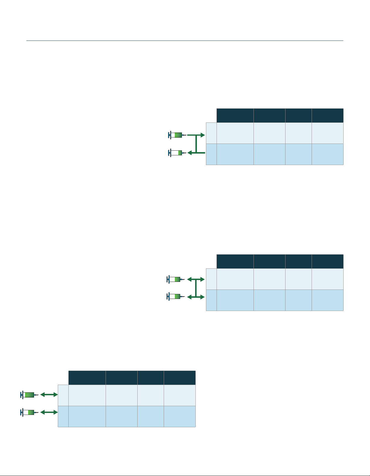
Independent Condion Funconal Table (Mode Dependent)
Reciprocang Condion Funconal Table (Mode Dependent)
Twin Condion Funconal Table (Mode Dependent)
Mode Syringe Rate Target
Volume/TIme
P1
Infuse, Withdraw,
Infuse/Withdraw,
Withdraw/Infuse
Any size/type
0.5 µl - 60 ml
Any within
syringe
capability
Any (mode
dependent)
P2
Infuse, Withdraw,
Infuse/Withdraw,
Withdraw/Infuse
Any size/type
0.5 µl - 60 ml
Any within
syringe
capability
Same as P1
Mode Syringe Rate Target
Volume/TIme
P1 Infuse/Withdraw,
Withdraw/Infuse
Any size/type
0.5 µl - 60 ml
Any within
syringe
capability
Any
P2 Opposite of P1 Same as P1 Same as P1 Same as P1
Mode Syringe Rate Target
Volume/TIme
P1
Infuse, Withdraw,
Infuse/Withdraw,
Withdraw/Infuse
Any size/type
0.5 µl - 60 ml
Any within
syringe
capability
Any (mode
dependent)
P2 Same as P1 Same as P1 Same as P1 Same as P1

5Publicaon 5419-013 REV1.0
Product Overview- Theory of Operation
Power Connecons and Pump Startup
The operang voltage for the Pump 33 DDS is 100-240 VAC,
50/60 Hz through an AC/DC converter provided with the pump.
Please use the provided or recommended power supply. Using
an unapproved power supply will void the warranty.
1. Please ensure that the power switch is in the o posion as shown
in the Pump 33 DDS Rear View Connecons graphic.
2. Plug the power cord in to line voltage. The Pump 33 DDS has a
DC power input connector on the rear of the unit. Plug the barrel
connector into the DC Input on the rear of the unit.
3. Turn on the main power switch located on the rear panel.
4. The Pump 33 DDS touch screen display will illuminate and
display the startup screen while performing self-diagnoscs.
When complete, the unit will display either the Condion Select,
Condion Setup or Condion Run screen depending on the
conguraon during the last use of the pump.
Pump33 DDS Rear View Connecons
CAUTION:
Do not connect RS-485 to rewire devices.
Damage may occur to pump or device.
Pump Channel 1 & 2
Footswitch
Connections
(Footswitch sold separately)
Pump Channel 1 & 2
DIgital I/O
Connections
Main
Power
Switch
RS-232
Serial Input
Future
Expansion
RS-485
Pump-to-Pump
Communication
Ports
DC Input
(Power Supply
included)
USB
Serial Input

Publicaon 5419-013 REV1.06
Unit Specicaon Parameter
Accuracy ± 0.25 %
Reproducibility ± 0.05 %
Linear Force
(Max, per syringe)
70 lbs (31.75 kg) at 100% Force Seng up
to a ow rate of 90 ml/min using a 60 ml
syringe with a 32.573 mm inner diameter.
50 lbs (22.6 kg) at 100% Force Seng for
ow rates 90 ml/min to 106 ml/min using
the same size syringe.
Syringe Size Two Independent syringe mechanisms
(noted as syringe drive P1 & P2)
Minimum 0.5 µl (0.103 mm minimum inner diameter)
Maximum 60 ml (32.573 mm maximum
inner diameter)*
Flow Rate:
Minimum 1.02 pl/min (0.5 µl syringe,
0.103 mm inner diameter)
Maximum 106 ml/min (60 ml syringe,
32.573 mm diameter )
Display 7" WQVGA TFT Color Display with
Touch Screen
Modes of Operaon:
Twin
Condion
Both syringes of the same size operate
idencally (ow rate, direcon & volume)
Independent
Condion
Both syringes operate independently
Reciprocang
Condion
Connuous ow, both syringes of the
same size operate idencally in opposite
direcons
Non-Volale Memory Stores all sengs
Pump Command
Control
ASCII Command Set
Real me Clock Yes, with baery backup (baery included
and required for real me clock)
Connectors:
Power Barrel connector, (-) barrel (+) post 2mm X
5mm male plug
RS-485 IEEE-1394, 6 posion
USB Type B
RS-232 9 pin D-Sub Connector
(I/O) TTL 15-pin D-sub connector (one for each axis)
Footswitch
Connecons
Mini phono jack
Drive Motor Two independent stepper motors
Motor Drive Control MCU controlled
Unit Specicaon Parameter
Step Rate:
Minimum 27 sec/µstep
Maximum 26 µsec/µstep
Stall Detecon Yes, independent axis stall detecon
Input Power 30 V, 1.66 A
Power Supply Input 100-240 VAC, 50/60 Hz, Output 30V
2.0 A, 50 Was
Dimensions (L x D x H) 11” x 15” x 8” (28 cm x 39 cm x 21 cm )
Weight 21 lbs (9.09 kg)
Operang
Temperature
4°C to 40°C (40°F to 104°F)
Storage Temperature -10°C to 70°C (14°F to 158°F)
Operang Humidity 80% @ 25° C ambient temperature
Storage Humidity 20% to 80% RH, non-condensing
Classicaon Class I
Polluon Degree 1
Installaon Category II
Regulatory
Cercaons
CE, ETL (UL & CSA), CB Scheme, EU RoHS,
WEEE
*NOTE: Some larger syringes may be compable with the Pump 33 DDS.
Please contact Technical Support for more informaon.
Technical Specifications

7Publicaon 5419-013 REV1.0
Operating Humidity
The following is a chart of operang humidity versus
temperature for the Pump 33 DDS. Please note as operang
temperature increases, the maximum allowable operang
humidity decreases.
Operang Humidity vs. Temperature Chart

Publicaon 5419-013 REV1.08
Setting up the Pump 33 DDS
Physical Overview
The following diagrams show the important components of the Pump 33 DDS.
Syringe Loading
The Pump 33 DDS syringe mechanisms accommodate syringe sizes 0.5 ul to 60 ml. The pump includes brackets and clamps to hold dierent sizes
and types of syringes for various applicaons. The following uses P1 as the mechanism example. Both syringe pump mechanisms operate in the
same manner.
The call out numbers in the graphic below correspond to the bold numbers in the text that follows.
Pump33 DDS
Top View
Pump Channel 2 (P2)
Pump Channel 1 (P1)
End Block (P2)
End Block (P1)
Lead Screw (P1)
Touch Screen
Knob for Pusher Block (P1)
Lead Screw Release
Knob for Pusher Block (P2)
Lead Screw Release
Pusher Block (P2) Lead Screw (P2)
Guide Rods (P2)
Syringe Clamp/Syringe
Holder Block (P2)
Syringe Clamp/Syringe
Holder Block (P1)
Pusher Block (P1)
Guide Rods (P1)
(1) Syringe Plunger Retaining
Bracket & Retaining Bracket
Tightening Thumbscrews
(14) Clamp Collars
(4) High Force Syringe Clamp
Tightening Thumbscrews
(5) Syringe Holder Block
(6) High Force Syringe Clamp
(7) Low Force Syringe Clamp
Tightening Thumbscrew
(9) Syringe Barrel Retaining
Bracket & Retaining Bracket
Tightening Thumbscrews
(8) Low Force Syringe Clamp
(2) Pusher Block
(3) Pusher Block
Leadscrew Release Knob
(12) Syringe Barrel Flange
(11) Syringe Plunger
(10) Syringe
Plunger Flange
(13) Syringe Barrel

9Publicaon 5419-013 REV1.0
Setting up the Pump 33 DDS
The Syringe Holder Block (5) and Pusher Block (2) are ed
with movable Retaining Brackets (1, 9) which rmly hold
the syringe barrel Flange (12) and Syringe Plunger Flange
(10) during infuse or withdraw modes. The Syringe Holder
Block (5) has two types of syringe clamps used to secure
the syringe barrel to the Syringe Holder Block. They are the
Low Force Syringe Clamp (8) and High Force Syringe Clamp
(6). When loading the syringe into the pump it is necessary
to adjust retaining brackets and to select and adjust the
proper Syringe Clamp (6, 8) for your applicaon.
1. Remove the High Force Syringe Clamp (6) by
unscrewing the two High Force Syringe Clamp
Tightening Thumbscrews.
2. Loosen the two thumbscrews (9) on the Syringe Holder
Block and the two thumbscrews (1) on the Pusher
Block to free the Syringe Plunger and Syringe Barrel
Retaining Brackets.
3. To free the Pusher Block (2) from the Leadscrew,
turn the Pusher Block Leadscrew Release Knob (3)
on the front of the block unl the knob slips into the
slots. This will disengage the Pusher Block and allows
manual Pusher Block adjustment to accommodate
the Syringe Plunger (10). In addion to manual pusher
block adjustment, the user can also move the Pusher
Block using Fast Forward and Fast Reverse buons.
This feature will be discussed in the Condion Setup
secon of this manual.
4. Place the Syringe Barrel (13) on the Syringe
Holder Block (5) and move the Pusher Block (2) to
accommodate the plunger.
5. Make sure the Syringe Barrel Flange (12) and the
Syringe Plunger Flange (10) are held by the Retaining
Brackets (1, 9).
6. Press the Retaining Brackets rmly against the anges
and ghten with the Tightening Thumbscrews (1, 9).
7. Place the Syringe Clamp (6or 8 depending on your
applicaon) over the syringe barrel and secure. Secure
the High Force Syringe Clamp (6) by ghtening the two
High Force Syringe Clamp Tightening Thumbscrews
(4). The High Force Syringe Clamp can invert to
accommodate smaller size syringes. For Low Force
applicaons, place the Low Force Syringe Clamp on the
Syringe barrel. Secure the Low Force Syringe Clamp
by ghtening the Low Force Syringe Clamp Tightening
Thumbscrews (7). The diagrams show the Low Force
and High Force Syringe conguraons.
8. Clamp collars (14) are included to protect fragile
syringes. The collars are placed and ghtened along
the guide rides to allow a mechanical stop. When the
pusher block reaches the ghtened clamp collar, it will
stall, stopping the acve pump.
Low Force Syringe Clamp Examples
Pump 33 DDS Showing Syringes Installed with Low Force (P1)
and High Force (P2) Syringe Clamps
High Force Syringe Clamp Examples
Note: The picture on the right shows a small size high force syringe secured
with the inverted High Force Syringe Clamp
Pump
Channel 1 (P1)
Pump Channel 2 (P2)
Low Force
Syringe Clamp
Example
High Force
Syringe Clamp
Example

Publicaon 5419-013 REV1.010
Navigating the Pump 33 DDS Graphical User Interface
The Pump 33 DDS employs a buon enabled Graphical User
interface controlled with a large 7” LCD Color Touchscreen display for
quick and easy setup.
There is a setup and run screen for all three operaon condions
Independent, Reciprocang and Twin. The setup and run screens
for all three condions are similar with common buons. There are
small funconal dierences for each condion based on the features
that condion supports.
When you rst turn on the unit aer delivery from the
Harvard Apparatus factory, the following start up screen
will briey appear.
Then the unit will display the Condion Select Screen. If the
Condion Select screen does not appear, please press the back
buon (see Independent Condion below) unl you enter the
Condion Select Screen.
Select the desired operaonal condion and you will enter the
setup screen for that condion. The following explains the graphical
user interface for all three operang condions (Independent,
Reciprocang and Twin).
Start Up Screen
Condion Select Screen

11Publicaon 5419-013 REV1.0
Graphical User Interface Button Glossary
The following buons are part of the Pump 33 DDS (Dual Drive System) graphical user interface.
Mode Select – Sets Pump Channel Mode
Syringe Select – Sets Syringe Type & Size
Target Select – Sets Target Volume or Time
Rate Select – Sets Flow Rate
Run/Stop Pump Channel 1 (P1) –
Starts / Stops Pump Channel 1 (P1)
Only in Independent Condion.
Run/Stop Pump Channel 2 (P2) –
Starts / Stops Pump Channel 2 (P2)
Only in Independent Condion.
Run/Stop Pump Channel 1 & 2
(P1 & P2) – Starts / Stops both
Pump Channel 1 (P1) and
Pump Channel 2 (P2).
Return to Previous Screen – Returns
the user to the previous screen.
System Sengs – Enters System Sengs Menu to
adjust Time/Date, Backlight, Pump Address, Baud
Rate, Password, Force, Alarm, Pump Informaon
and Upgrade Soware features.
Fast Forward / Fast Reverse – Automacally advances or reverses
the Pump Channel 1 (P1) and / or Pump Channel 2 (P2) pusher
blocks. Select P1 and/or P2 to enable the feature for that
pump channel.

Publicaon 5419-013 REV1.012
Graphical User Interface Button Glossary
Minimum Value Allowed – Used to select the
minimum value allowed for the parameter entry.
Maximum Value Allowed – Used to select the
maximum value allowed for the parameter entry.
Run Preview Screen – Brings the user to
the Run Screen.
Accept – Used to accept the parameters/sengs on
a screen and advance to the next menu.
Cancel – Used to cancel any changes/entries on
a screen in the menu.
Reset Counters Pump Channel 1 (P1) – Clears
the counter/mers for Pump Channel 1 (P1) for
Independent Condion Only.
Reset Counters Pump Channel 2 (P2) – Clears
the counter/mers for Pump Channel 2 (P2) for
Independent Condion Only.
Reset Counters – Clears the counter/mers for
Reciprocang and Twin Condion.

13Publicaon 5419-013 REV1.0
Independent Condition Setup
Independent Condion allows the Pump 33 DDS to operate as two separate syringe pumps named P1 & P2. P1 is syringe posion 1 (Channel 1),
closest to the touch screen interface and P2 is syringe posion 2 (Channel 2) and is toward the backside of the unit.
Each syringe will operate independently with dierent syringe types, size, force, target (volume or me) and ow rate sengs. This innovave
condion allows you to run two dierent ows at the same me using one instrument.
Select “Independent” from the Condion Select Screen.
The Independent Condion Setup Screen will appear. There are two secons to each Condion Setup screen. The top two thirds of the screen is
dedicated to the mode, syringe type/size, ow rate and target volume or me setup for Pump Channel 1 (P1) and Pump Channel 2 (P2).
Condition Select Screen (Independent Condion Selected)

Publicaon 5419-013 REV1.014
Independent Condition Setup
Independent Condion Setup Screen BUTTON Guide
Independent Condion Setup Screen
The boom of the screen contains the Run, Fast Forward / Fast Reverse and System sengs buons. This manual addresses the Run funcons aer
each condion setup secon. The Sengs secon of this manual covers the system seng funcons.
The following is a summary of the Independent Condion Setup Screen with detailed explanaon of each buon funcon.

15Publicaon 5419-013 REV1.0
1) MODE SELECT - Select the Mode for Pump Channel 1 & Pump
Channel 2. Press the Mode Select buon for either Pump Channel 1
(P1) or Pump Channel 2 (P2). The following screen will appear. The
Mode for Pump Channel 1 (P1) and Pump Channel 2 (P2) can be
set individually.
The four Modes are:
a. Infuse Only - The syringe will operate in infuse mode only.
Facing the Pump 33 DDS, the pusher block will push the
syringe plunger from le to right at the set ow rate and
volume/me.
b. Withdraw Only - The syringe will operate in withdraw mode
only. Facing the Pump 33 DDS, the pusher block will pull the
syringe plunger from right to le at the set ow rate and
volume/me.
c. Infuse/Withdraw - The syringe will operate in Infuse/
Withdraw mode. Facing the Pump 33 DDS, the pusher block
will push the syringe plunger from le to right at the set
ow rate and volume while infusing and will then pull the
syringe plunger from right to le at the set ow rate while
withdrawing. The infuse and withdraw ow rates can be
dierent. For example: An experiment may require a low
ow rate for infusion but require a fast withdraw rate for
quick syringe rell.
d. Withdraw/Infuse - The syringe will operate in Withdraw/
Infuse mode. Facing the Pump 33 DDS, the pusher block will
pull the syringe plunger from right to le at the set ow rate
and volume while withdrawing and will then push the syringe
plunger from le to right at the set ow rate while infusing.
The withdraw and infuse ow rates can be dierent.
Select the desired modes for both P1 and P2. The modes can be set
dierently while in Independent Condion. Once selected, the mode
buon will turn green. Press the Green check buon in the boom
right hand corner of the screen to accept the Mode selecons for P1
and P2. Press the Red X to discard the selecons and return to the
Independent Condion Setup screen.
Independent Condition Setup
Independent Condion Mode Select Screen
Select Syringe Screen Showing Force Alarm
2) SYRINGE SELECT - Select the syringe size and type for Pump
Channel 1 (P1) & Pump Channel 2 (P2).
Press the Syringe Select buon for either Pump Channel 1 (P1) or
Pump Channel 2 (P2).
Note: Unlike the Mode Select secon, the Independent Condion
syringe selecon requires the user to select and set the P1 syringe
rst and then select and set the P2 syringe.
The following screen will appear.
The Pump 33 DDS has many syringe manufacturers listed in the
Select Syringe table. The le hand side of the Select Syringe screen
lists the syringe manufacturer and type. The right hand side of the
Select Syringe screen sets the syringe size. In the example above a
50 ml, Hamilton 1000 Series syringe is selected. Once the proper
syringe manufacturer, type and size has been selected, press the
Green check mark buon to accept or press the Red X buon to
return to the Independent Condion Setup screen.
Depending on the syringe type and size, the Pump 33 DDS may
display a force warning. A high set force could damage a small glass
syringe. In this case, the pump will alert the user to lower the Pump
33 DDS linear force. Please see the sengs secon for informaon
about adjusng linear force.
Select Syringe Screen

Publicaon 5419-013 REV1.016
Independent Condition Setup
The Pump 33 DDS also supports syringes not specically listed in the
syringe table through the Custom Syringe Selecon. Select Custom
Syringe from the syringe selecon table.
The Custom Syringe Sengs Screen will appear. Enter the inner
diameter and capacity of the syringe and press the green check mark
buon to accept and return to the Independent Condion setup
screen. The syringe capacity will appear in either µl or ml. Pressing
the units text will toggle the inputs between µl and ml.
Perform the same acons on the P2 Syringe Select to set the
syringe for Pump Channel 2 (P2).
Note: the Custom Syringe diameter range is 0.1 mm to 45 mm and
the Custom syringe capacity is 0.5 to 1000 ml. This range falls
outside of the syringe size range specied in this manual because
some larger syringes may be compable with the Pump 33 DDS.
Please contact Technical Support for more informaon.
Select Syringe - Custom Syringe Screen
Custom Syringe Sengs Screen
Set Rate Screen (Infuse Mode Shown)
3) RATE SELECT – Select the ow rate for Pump Channel 1 & Pump
Channel 2. Independent Condion requires the user to enter a
ow rate for the selected mode on both P1 & P2. The user will
need to enter either one or two rates depending on the mode
selected. Infuse and Withdraw modes require one rate while
Infuse/Withdraw and Withdraw/Infuse require two rates.
Press the Rate Select buon for Pump Channel 1 (P1) or Pump
Channel 2 (P2). The Set Rate screen will appear. Infuse mode is
shown in the screen shot below. There are four selectable entries
on the Set Rate screen.
Flow Rate - Enter the ow rate in the number entry box using
the keypad located on the right hand side on the screen. When
selecng Withdraw mode, use the same procedure to enter the
Withdraw rate.

17Publicaon 5419-013 REV1.0
Units - Set the units for the desired ow rate by touching the units
found on the right of the number entry box. The following Select
Units popup box will appear. Select the volume units from the le
hand side of the Select Units popup and me units from the right
hand side. Press the green check mark buon to accept and return
to the Set Rate screen.
Note: All other selectable entries on the Set Rate screen will be
grey unl the current entry is complete.
Set Flow Rate Units (Select Units)
Set Rate Screen with MIN Flow Rate Selecon
Infuse or Withdraw Mode Target Volume Seng
Set Rate Screen with MAX Flow Rate Selecon
Press the green check mark buon to accept and return to the
Independent Condion Setup Screen.
4) TARGET SELECT – Select the target volume or me for Pump
Channel 1 & Pump Channel 2. The TARGET SELECT parameter
entries are dierent for Infuse and Withdraw only versus
Infuse/Withdraw and Withdraw/Infuse.
Set Target Volume - Set the Target Volume for Pump Channel
1 & Pump Channel 2. Independent Condion requires the user to
enter a Target Volume or Time for the selected mode on both P1
& P2.
On the Independent Condion setup screen, press the Target
Select buon for Pump Channel 1 (P1) or Pump Channel 2 (P2).
The Set Target Volume or Time screen will appear. Infuse and
Withdraw modes allow the user to select either a target volume
or me, while Infuse/Withdraw and Withdraw/Infuse allow a
target volume or connuous operaon. Select the Target Volume
entry box. The box will become white to show it is acve. Either
select the required volume or select the MAX buon to set the
maximum volume of the set syringe.
Set Maximum and Minimum Flow Rate Buons – There are
two buons in the boom le quadrant of the Set Rate screen.
Selecng either the MAX or MIN buon will automacally set the
maximum or minimum ow rate for the set syringe.
Note: Selecng either MAX or MIN will overwrite any previous ow
rate entry.
Independent Condition Setup

Publicaon 5419-013 REV1.018
Infuse or Withdraw Mode Target Time Seng
Infuse/Withdraw or Withdraw/Infuse Set Target Volume Screen
Setup Screen Showing Target Select “Connuous Operaon”
Independent Condition Setup
Select the Target Time entry box to enter the target me. The me
can be entered in HH:MM:SS or sec. The user can toggle between
HH:MM:SS or sec by pressing the me units to the right of the target
me entry box.
5) Fast Forward / Fast Reverse Buons
The Fast Forward buon advances the pusher block from le
to right (infuse direcon) for P1 and/or P2. These buons are
available at the boom of all main Condion setup and Run
screens. The Fast Reverse buon advances the pusher block
from right to le (withdraw direcon) for P1 and/or P2. This is
useful to set the pusher block in the correct locaon for the given
applicaon.
Note: The user can move the pusher blocks manually. Please see
the Syringe Loading secon for informaon on moving the P1 and
P2 pusher blocks manually.
To use the Fast Forward and Fast Reverse buons, select either
the P1 and/or P2 buons located at the boom center of all
main condion setup and run screens. Once selected, the buon
will turn bright green. Then use the Fast Forward/Fast Reverse
buons to the right of the P1 and P2 buons to move the P1 and
or P2 pusher blocks. The Fast Forward/Fast Reverse buons must
remain pressed to move the pusher block. Once released the
pusher block will stop immediately. During operaon, the Pump
33 DDS will display a red message box showing the pusher block
direcon. The following examples are from the setup screen. This
same funconality is available in the condion run screens.
Note: Certain buons are disabled in certain condions. Stall
detecon is disabled during Fast Forward/Fast Reverse operaon.
The Infuse/Withdraw and Withdraw/Infuse modes allow only
a target volume. The Target Time selecon will not be available.
Select the required volume by entering the Target Volume and
pressing the green check mark buon. The pump will alternate
infusions and withdrawals up to the syringe capacity unl the target
volume has been infused. The last phase of an Infuse/Withdraw or
Withdraw/Infuse will return the pusher block to its original locaon.
For example, seng an Infuse/Withdraw target volume or selecng
the Connuous Operaon buon of 50 ml with a 50 ml syringe will
infuse 50 ml, then withdraw 50 ml. Seng a Withdraw/Infuse target
volume of 75 ml with the same syringe will withdraw 50 ml, infuse
50 ml, withdraw 25 ml, and infuse 25 ml.
Connuous Operaon: Selecng “0” as a target volume or selecng
the Connuous Operaon buon in the Infuse/Withdraw and
Withdraw/Infuse modes allows connuous operaon unl the user
stops the pump channel. For example: Selecng “0” as a Target
Volume or selecng the Connuous Operaon buon for a 50 ml
syringe using Infuse/Withdraw mode, would set the syringe to infuse
50 ml then withdraw 50 ml. This will repeat indenitely unl the user
stops the pump channel.

19Publicaon 5419-013 REV1.0
Independent Condition Setup
Pump Channel 1 (P1) & 2 (P2) Fast Forward Feature
Pump Channel 2 (P2) Fast Reverse Feature
Pump Channel 1 (P1) Fast Reverse Feature
Pump Channel 1 (P1) & 2 (P2) Fast Reverse Feature
Pump Channel 1 (P1) Fast Forward Feature Pump Channel 2 (P2) Fast Forward Feature
Table of contents
Other Harvard Apparatus Water Pump manuals


Popular Water Pump manuals by other brands


IKA
IKA Vacstar control operating instructions

Dover
Dover PSG WILDEN Pro-Flo SHIFT PS1 Engineering, operation & maintenance

BUSCH
BUSCH R 5 RA 0160 D instruction manual

MULTIQUIP
MULTIQUIP MQ41TDH Operation and parts manual

Theiling
Theiling River 2700 Operation manual

Dover
Dover PSG ALL-FLO IOM A025 Series Installation operation & maintenance data

Biral
Biral EBZ-E Installation and operating instructions

Intex
Intex Quick-Fill AP643 owner's manual

Mira
Mira Enhance Installation & user guide

Fuelab
Fuelab 40401-c Operating and installation instructions

ProMinent
ProMinent Sigma / 2 Basic S2Ba operating instructions

IWAKI AMERICA
IWAKI AMERICA Walchem EWN-Y Quick start programming guide