Harvest TEC 239DM User manual

1
239DM - 20
5/21
OWNER’S MANUAL
Model 239DM
Dye Sprayer Marking System
Accessory upgrade to CNH DIA Moisture kits 439618, 48189657, & 90420182
Forage Harvester

2
Harvest Tec 739DM Table of Contents
Page
Introduction & Tools Needed
2
Installation of Dye Sprayer Tank & Plumbing
System Wiring
Installation of Plumbing
3
4
5-7
Plumbing Diagram
Plumbing Troubleshooting
7
7
Baler Display Integration
8-18
Case LB334/434 & New Holland Big Baler Series
(MY2020 and Prior)
Case LB436HD & MY2021 and later LB4 Series
New Holland 340/1290HD & MY2021 & later Big Baler Series
8-14
15-18
Display Options
Operation of Tablets
Operating the Harvest Tec 700 Series System
Filling Tank & Start Up
Operation Instructions Automatic or Manual Mode
19
20-23
24-31
32
32
Pin Outs
33-36
Parts Breakdown
37
Warranty
38
Introduction
Congratulations on purchasing a Harvest Tec Dye Sprayer Marking System. When attached to a DIA star
wheel moisture sensor for Case/New Holland large square balers the 239DM allows you to visibly mark the wet
areas on your bales. The system includes the tank, pump, plumbing, mounting hardware and necessary
harnesses. There is a parts breakdown in the back of the manual to reference if replacement parts are needed.
All replacement parts and dye will be ordered through your local CNH dealer.
Tools Needed
Standard wrench set
Hammer
Straight edge
Standard socket set
Tape measure
Metal drilling and cutting tools
Center punch
Marker

3
Installation of Dye Sprayer Tank & Plumbing
Installation of Mounting Bracket & Tank –CASE & New Holland Large Squares
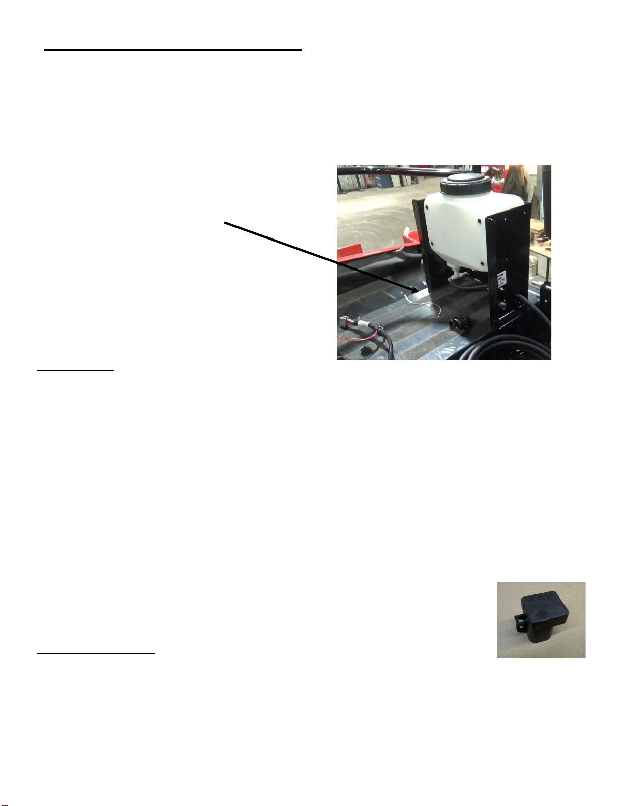
Locate the tank and mounting bracket assembly. Looking at Figure 1 decide where a desirable mounting
location will be the most convenient and work the best for the user.
a. Once tank location is decided, mark the mounting holes and drill bit.
b.
System Wiring
Setting up Tractor
1. Connect the red and black eye-loop connectors from 006-765IC Tractor Power/Communication harness
DIRECT to tractor battery. Route 18 pin plug to drawbar of tractor and the other leg of the harness with the 12
Pin and 4 Pin connector into the cab of the tractor.
2. 006-6673 ISO Communication Module (ICM) mounts in the cab of the tractor and connect 006-765IC 12 pin
header harness to it.
3. Connect 006-765CPH key power harness to 4 pin plug on 006-765IC harness near ICM. Securely fasten to
key power outlet in cab of tractor
4. Secure wires with zip ties.
Setting up baler.
1. Route 006-765BN harness from draw bar of baler back toward Balers ECU
2. Remove 006-7303CMS star wheel harness plug from Baler ECU CAN 2 connection and attach 006-765BN
to same connection of 006-7303CMS harness.
3. Remove 006-4640J resistor plug from the 006-7303CMS harness and attach 006-
765VN to same connection of 006-7303CMS. Reattach 006-4640J to port on 006-765VN.
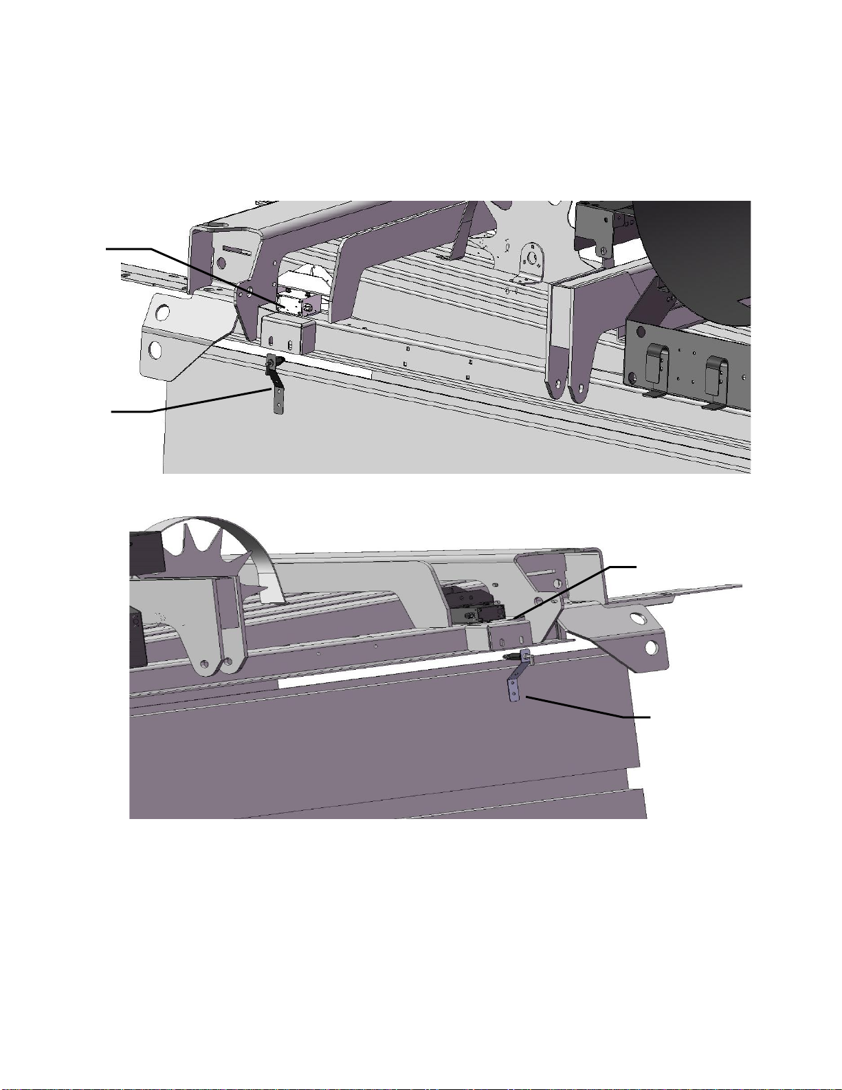
4. Locate the CAN Port 1 on the baler ECU. Remove 6 pin active terminator (X504) from
CAN 1 (Figure 2) and attach active terminator to 006-765VN harness 6 pin plug
5. Attach 006-765VN harness to Baler ECU CAN 1 plug
Setting up Dye Marker
1. Locate the wiring harness (006-765IDM3) supplied in the 239 dye Sprayer Marking Kit.
Connect to triangle plug on the metal frame of the dye marker.
2. Route Dye Marking harness (006-765IDM3) to main star wheel harness (006-7303CMS) and attach it to
triangle CAN plug found near star wheels. Secure with zip ties
Figure 1
Common New Holland and CASE IH baler
mounting position
Figure 2

4
System Wiring Diagram

5
Installation of Plumbing
To most effectively mark the wet spots in any bale, Harvest Tec recommends that the nozzles are
mounted directly above or below the Star Wheels. To get the best spray pattern focused directly on
the wet spot of the bale the nozzles will need to be approximately above the bale that is being
marked. A small notch may need to be cut to increase surface area of the bale being marked.
1. Once you have the tank and mounting bracket securely fastened to the baler, locate parts A, B,
C, D & E pictured below in Figure 2. Assemble in the following order: (A) Elbow | (B) nozzle
holder | (C) check valve | (D) reducing bushing | (E) tip as pictured below.
*****Note: All parts should be thread taped*****
2. Once the nozzle holders are fastened to the balers, route the 3/ to the tips. Make sure to
fasten the hose securely but avoid pinching the lines. (Plumbing Diagram pictured in Figure 3)
*****Keep from routing the hose in the way of moving parts on the baler*****
3. Attach drain hose top hose barb fitting at bottom of tank. Run hose to a secure point and attach
valve assembly.
J
Check Valve
004-1207V
A
Elbow
003-SE14F
C
Brass Tip
004-TX-5
F
Straight Fitting
003-A1418
G
Quick Connect
004-1207H
H
Rubber Gasket
004-1207W
I
Tip Screen
004-1203-100
E
Nozzle Holder
001-4216
B
Nozzle Body
004-4722
D
Nozzle Cap
004-4723
Figure 2

6
Installation of Plumbing (continued)
4. Install the tip and nozzle holder assemblies in the suggested locations pictured shown below.
a. Make sure that the tip assemblies (A) are mounted in line with the star wheels (B) so that
the system is marking the wet spots of the bale.
Example A
A
B
A
B
Example B

7
Installation of Plumbing (continued)
Plumbing Diagram
Common Question
1. Is the marking dye safe for livestock consumption?
The Dye Marker uses red-colored, food-grade dye and is safe for all livestock.
2. How do I bleed the air out of the lines properly?
the dye marker until the air is pushed out of the lines.
Troubleshooting
Problem
Possible Cause
Solution
The tips are not spraying Dye
1. The system is out of dye.
2. There is air in the lines,
preventing a steady mist
coming from the tips.
3. Damaged/pinched hose.
4. Tip is plugged.
5. Set point is set too high
1. Check the tank for solution. If the tank
is empty, refill and bleed air from lines.
2. Remove the tips from the check valves
and using the priming button bleed the
air out of the lines.
3. Inspect all the hose making sure the
lines are damaged or pinched.
4. Removed the tip from the bushing and
inspect, clean is necessary.
5. Lower the set point level at which the
user would like to have the bales
marked at.
Tank
005-9019
Pump
007-4120LF
002-9003AS
Hose Barb Tee
003-T3838
Brass Tip
004-TX-5
Drain Valve
002-2216
Figure 3

8
Baler Display Integration
Case LB334/434 & New Holland Big Baler Series (MY2020 and Prior) (continued)
The ISOBUS Monitor utilizes touch screen options to make selections. Selections are made by finding the
desired selection and pressing the touch screen icon. All buttons are labeled and color coded.
When the moisture system is connected thru the baler CAN1 and powered on the first time it is necessary to
load the object pools to the Virtual Terminal (VT).

9
Case LB334/434 & New Holland Big Baler Series (MY2020 and Prior) (continued)
Icon (1) indicates that the object pools are in the process of loading and saving to the VT. Note that if the
language selection of the VT is changed, the corresponding object pool must be reloaded to the VT. The
object pool loading process takes approximately two minutes to complete.
Once the object pools have been loaded and Icon (1) disappears from the upper left corner of the display,
press the NEXT IMPLEMENT button (2) and verify that the moisture system object pool appear on the Virtual
Terminal.
After verifying that the moisture system object pool is loaded and the operating screens are displayed on the
VT, press the NEXT IMPLEMENT button (3) to return to the baler work screen page.
Press the bottom button of the Menu Bar with the down arrow in corner (4) on the side of the screen to
continue down the Menu Bar below the USER SETTING icon.
2
4
1
3
6

10
Case LB334/434 & New Holland Big Baler Series (MY2020 and Prior) (continued)
Scroll through the Menu bar until the INFORMATION icon (5) is visible. Press the INFORMATION button so
the Information page appears. Verify that the controller software loaded to the baler is version 4.2.0.0 or
higher. If not, contact the dealer to update firmware in Baler Control Module (BCM). If the controller software
displays version 4.2.0.0 or higher proceed to configuring the baler for the moisture system by pressing the
MACHINE SETUP button (6).
Once the MACHINE SETUP icon has been selected, the Machine Setup page will appear, and the icon will be
backlit in orange. Press the MACHINE SETUP icon (7) again to go to the second page of the Machine Setup.
The second page of the Machine setup is identified by the three gray buttons in the Menu Bar. Press and
hold the third gray button (8) for 10 seconds or until the display switches to displaying Dealer Mode.
7
6
8
4.2.0.0
5

11
Case LB334/434 & New Holland Big Baler Series (MY2020 and Prior) (continued)
Once Dealer Mode has been entered, select the down arrow in the Menu Bar (9) to scroll to the second
the
Select the proper configuration setting from the pop-up menu (11), based on the configuration of your
moisture system. This configuration setting allows the baler to properly display the information it is receiving
from the moisture system on the baler working screen. DCP
10
11
9

12
Case LB334/434 & New Holland Big Baler Series (MY2020 and Prior) (continued)
Once the configuration has been set press the MACHINE SETUP icon (12) to return to the Machine Setup
Screen and the Menu Bar.
Press the arrow down button at the bottom of the Menu Bar (13) to scroll down thru the Menu Bar until you
reach the SCREEN SETUP pages.
Select the icon for SCREEN SETUP 1 (14) so the Screen Setup 1 screen appears. Select how you would like
to have the screen configured to show a combination of baler and moisture system information by selecting
the boxes. When you select one of the boxes, a pop-up screen will appear that shows the selections
available.
14
13
12
11

13
Case LB334/434 & New Holland Big Baler Series (MY2020 and Prior) (continued)
Selections related to the moisture system include MoistureMoisture Baleand are highlighted by
arrows above and in the next picture. Scroll to additional options in the popup window by pressing the down
arrow on the side of the popup window (15).
Once the Screen Setup pages have been configured, scroll back up to the top of the Menu Bar by pressing
the top button in the Menu Bar with the up arrow (16).
Select the FIELD SETTING icon (17) and adjust the Moisture Alarm Settings in the Field Setting Screen.
Note that the low moisture alarm must be set lower than the high moisture alarm. The moisture alarms can be
turned off by setting the low setting <9% and the high setting >70%. When the alarms are turned off, they will
say OFF next to the values. Select the MAIN SCREEN 1 icon (18) from the Menu Bar.
16
17
15
18

14
Case LB334/434 & New Holland Big Baler Series (MY2020 and Prior) (continued)
Verify that your MAIN SCREEN 1 and MAIN SCREEN 2 are configured as you would like them displaying the
information you would like visible during operation. During operation, information for the moisture system that
you have chosen to display will be displayed on the Baler Work Screen.
Cycle back and forth between the Baler Work Screen and the Moisture System Work Screen by pressing the
NEXT IMPLEMENT button (19) during operation.
Harvest Tec Icons signified by arrows 19-22 are as follows:
(19) Next Implement Button
(20) Moisture Content %
(21) Last Bale Average Moisture Content %
(22) Moisture Status Icon
The status icon (22) indicates the system is connected to the
A) Not in an application mode
B) Paused through
a. Manual Pause
b. Baler End of Row (EOR) Pause (PTO
speed < 600 rpm)
20
21
22
19

15
Baler Display Integration
Case LB436HD & MY2021 and later LB4 Series New Holland 340/1290HD & MY2021 and later
Big Baler Series
Follow the steps below to setup the integration of the Moisture System into the baler display.
1. Select the baler Setup tab in the top right corner of the baler run screen.
2. Open the Diagnostics tab by pressing the (stethoscope icon) and select the System Information
tab.

16
Case LB436HD & MY2021 and later LB4 Series New Holland 340/1290HD & MY2021 and later
Big Baler Series (continued)
3. On the System Information page press and hold the first blank square box under the down arrow
on the right side of the screen for 10 Seconds.
4.
enter the Code 1379 when the numbers appear.
the balers home screen.

17
Case LB436HD & MY2021 and later LB4 Series New Holland 340/1290HD & MY2021 and later
Big Baler Series (continued)
5. Select the baler Setup tab in the top right corner of the baler run screen. Then press Machine
Configuration from the baler setup page (wrench icon at top).
6. Select the Moisture Sensor line on the Machine Configuration screen. On the next screen that
appears select DCP from the drop down
The moisture sensor selection will now read DCP on the Machine Configuration page.

18
Case LB436HD & MY2021 and later LB4 Series New Holland 340/1290HD & MY2021 and later
Big Baler Series (continued)
The current bale moisture content will now
display above the baler next to the water
droplet and the previous bale moisture will
display next to the bale in above the are above
the bale chute (below).
Previous Bale Moisture
Current Bale Moisture

19
Display Options
Optional Baler Tablet Integration
The 700 series is easily integrated into the CNH Baler VT. This allows the operator to monitor both
real time baler settings and Harvest Tec system parameters on one screen to ensure the most
precise application to every bale.
The 700 series also features the use of a separate display with an option tablet
.
Follow SCREEN MENUS section to set and operate the moisture system.
Optional Tablet Display
The iOS or Android Tablet displays offer the ability to communicate with the 700 series system via
hard-wired connection to the ISO Communication Module (ICM). Through the free Precision Baling
App, the operator can set real time baling parameters to monitor every bale. This provides a multi-
use option while utilizing the improved app to select objects, enter data, and easily switch through
operational screens. The Tablet Display offers easy integration by connecting a charging cable to the
additional USB port on the ICM module. Once connected, the Harvest Tec applicator will display
upon opening the app and powering up the system. Tablets can be used in addition to integrated
baler VT display.
*Made for iPad®(3rd generation minimum) or Android Tablet (Does not work with Amazon
Fire).
Required to be running the most current operating system or one version previous.
*iPad is a trademark of Apple Inc., registered in the U.S. and other countries.
Precision Baling App

20
Operation of Tablets
Turn On/Off Tablet using the Sleep/Wake button
iPad
Turn iPad ON: Hold down the Sleep/Wake button until Apple logo appears. iPad will take a moment
to load.
You can lock iPad and put it to sleep when you are not using it.
Locking iPad puts the display to sleep, saves the battery, and
prevents anything from happening if you touch the screen.
Turn iPad OFF: Hold down the Sleep/Wake button for a few seconds until the slider appears
onscreen, then drag the slider to the right.
Android
Turn Tablet ON: Hold down the Sleep/Wake button until logo appears. Tablet will take a moment to
load.
You can lock tablet and put it to sleep when you are not using it.
Locking the android tablet puts the display to sleep, saves the
battery, and prevents anything from happening if you touch the
screen.
Turn Tablet OFF: Hold down the Sleep/Wake button for a few seconds until the onscreen appears,
then drag the slider to the right.
*Amazon Fire Tablet Does Not Work for Applicator*
Sleep/Wake
Button
Sleep/Wake
Button
Table of contents
Other Harvest TEC Paint Sprayer manuals
Popular Paint Sprayer manuals by other brands

Graco
Graco Ultra Operation, parts

Titan
Titan Focus 700 operating manual

Anest Iwata
Anest Iwata Mazeco AMM-711 instruction manual

Krautzberger
Krautzberger MC1 operating instructions

Campbell Hausfeld
Campbell Hausfeld PS240C Operating and assembly instructions

Earlex
Earlex SPRAY SYSTEM HV 1900 operating instructions