Harvestman R1982 POLIVOKS VCF User manual

MODEL R1982 “POLIVOKS VCF”
OPERATOR’S MANUAL
Classic Voltage-Controlled Filter from the Soviet Union.
CUTOFF FREQUENCY
RESONANCE
MIXER
POLIVOKS
LP BP

THE HARVESTMAN-R1982
“POLIVOKS VCF”
USERʼS MANUAL
Table of Contents
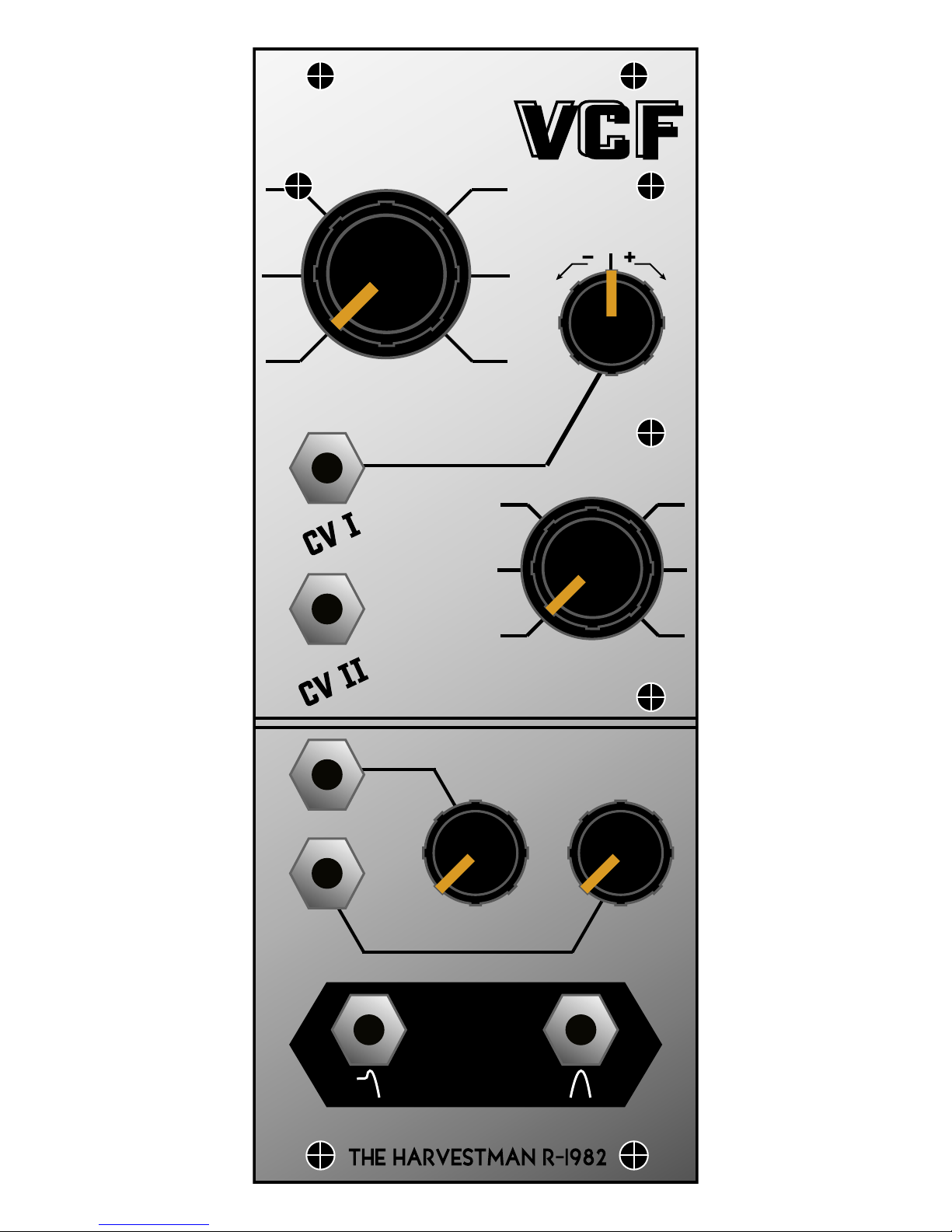
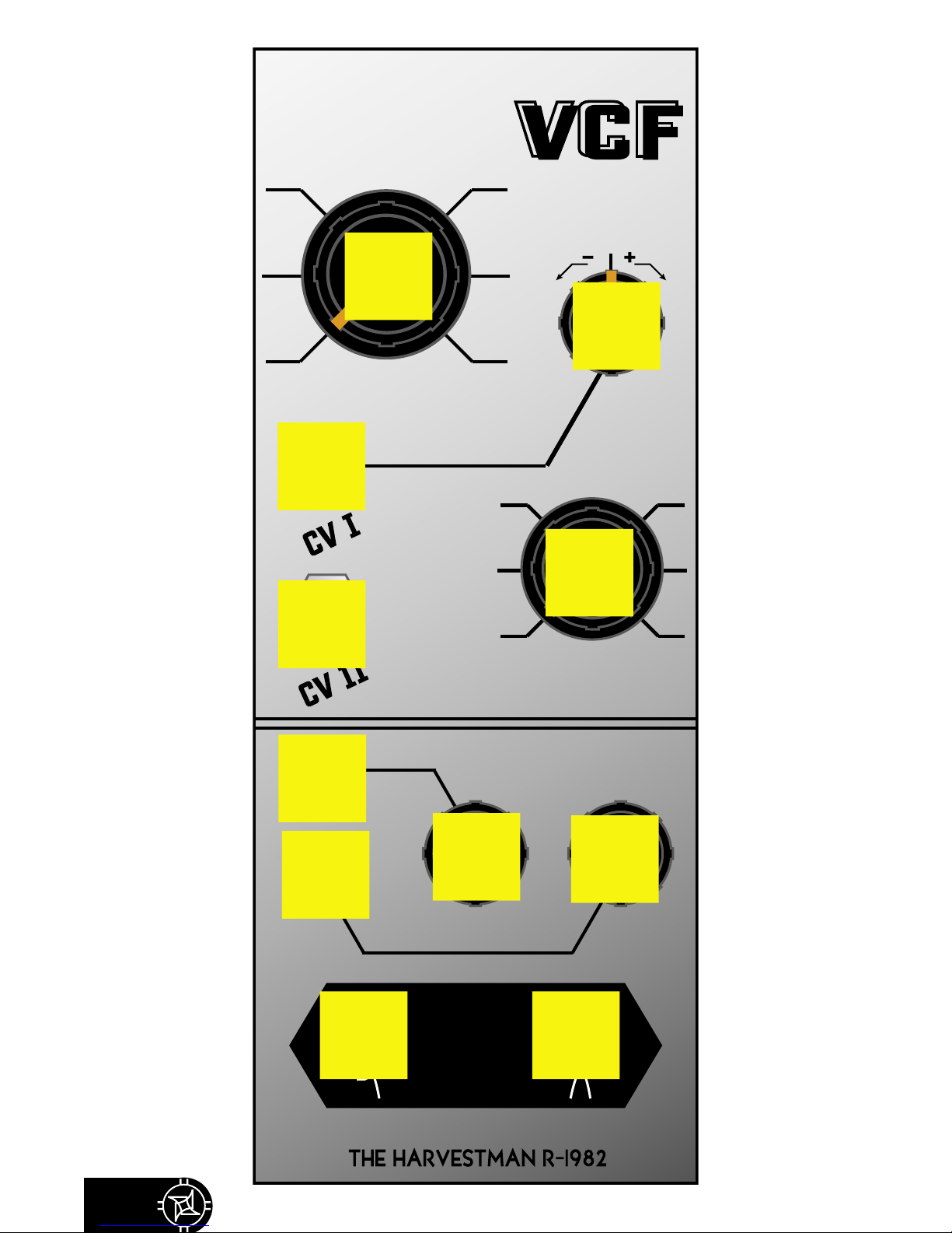
Front Panel Key
Introduction
Configuration
- Power cable orientation
Tips and Tricks
Warranty
4
CUTOFF FREQUENCY
RESONANCE
MIXER
POLIVOKS
LP BP
AB
C
DE
F
GHI
J K

5
A Manual cutoff frequency control
Controls the frequency at which spectral components of the input signal become at-
tenuated.
B Cutoff CV multiplier (bipolar)
Adjusts the level of incoming control voltages on input CV1, applied to the cutoff fre-
quency parameter. This is a bipolar multiplier. The 12 oʼclock setting stands for zero. Values
counterclockwise of this point invert the control voltage, while clockwise settings do not.
C Cutoff CV input 1
Accepts a control voltage for modification of the filterʼs cutoff frequency. Governed by
the adjoining multiplier control.
D Cutoff CV input 2
An additional input for control of cutoff frequency. Very sensitive!
E Manual resonance control
Controls the amount of feedback within the filter circuit, which emphasizes the parts
of the spectrum near the cutoff frequency. At high settings the filter will self-oscillate, but this is
very unstable and heavily dependent on the amplitude and other characteristics of the input
signals.
F Audio input 1
Insert an audio signal here.
G Audio input 1
Insert another audio signal here.
H Input 1 attenuator
This controls the level of the signal present at Input 1. Note that “hot” mixes can reveal
the characteristic Polivoks distortion, especially at higher resonances.
I Input 2 attenuator
This controls the level of the signal present at Input 2.
J Low pass output
This output presents the filtered signal, with frequencies _above_ the cutoff frequency
attenuated at 12db/octave.
K Band pass output
This output presents the filtered signal, with frequencies _above_ and _below_ the cut-
off frequency attenuated at 6db/octave.

6
Introduction
The Polivoks VCF is an authentic adaptation of the classic So-
viet 2-pole analog filter circuit. Done with the blessing of its original
designer, Vladimir Kuzmin (royalties paid!), this device uses no
capacitors in the filter core and original NOS Soviet op-amps for
maximum signal flow authenticity. This filter features simultaneous
low- and band-pass outputs, a 2-input mixer, bipolar CV multiplier,
and an extraordinarily unstable resonance characteristic.
First released in 1982, the Polivoks was the first Soviet synthe-
sizer design under full voltage control. Noted by Western synthe-
sizer enthusiasts for its raw and aggressive sound, the Polivoks filter
circuit is easily overdriven, rough in sonic character, and unique
among all other musically adapted filter designs.
Configuration
The Polivoks VCF occupies 10HP of rack space and requires
a “Eurorack”-style power distribution board. When connecting the
power cable to your enclosure, orient the red band of the moduleʼs
power cable to point towards the -12V power rail.
Tips and Tricks
• Watch your signal mix levels! There is a “sweet spot” where
the instability of the filter resonance is very interesting. Below this
zone, the self-oscillation is much simpler, and above it, it is absent.
Experiment to find a mix setting that is right for your sound.
• If you take the bandpass output, invert its phase (using an
external module), and patch it back into the mixer, you can obtain
interesting dual-resonance feedback patches! Use the mix control to
govern the peak.
• The manual cutoff control is scaled for maximum playabil-
ity. You may find that settings outside of the knobʼs range may be
useful to you, so you may extend its range by applying external
control voltages. Try playing with the “hump” at the low end of the
dial with a distortion pedal after the filter!
7
Warranty
Repairs resulting from a defect of the device or its construction
process shall be covered for two years after manufacture, with cus-
tomer paying transit costs to The Harvestman.
Device dysfunction resulting from incorrect power supply volt-
ages, backwards power cable connection, attempted reverse-engi-
neering or decoding of intellectual property, abusive performance,
fluid encroachment, or out-of-specification voltage input is not cov-
ered by this warranty, and normal service rates will apply.
The Harvestman implies and accepts no responsibility for un-
desirable harm to person or apparatus caused through operation
of this device.
Get in contact!
The Harvestman Digital Audio Electronics
Sebastian Jaeger
sebastian@theharvestman.org
http://www.theharvestman.org
+1 734 260 5801

© 2007 The Harvestman Digital Audio Electronics. All rights reserved.
Protected under United States and international copyright law.
Table of contents


