HAT collective S-COLLECTION SX User manual

S-COLLECTION, 2-LEG, SX/SE
Installation Instructions
© 2021 Innovative Ergonomic Solutions P516158 REV B
Innovative Ergonomic Solutions
800 524 2744
customerservice@team-ies.com
team-ies.com
HAT Collective
408 437 8770
cs@hatcollective.com
hatcollective.com
PAGE 1 OF 22

IMPORTANT SAFETY INSTRUCTIONS
SAVE THESE INSTRUCTIONS
When using an electrical furnishing, basic precautions should always be followed,
including the following:
Read all instructions before installing or using the furnishing.
CONSIGNES DE SECURITE IMPORTANTES
VEUILLEZ GARDER CES CONSIGNES
Lorsque vous utilisez des meubles electriques, des precautions de base doivent toujours
etre respectees, y compris les suivantes.
Veuillez lire attentivement ces consignes avant d’installer ou d’utiliser le meuble.
WARNING
• Review the assembly instructions to conrm that the appropriate critical components and
accessories are being used with the furnishing.
• Failure to follow instructions can result in product damage, personal injury or both.
• All electrical connections must be fully engaged and locked. Loose connections can cause re and/or
electrical shock.
• If there is visible damage on the product it must not be installed.
• Do not overload the product as this can result in product damage, personal injury or both.
• Electric height adjustable tables are not designed for continuous operation. Do not exceed the
maximum duty cycle (10% - 2 min. on, 18 min. o) or product damage could occur.
• Risk of electric shock and product damage. Do not open the control box, power supply or columns on
electric height adjustable tables.
• Risk of electrical shock. Always unplug this furnishing from the electrical outlet before cleaning
or servicing.
• Risk of electrical shock, personal injury and product damage. Close supervision is necessary
when this furnishing is used by, or near children, invalids, or disabled persons.
• Sitting or standing on this furniture may cause personal injury and product damage.
• Risk of personal injury and product damage, use this furnishing only for its intended use as described
in these instructions. Do not use attachments not recommended by the manufacturer.
• Risk of personal injury and product damage. Height adjustable tables require a minimum of 1" clearance
between the worksurface and adjacent objects on all sides.
ELECTRICAL RATING: 120V, 1.8A, 50/60 HZ
WORKSURFACE LOADING (MAXIMUM USER LOAD): 300 LBS.
AVERTISSEMENT
• Veuillez lire les instructions de montage an de vous assurer que les composants critiques et
accessoires appropriés sont utilisés avec le mobilier.
• Ne pas suivre ces instructions peut entrainer des dommages sur le produit, des blessures, or les deux.
• Toutes les connexions électriques doivent etre completement enfoncées et verrouillées. Des
connexions desserrées peuvent provoquer un incendie et/ou des chocs électriques.
• S’il ya des dommages visibles sur le produit, ii ne doit pas être installé.
• Ne surchargez pas le produit car cela peut entrainer des dommages sur le produit, des blessures, ou les deux.
• Les bureaux électriques réglables en hauteur ne sont pas conçus pour un fonctionnement continu.
Ne pas dépasser le cycle de service maximal (10% - 2 minutes allumes, 18 minutes éteints) ou des
dommages au produit pourraient se produire.
• Risque de décharge électrique, et d'endommagement du produit. Ne pas ouvrir le boîtier de contrôle,
le boîtier d’alimentation, ou les colonnes sur les bureaux réglables en hauteur.
• Risque d’électrocution. Veuillez toujours débrancher le mobilier de la prise électrique avant le
nettoyage ou l’entretien.
• Risque de décharge électrique, de blessures, et d’endommagement du produit. Une surveillance
étroite doit être exercée lorsque le systeme d’ameublement est utilisé par, ou pres d’enfants, des
personnes invalides ou des personnes handicapées.
• Se tenir debout ou assis sur le meuble peut entrainer des dommages sur le produit et des blessures.
• Risque de blessures et d’endommagement du produit; veuillez utiliser cet systeme d’ameublement
uniquement aux ns décrites dans ces instructions. N’utilisez pas des accessoires qui ne sont pas
recommandés par le fabricant .
• Risque de blessures et d’endommagement du produit. Les bureaux électriques réglables en hauteur nécessitent
un dégagement minimum de 1 pouce entre la surface du travail et des objets adjacents sur tous les côtés.
SPECIFICATIONS ELECTRIQUE: 120V, 1.8A, 50/60 HZ
CHARGEMENT DE SURFACE DE TRAVAIL (CHARGE MAXIMUM DE L’UTILSATEUR): 136 KG
PAGE 2 OF 22

A Actuator 2x
Varies, see page 19
B Control Box 1x
CBD6SP00020A-109
C Sidebar - Left 1x
Varies, see page 20
D Sidebar - Right 1x
Varies, see page 20
E Flex Crossbar - Left 1x
Varies, see page 7
F Flex Crossbar - Right 1x
Varies, see page 7
G Flex Crossbar - Center 1x
Varies, see page 7
H Foot 2x
Varies, see page 21
I Glider 4x
RM-175
J M6 x 12 Flange Head Bolt 32x*
R011074 (Silver)
RN-082 (Black)
K M6 Flange Head Nut 4x
R011 172
L ø 5 x 20mm Wood Screw 24x
R011530
M ø 4 x 45mm PH Wood Screw 2x
R011 520
N ø 4 x 16mm PH Wood Screw 12x
R011 500
O Switch Bracket 90° 1x
RM-405-5
P Switch Bracket 45° 1x
RM-405-3
Q Switch 1x
Varies, see page 22
R Motor Cable (1m) 1x
067100
S Motor Cable (2m) 1x
067200
T Power Cable (3.5m) 1x
RM-163 -1
U Cable Clip 10x
R010230
V 4mm Wrench 1x
R011 921
1m
PARTS LIST
3.5m
2m
* Includes 8 extra R011074 (M6x12) screws for threaded inserts.PAGE 3 OF 22

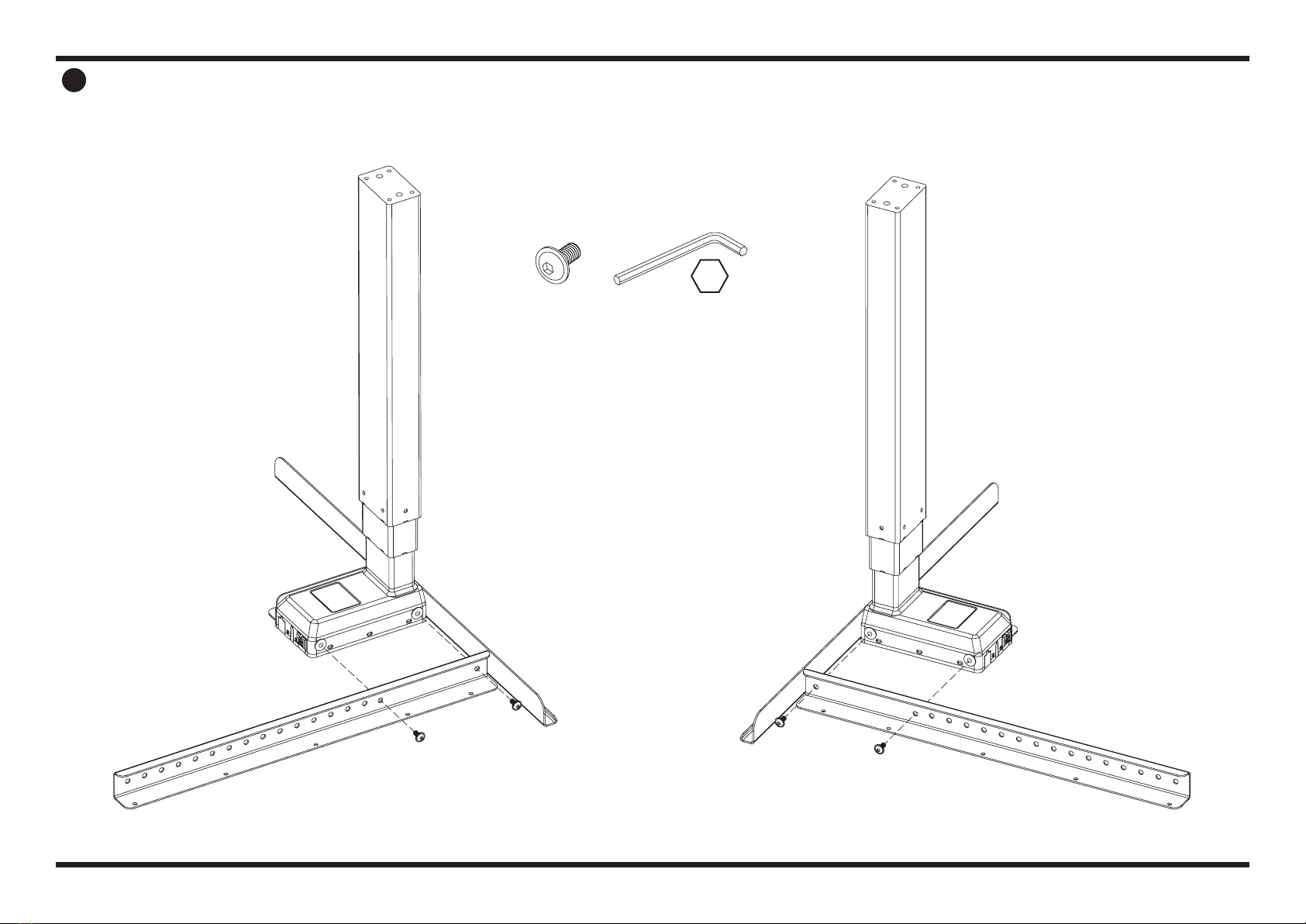
D
1INSTALL LEFT & RIGHT SIDEBARS
Attach Left & Right Sidebars (Part C & D) to
Actuators (Part A) using 8 bolts (Part J) and
supplied Allen wrench (Part V).
A
(2x)
C
NOTE: For Top Bracket types, see page 20.
J
(8x)
V
4mm
PAGE 4 OF 22
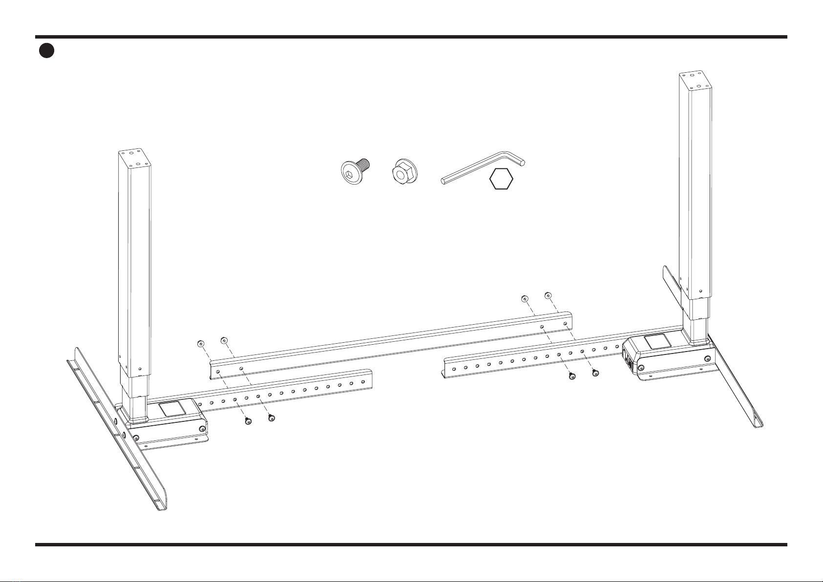
2INSTALL LEFT & RIGHT FLEX CROSSBARS
Attach Left & Right Flex Crossbars (Part E & F)
to Actuators using 4 bolts (Part J) and supplied
Allen wrench (Part V).
J
(4x)
E
F
V
4mm
PAGE 5 OF 22
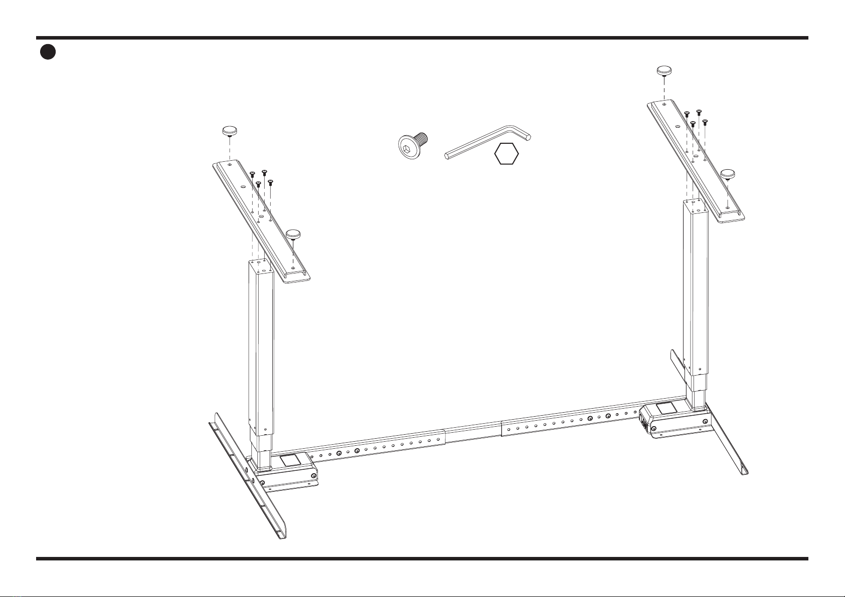
3INSTALL CENTER FLEX CROSSBAR
J
(4x)
K
(4x)
G
Install the Center Flex Crossbar (Part G)
onto the Left and Right Crossbars using
4 bolts (Part J), 4 nuts (Part K), and supplied
Allen wrench (Part V).
NOTE: For Flex Crossbar sizes and sku, see page 7.
V
4mm
PAGE 6 OF 22
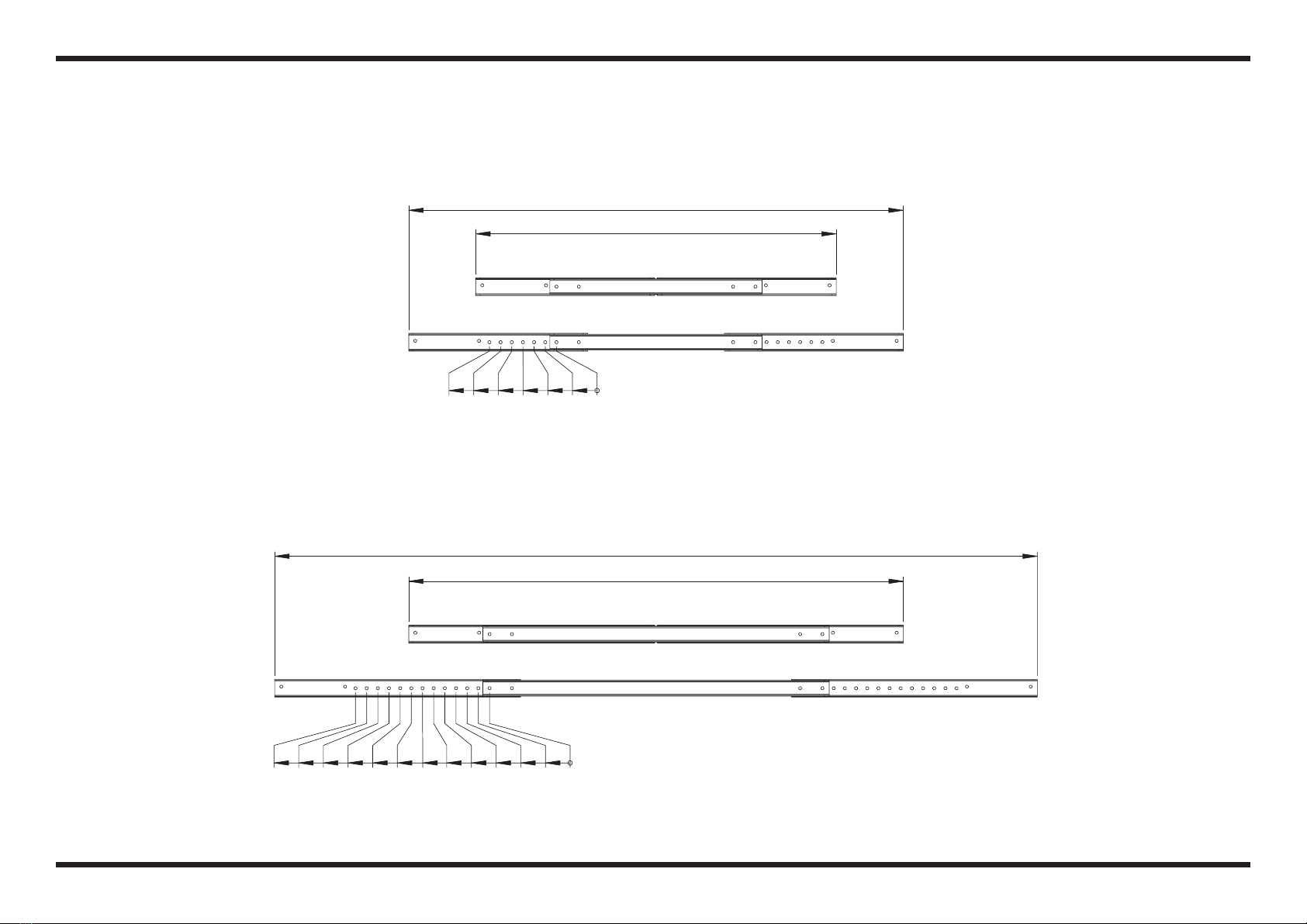
FLEX CROSSBAR OVERVIEW
72"
70"
68"
66"
64"
62"
60"
58"
56"
54"
52"
50"
48"
38"
46"
44"
42"
40"
48"
36"
For 48" surfaces
For 72" surfaces
For 48" surfaces
For 36" surfaces
A-Flex Crossbar: Surfaces 36" - 48" (914.4mm-1219.2mm)
66730610
B-Flex Crossbar: Surfaces 48" - 72" [1219.2mm-1828.8mm]
66750610
PAGE 7 OF 22
4INSTALL FEET AND GLIDERS
Place Feet (Part H) on top of
Actuators so that the Actuator fits
into the top side of the Feet.
Secure Feet to Actuators using
8 bolts (Part J) and supplied Allen
wrench (Part V).
Screw in Gliders (Part I) to be hand
tight. You can later adjust and level
your desk by screwing/unscrewing
these pads as needed.
I
(4x)
H
(2x)
J
(8x)
V
4mm
PAGE 8 OF 22
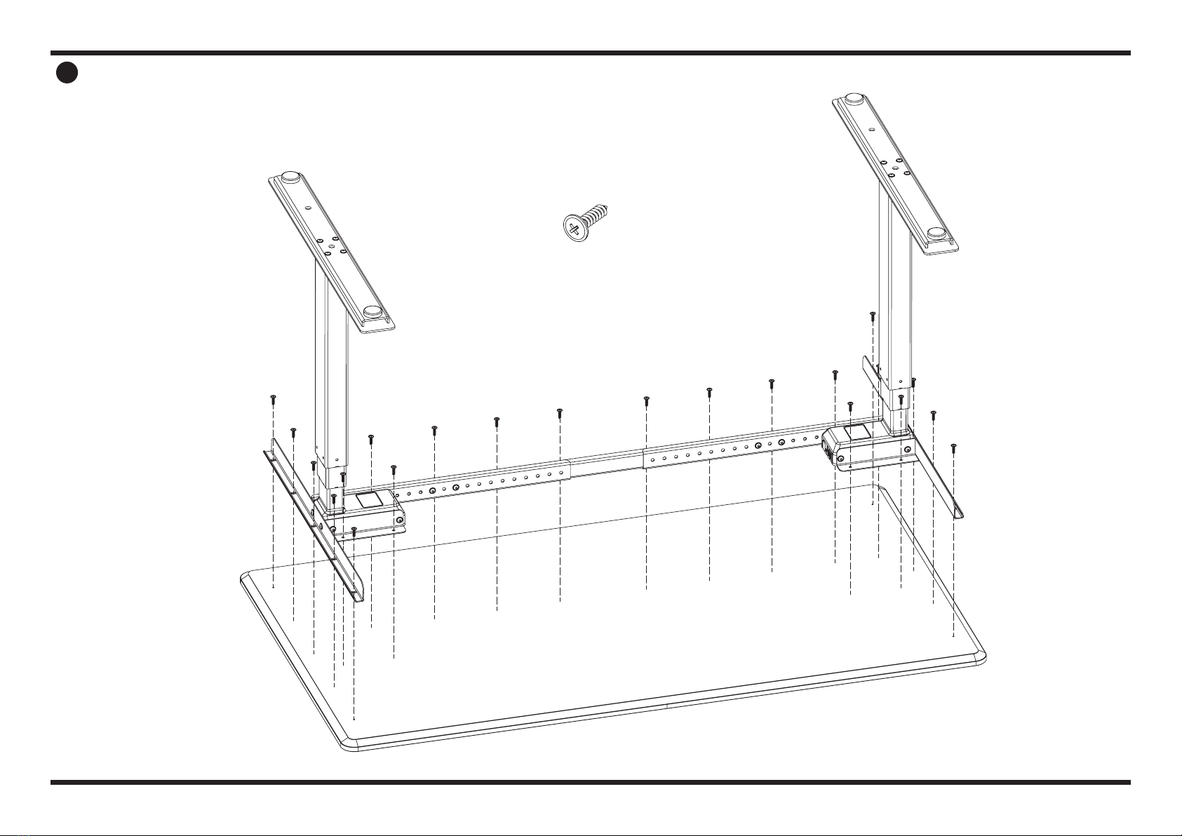
5INSTALL WORKSURFACE
Attach the base assembly to the
underside of the worksurface using
24 wood screws (Part L).
L
(24x)
PAGE 9 OF 22
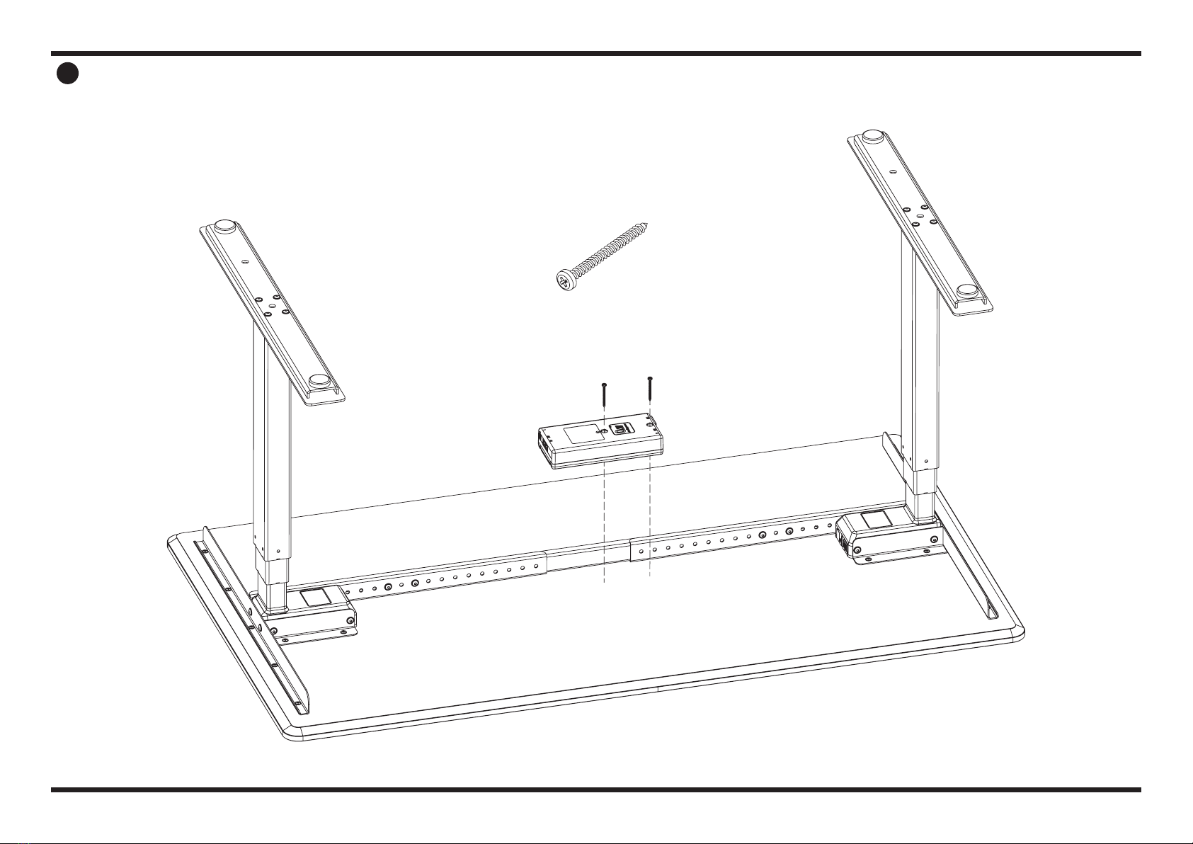
6INSTALL CONTROL BOX
Attach the Control Box (Part B) to the underside of the
worksurface using 2 wood screws (Part M).
M
(2x)
B
PAGE 10 OF 22
7a INSTALL SWITCH
Attach the switch to either the 45° Switch
Bracket (Part O) or the 90° Switch Bracket
(Part P).
With the Switch attached to the bracket,
place the Switch on the underside of the
worksurface and attach using 2 wood
screws (Part N).
O or P
Q
Q Q
45° Switch Bracket 90° Switch Bracket
O P
N
(2x)
PAGE 11 OF 22
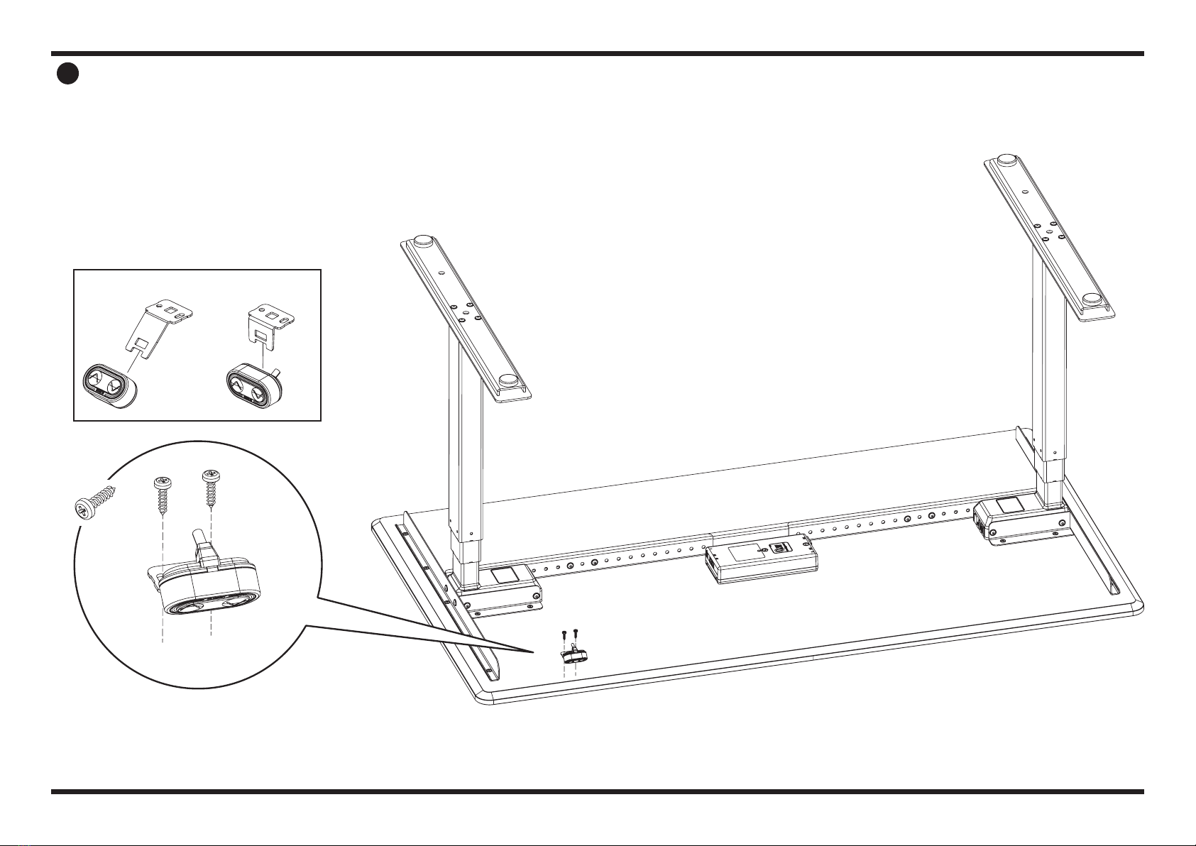
7b INSTALL PERSONAL HEALTH TRACKER SWITCH (SOLD SEPARATELY)
Place the Health Tracker Switch on the underside of the worksurface,
and place the Switch Cover onto the Switch so that the two extruded
cylinders line up with the mounting points.
NOTE: The cord should be managed through the slot in the back
of the cover to avoid crimping when finalizing attachment.
Attach the Health Tracker Switch and the Switch Cover to the
underside of the worksurface using the 4 x 30mm screws (R011504).
4 x 30mm Screw
(2x)
Switch Cover
Switch
PAGE 12 OF 22

8PLUG IN POWER & SWITCH COMPONENTS
NOTE: Only apply power when all connections are done.
Q
T
S
R
U
N
B
Begin by plugging the Switch (Part Q) into the Control Box (Part B).
Plug Motor Cables (Part R & S) into the Actuators and plug other end into Control Box (Part B).
Ensure enough Power Cable (Part T) is available to reach your work space’s plug or outlet.
Use “U-shape” strain relief channel in base of Control Box (Part B) or Wire Clip (Part U) to ensure
any strain on the Power Cable (Part T) will not unplug connection in Control Box (Part B).
Manage excess slack in cables with 4 x 16mm wood screws (Part N) and Wire Clips (Part U).
Make loops with excess cable and secure on either side with clips.
NOTE: Do not secure more than two lengths of cable in each Wire Clip (Part U).
Take care to not damage or crimp the cables in the Wire Clips (Part U).
PAGE 13 OF 22
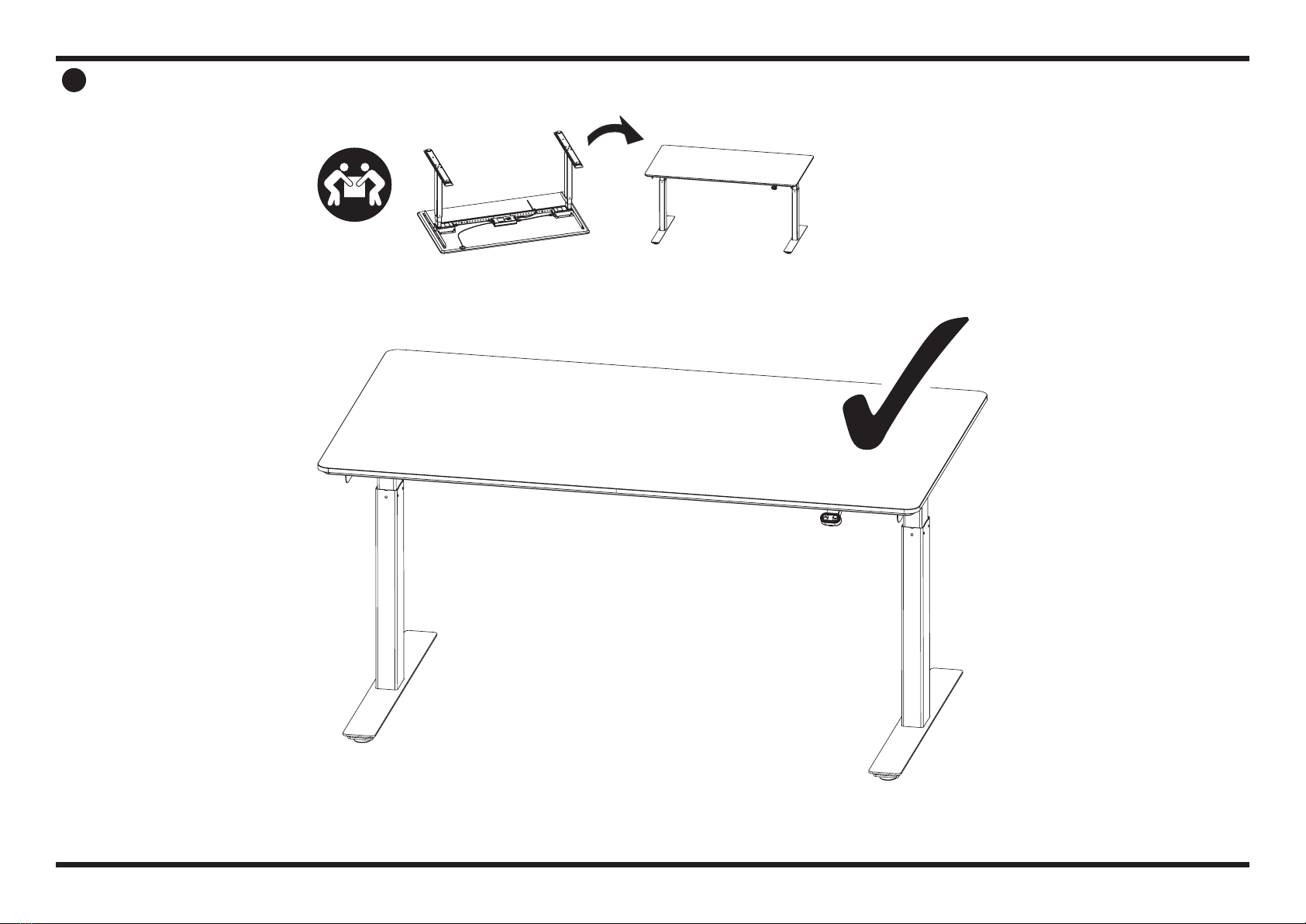
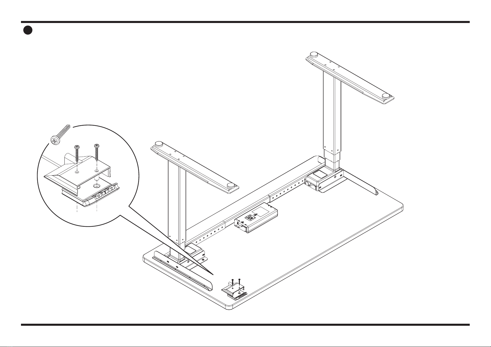
9FLIP THE DESK UPRIGHT
We recommend using two people to
safely flip the completed desk onto
its feet.
Plug in the desk and ensure Switch
is working correctly. For detailed
Switch instructions, please see
pages 15-16.
PAGE 14 OF 22
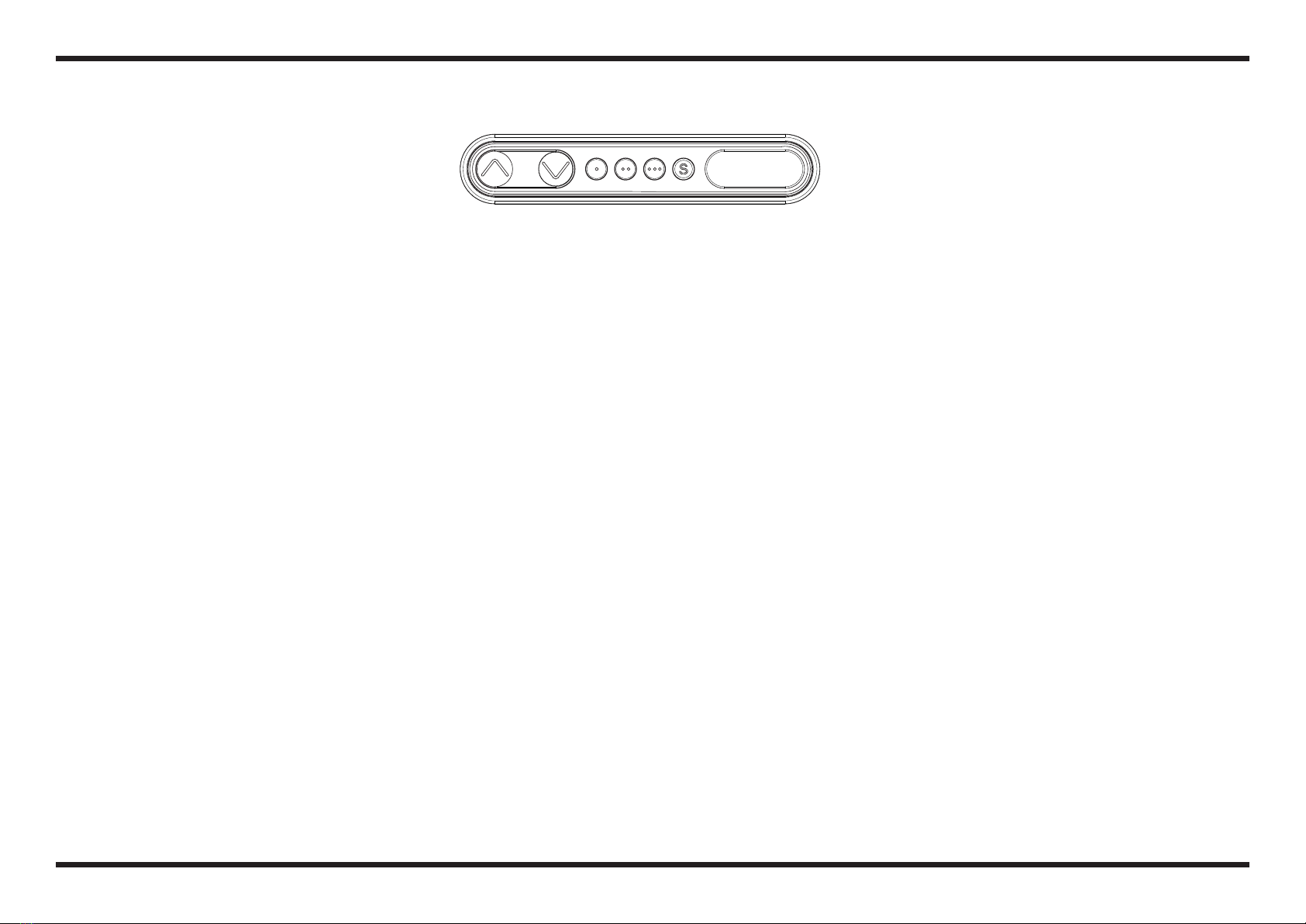
DIGITAL SWITCH OPERATIONPERFORM INITIAL RESET
Connect power cord to 120v power outlet.
INITIALIZE
The desk cannot drive up if it has not been initialized.
This is error code E01.
How to initialize:
1. Press down key and drive to the lowest position.
Hold the key until the desk stops completely.
2. Reactivate the down key and hold the key until the
desk stops completely. Now the desk can drive up.
/\ = PARALLEL UP
\/ = PARALLEL DOWN
S = STORE MEMORY
• = MEMORY 1
•• = MEMORY 2
••• = MEMORY 3
UP AND DOWN ( \/ /\ )
Just activate either the up or down button for parallel drive
and the system will drive until the button is released again
or the system reaches end position.
MEMORY
The four small buttons are used for memory drive/storing
memory.
STORE MEMORY
• Press S – button, the display will ash for 2 seconds
• Within these two seconds press one of the small buttons
with dots and the position will be stored at this button.
• The panel will acknowledge by showing “1”, “2” or “3” in
the display depending on chosen position
MEMORY DRIVE (small buttons with dots)
Press one of the memory buttons and the system will start
driving to the pre-programmed memory position.
DISPLAY FUNCTION
Shows the actual height in either cm or inch.
ADJUSTING INITIAL HEIGHT
It may be necessary to adjust the displayed height due to
dierent thicknesses of desktops etc. The DPF1C will as
standard either show 68 cm or 24.5 inch as the default
desk height.
PROCEDURE
Press /\ and \/ keys at the same time and keep them pressed
for 5 seconds. This allows the initial height to be adjusted.
Until the initial height can be adjusted, the display will
show three minuses (---) hereafter the display will revert
to showing the height. The height can then be adjusted by
either /\ or \/ until til desired height has been reached. The
system will return to normal operation (and give a short
blink) after 5 seconds of inactivity on the keys.
The feature can be disabled via conguration in which
case pressing the /\ and \/ keys at the same time will be
considered an illegal keypress.
PAGE 15 OF 22

PERSONAL HEALTH TRACKER OPERATION
/\ = PARALLEL UP
\/ = PARALLEL DOWN
= REMINDER
= BLUETOOTH®
= STORE MEMORY
TILT
TILT
UP AND DOWN
Just tilt the switch either up or down to activate parallel
drive and the system will drive until the switch has been
released or the system reaches end position.
REMINDER
To adjust the reminder interval press the bell button. A
white block on the bottom of the display will appear for
the numerical interval chosen (1 block for interval 1 etc). If
no white blocks are displayed, the reminder setting on the
switch is off.
The intervals that can be chosen from are as follows:
• Interval 1: Reminder after 55 minutes of sitting
• Interval 2: Reminder after 50 minutes of sitting
• Interval 3: Reminder after 45 minutes of sitting
The light strip will pulsate orange when it is time for the
user to switch to standing. The light strip will pulsate green
when the interval has not reached its end. After 4 hours of
no interaction with the switch, it will time out and no colored
strip will appear.
STORE MEMORY
• Press the star button shortly, and wait for the 4 memory
positions to show.
• Choose which memory position (1-4) you would like to save.
• Press and hold the star button for 2 seconds.
• The light strip on the face of the switch will blink white
two times.
• Once the light strip becomes a static white, the chosen
position with the star symbol will appear indicating the
height has been saved to that position.
• To erase all memory, hold the star button for 8 seconds
until the light strip appears red.
MEMORY DRIVE
Just tilt the switch either up or down to activate parallel
drive and the system will drive until the first stored position
in the chosen direction has been reached. To move past this
position, either continue tilting the switch or release, and tilt
in the same direction again.
BLUETOOTH®
Pressing the Bluetooth button for 2 seconds will activate
pairing mode where the light strip will pulsate blue.
Download the Desk Control App suited for your device in
App, Google Play or Windows store and pair the app and
device. The display on the DPG1C will inform about the
Bluetooth-ID of the desk, which is “DESK” followed by a
4-digit number – look for this ID in the list of “Desks nearby”.
FACTORY RESET
To reset to factory default settings, hold both the “Memory”
and “Reminder” buttons for 8 seconds. The light strip will
pulsate red 3 times, after which a countdown until the reset
will be initialized on the display.
DISPLAY FUNCTION
Shows the actual height in either cm or inch.
ADJUSTING INITIAL HEIGHT
It may be necessary to adjust the displayed height due to
dierent thicknesses of desktops etc. The DPG1C will as
standard either show 68 cm or 24.5 inch as the default
desk height.
PROCEDURE
Press and hold both the “Reminder” and the “Bluetooth”
button on the DPG1C at the same time for 5 seconds. The
height display will start to blink, at which the switch can be
tilted up or down to adjust the readout without moving the
desk. To conrm the readout, press any button or wait 10
seconds after having adjusted it.
SWITCHING BETWEEN CM AND INCH
To switch between cm and inches on the display, press
and hold both the “Memory” and “Bluetooth” button for 5
seconds until the current measurement units blink. Just
tilt the switch to change the units, and press any button to
conrm or wait 10 seconds after having adjusted it.
PAGE 16 OF 22

TROUBLE SHOOTING AND DIAGNOSIS
The included electric height adjustable table that is not
working properly can be evaluated to determine why the
table isn’t functioning.
Take note of how the table is malfunctioning and any error
codes that are displayed on the digital readout switch.
Make sure to check all cables and power cord connections.
Unplug everything (all control cables from control box and
legs, power cord, and control switch from control box),
allow the table to sit for 10 seconds, and then reattach
all connections. While reattaching all connections, check
female ports to ensure all “six” pins in each port are straight
and not bent.
RESET THE WORKSTATION
1. Press the down button and hold until the desk is
fully lowered.
2. Press the down button and release, then immediately
press and hold the down button for 5-6 seconds looking
for slight movement down and then back up. Reset is
complete.
3. Press the up button and desk will function normally.
Reset may need to be performed up to three times in
succession before positive movement is seen.
COLLISION DETECTION
Collision Detection is designed to mitigate hardware
damage if a hard collision between the table and another
surface is to occur. This is done by detecting a predened
dierence in current consumption by the channels on the
control box. If this takes place, the legs are brought to a
halt and run in the reverse direction for about 1.97" (50mm)
without having to hit the switch, to avoid any damage to the
components of the table.
FORCE REQUIRED TO ACTIVATE ANTI-COLLISION
Upwards: 44 lbs (20 kg)
Downwards: 88 lbs (40 kg + load on desk and desk itself)
Please Note: Force required to activate is based on a
sudden concentrated load directly to the leg actuator. Leg
position, amount of surface cantilever, size of application,
and amount of overall loading will aect the sensitivity and
amount of force required to activate.
SITUATIONS IN WHICH ANTI-COLLISION
DOES NOT WORK:
• If the collision happens when initializing the table.
• If the collision happens within 1 second of activation, or
after the control box has been released.
• If the collision happens between the oor and the table
and the load on the desk + the weight of the legs are
lower than 88 lbs (40kg).
• If the collision happens for an extended period of time,
like colliding with a soft object.
STANDARD ERROR CODES
ERROR DESCRIPTION ACTION
EOl
Desk has an unknown
position and needs to
be reset
Reset Desk
E23 Channel 1 is detected
missing
Check all cable
connections associated
with port 1
E24 Channel 2 is detected
missing
Check all cable
connections associated
with port 2
E25 Channel 3 is detected
missing
Check all cable
connections associated
with port 3
E59 Safety limit switch
activated on channel 1
Check for obstruction,
or binding due to
frame assembly
E60 Safety limit switch
activated on channel 2
Check for obstruction,
or binding due to
frame assembly
E61 Safety limit switch
activated on channel 3
Check for obstruction,
or binding due to
frame assembly
408 437 8770
?
PAGE 17 OF 22

SPECIFICATIONS
BASE:
• Complete 2-leg, electric adjustable frame
• Feet Options:
- M - Medium Cantilevered
21.56" (548mm) Advance L-Model
- V22 - Medium Cantilevered
21.56" (548mm) Entry L-Model
- L - Large Cantilevered
27.56" (700mm) Advance L-Model
- T - Large Centered
27.56" (700mm) Advance T-Model
- V28T - Large Centered
27.56" (700mm) Entry T-Model
• Under-Frame Options:
- 15.76" (400mm) Cantilevered under-frame
- 26.77" (680mm) Centered under-frame
- 11.81" (300mm) Bi-level under-frame
• Flex Frame, three-piece, adjustable construction
• Complete frame outside dimension, adjustment range:
34" - 88" (863.6mm - 2235.2mm)
- A-FLEX range = 34" - 46" (863.6mm - 1168.4mm)
- B-FLEX range = 46" - 70" (1168.4mm - 1778.0mm)
- C-FLEX range = 64" - 88" (1625.6mm - 2235.2mm)
- Frames adjust in 1" (25.4mm) increments
• Switch Options:
- Simple Up/down control switch (UD)
- Digital programmable control switch with readout,
3x preset, auto drive (DS)
- Personal Heath Tracker control switch (PH)
• Finish – Powder coated steel
• Frame Height Range (without desktop):
– SX 3-Stage base: 21.1" - 47.6" (535.9mm - 1209.0mm)
– SE 2-Stage base: 26.0" - 44.5" (660.4mm - 1130.3mm)
• Operation: Electric
• Weight Capacity: 350lbs (159kg)
(frame only, without desktop)
• Adjustment Speed: 1.5" (38.0mm)/second
WORKSURFACE / DESKTOP SIZE RANGE:
Dimensions:
• Width: 36.0" - 96.0" (914.4mm - 2438.4mm)
• Depth: 24.0" - 30.0" (558.8mm - 914.4mm)
• Thickness: Minimum 1.0" (25.0mm)
USAGE:
• Two parallel drive leg actuators (DL6000XN0665518) and
1x AC to DC control box (CBD6SP00020A-109)
• Duty cycle: 10% ~ 6 min. Per hour or 2 min.
Use at full load.
• Ambient temperature: +50°F to 104°F (+10°C to 40°C)
• Storage and transportation temperature: 14°F to 158°F
(-10°C to +70°C)
PAGE 18 OF 22
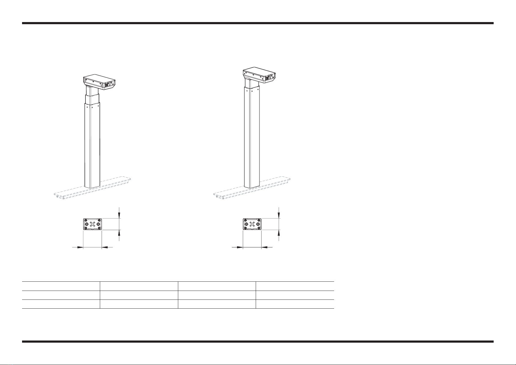
ACTUATOR STANDARD OVERVIEW
3.14"
(80mm)
1.96"
(50mm)
3.14"
(80mm)
1.96"
(50mm)
ACTUATOR TYPE BLACK WHITE SILVER
SX 63020610-1 63020604-1 63020630-1
SE 66020710-1 66020704-1 66020730-1
SX SE
PAGE 19 OF 22

TOP BRACKET OVERVIEW
Cantilevered under-frame
15.76" (400mm)
R063 524/534
Bi-level under-frame
11.81" (300mm)
R063 503/513
Centered under-frame
26.77" (680mm)
R063 507/517
PAGE 20 OF 22
This manual suits for next models
1
Table of contents
Other HAT collective Indoor Furnishing manuals

Popular Indoor Furnishing manuals by other brands

Regency
Regency LWMS3015 Assembly instructions

Furniture of America
Furniture of America CM7751C Assembly instructions

Safavieh Furniture
Safavieh Furniture Estella CNS5731 manual

PLACES OF STYLE
PLACES OF STYLE Ovalfuss Assembly instruction

Trasman
Trasman 1138 Bo1 Assembly manual

Costway
Costway JV10856 manual


