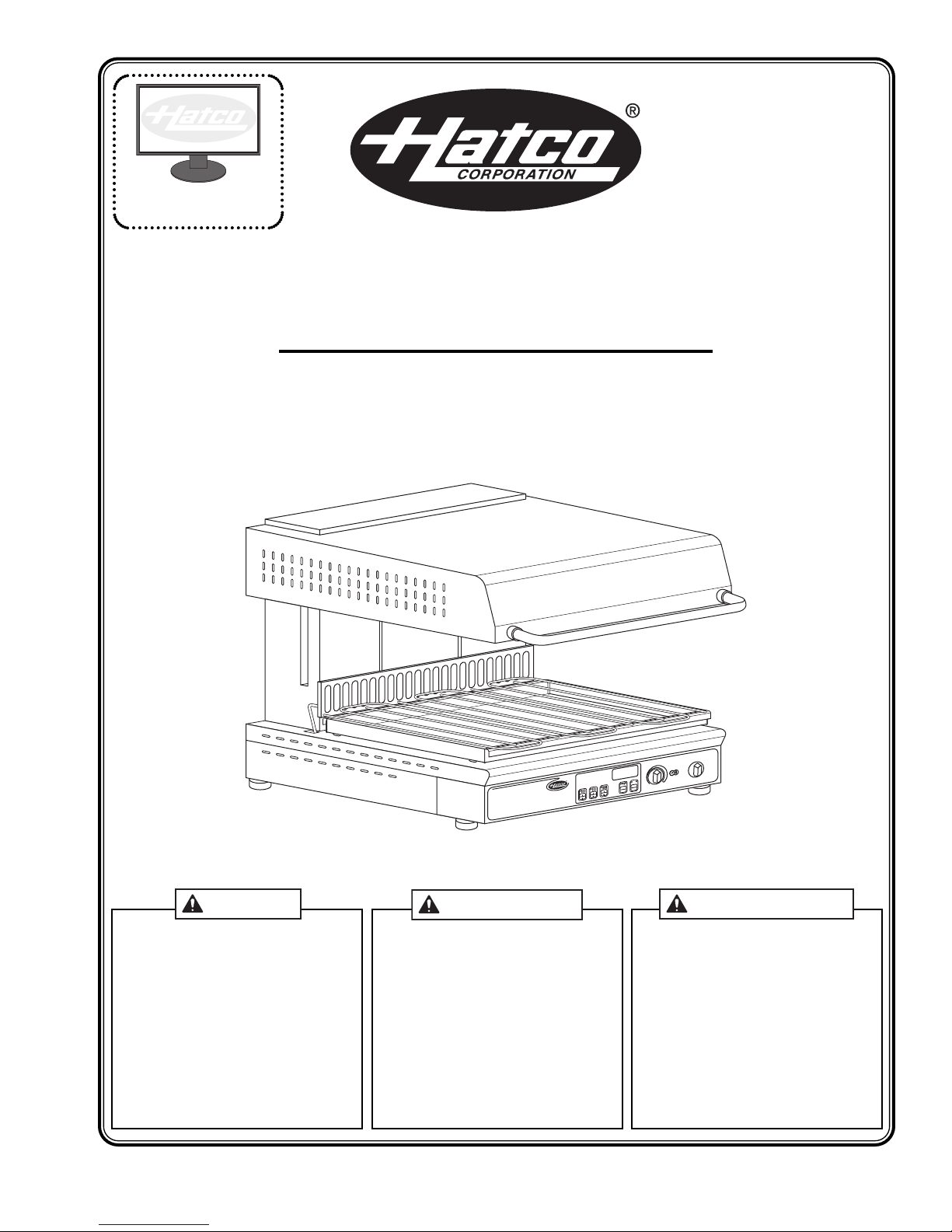
IMPORTANT SAFETY INFORMATION
Form No. QTSM-0213 3
FIRE HAZARD:
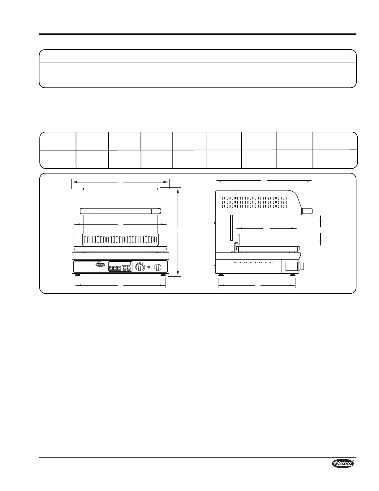
• To reduce the risk of fire, the appliance is to be installed
in non-combustible surroundings only, with no
combustible material within 46 cm (18″) of the sides,
front, or rear of the appliance or within 102 cm (40″)
above the appliance. The appliance is to be mounted
on floors of non-combustible construction with non-
combustible flooring and surface finish and with no
combustible material against the underside, or on non-
combustible slabs or arches that have no combustible
material against the underside. Such construction shall
in all cases extend not less than 30 cm (12″) beyond the
equipment on all sides.
• Locate the unit a minimum of 51 mm (2″) from any
walls. If safe distances are not maintained,
discoloration or combustion could occur.
• Do not obstruct air ventilation openings on outer
housing of unit. Unit combustion or malfunction may
occur.
• Do not place anything on top of unit.
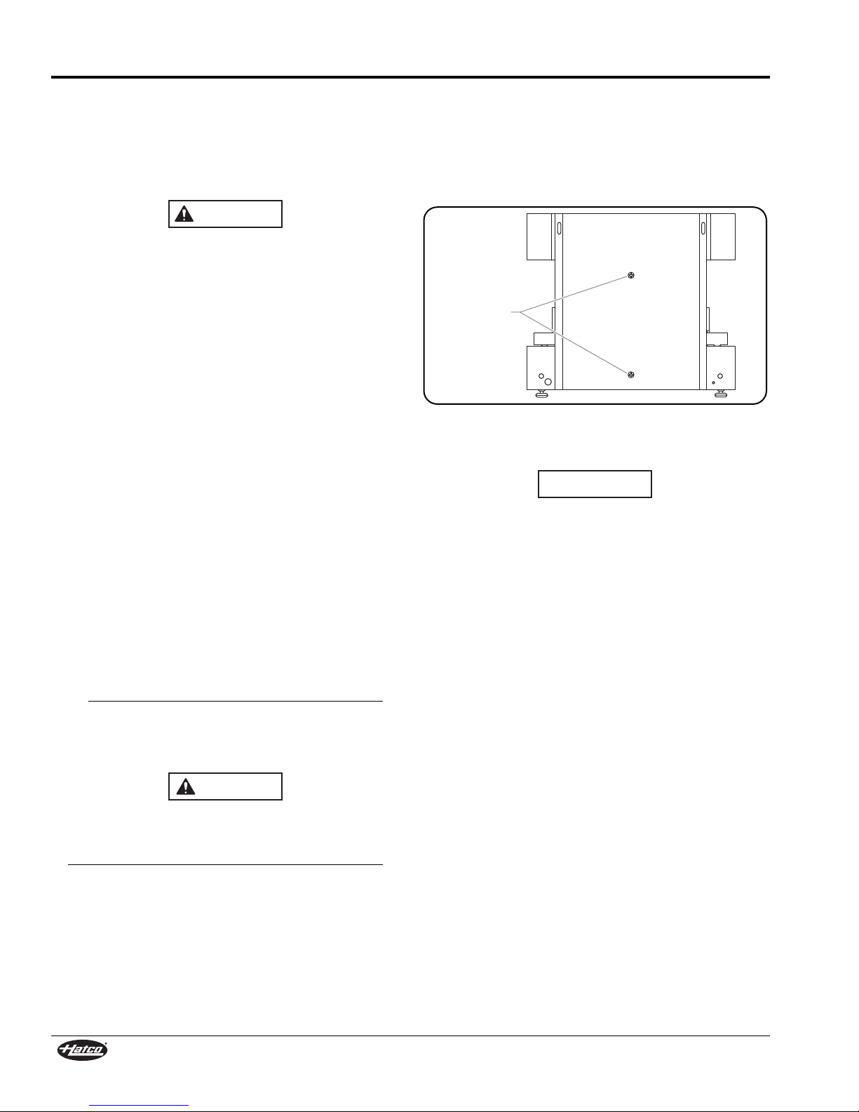
For wall mounting, use special wall mount bracket provid-
ed with unit only. Secure wall mount bracket to a solid, non-
combustible surface using appropriate hardware for mount-
ing surface and weight of unit.
Make sure all operators have been instructed on the safe and
proper use of the unit.
This unit is not intended for use by children or persons with
reduced physical, sensory, or mental capabilities. Ensure
proper supervision of children and keep them away from the
unit.
This unit has no “user-serviceable” parts. If service is
required on this unit, contact an Authorized Hatco Service
Agent or contact the Hatco Service Department at
414-671-6350; fax 414-671-3976.
BURN HAZARD:
• Some exterior surfaces on unit will get hot. Use caution
when touching these areas.
• Plate/tray will be very hot upon removal—use oven mitt,
protective clothing, or pan gripper to remove.
Make sure electrical supply matches the voltage and
frequency rating on the specification plate. Incorrect
electrical supply may damage unit.
Locate unit at proper counter height in an area that is con-
venient for use. Location should be level to prevent unit or
its contents from falling accidentally and strong enough to
support the weight of the unit and contents.
Do not place anything on top of unit; doing so may subject
personnel to injury or damage unit.
ELECTRIC SHOC HAZARD:
• Unit must be installed by a qualified electrician.
Installation must conform to all local electrical codes.
Installation by unqualified personnel will void unit
warranty and may lead to electric shock or burn, as well
as damage to unit and/or its surroundings.
• Units supplied without an electrical cord and plug
require field installation of proper cord and plug or a
hardwired connection to on-site electrical system.
Connection must be properly grounded and of correct
voltage, size, and configuration for electrical
specifications of unit. Contact a qualified electrician to
determine and install proper electrical connection.
• When installing a hardwired unit, a 3-pole or 4-pole
disconnect switch (depending on unit) must be
installed between unit and main electrical supply. The
switch must be rated properly and have contacts with
a minimum opening distance of 3 mm (1/8″).
• Unit must be connected to an equipotential system that
complies with the latest electrical standards.
• Turn OFF power switch, unplug power cord/turn off
power at circuit breaker, and allow unit to cool before
performing any cleaning, adjustments, or maintenance.
• Unit is not weatherproof. Locate unit indoors where
ambient air temperature is a minimum of 21°C (70°F)
and a maximum of 45°C (113°F).
• Do not install unit above a steam table or other steam
generating appliance.
• DO NOT submerge or saturate with water. Unit is not
waterproof. Do not operate if unit has been submerged
or saturated with water.
• Do not steam clean or use excessive water on unit.
• This unit is not “jet-proof” construction. Do not use jet-
clean spray to clean this unit.
• Do not clean unit when it is energized or hot.
• This unit must be serviced by qualified personnel only.
Service by unqualified personnel may lead to electric
shock or burn.
• Use only Genuine Hatco Replacement Parts when
service is required. Failure to use Genuine Hatco
Replacement Parts will void all warranties and may
subject operators of the equipment to hazardous
electrical voltage, resulting in electrical shock or burn.
Genuine Hatco Replacement Parts are specified to
operate safely in the environments in which they are
used. Some aftermarket or generic replacement parts
do not have the characteristics that will allow them to
operate safely in Hatco equipment.
EXPLOSION HAZARD: Do not store or use gasoline or
other flammable vapors or liquids in the vicinity of this or
any other appliance.
Read the following important safety information before using this equipment to avoid
serious injury or death and to avoid damage to equipment or property.