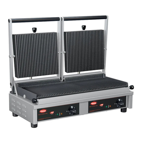
Hatco TMS Series User manual

© 2015 Hatco Corporation
THERM-MAX
Salamander
TMS Series
Installation and Operating Manual
For and non- Models
P/N07.04.582.00
Salamander
Modelreeksen TMS
Handleiding voor Installatie en Bediening
P 57
Registreer online!
Salamandra
Series TMS
Manual de Instalación y Operación
P 24
¡Regístrese en línea!
Fornello portatilei
Serie TMS
Manuale per l'installazione e l'uso
P 46
Registratevi online!
Salamander
Serien TMS
Installations- und Bedienungshandbuch
P 13
Registrieren Sie sich online!
Salamander
Séries TMS
Manuel d'installation et d'utilisation
P 35
S'inscrire en ligne!
Register Online!
(see page 2)
hatcocorp.com
Original Instructions
Originalanleitung
Instrucciones originales
Instructions originales
Istruzioni originali
Vertaling van de
originele instructies

Form No. TMSCEM-0615
2
CONTENTS
Safety information that appears in this manual is identified by
the following signal word panels:
WARNIN indicates a hazardous situation which, if not
avoided, could result in death or serious injury.
CAUTION indicates a hazardous situation which, if not
avoided, could result in minor or moderate injury.
NOTICE is used to address practices not related to personal
injury.
WARNING
NOTICE
CAUTION
INTRODUCTION
Hatco’s THERM-MAX Salamanders are specially-designed for
cooking, grilling, reheating, and keeping foods hot. Their
unparalleled startup speed is a direct result of Hatco’s patented
“instant on” heating elements located in the upper housing of
each salamander. The two pairs of independently-controlled
heating elements provide for the benefits of flexibility and
energy conservation. Reduced transfer of heat to the
surrounding area and a versatile hold function on certain
models make the THERM-MAX Salamander energy efficient
and easy to operate.
Hatco THERM-MAX Salamanders are products of extensive
research and field testing. The materials used were selected
for maximum durability, attractive appearance, and optimum
performance. Every unit is inspected and tested thoroughly
prior to shipment.
This manual provides the installation, safety, and operating
instructions for THERM-MAX Salamanders. Hatco
recommends all installation, operating, and safety instructions
appearing in this manual be read prior to installation or
operation of a unit.
Important Owner Information ..............................................2
Introduction...........................................................................2
Important Safety Information...............................................3
Model Description.................................................................4
Model Designation................................................................4
Specifications........................................................................5
Electrical Rating Chart ........................................................5
Dimensions .........................................................................5
Installation .............................................................................6
eneral ...............................................................................6
Countertop Installation ........................................................6
Wall Installation ...................................................................7
Electrical Connections.........................................................7
Operation...............................................................................8
eneral ...............................................................................8
Control Panel ......................................................................8
Operating the Salamander..................................................9
Maintenance ........................................................................10
eneral .............................................................................10
Daily Cleaning...................................................................10
Troubleshooting uide.......................................................11
International Limited Warranty..........................................12
Service Information ............................................................12
IMPORTANT OWNER INFORMATION
Record the model number, serial number, voltage, and
purchase date of the unit in the spaces below (located on the
side of the unit near the power inlet area). Please have this
information available when calling Hatco for service assistance.
Model No. ________________________________________
Serial No. ________________________________________
Voltage __________________________________________
Date of Purchase __________________________________
Register your unit!
Completing online warranty registration will prevent delay in
obtaining warranty coverage. Access the Hatco website at
www.hatcocorp.com, select the Parts & Service pull-down
menu, and click on “Warranty Registration”.
Business
Hours: 7:00 AM to 5:00 PM Central Standard Time (C.S.T.)
(Summer Hours: June to September—
7:00 AM to 5:00 PM C.S.T.
Monday through Thursday
7:00 AM to 4:00 PM C.S.T. Friday)
Telephone: (414) 671-6350
E-mail: part[email protected]
Fax: (414) 671-3976 (Parts and Service)
Additional information can be found by visiting our web site at
www.hatcocorp.com.
Correct Disposal of this Product
This marking indicates that this product and its electronic
components should not be disposed of with other
commercial waste. To prevent possible harm to the
environment or human health from uncontrolled waste
disposal, recycle responsibly to promote the sustainable
reuse of material resources. To dispose of product and its
electronic components, contact supplier where product
was purchased for environmentally safe recycling.

IMPORTANT SAFETY INFORMATION
FIRE HAZARD:
• Install unit on and around non-combustible surfaces
with non-combustible construction only. Ensure surface
construction has no combustible material against
underside. In all cases, such construction shall extend at
least 305 mm (12″) beyond equipment on all sides.
• Locate unit a minimum of 51 mm (2″) from any walls. If
safe distances are not maintained, discoloration or
combustion could occur.
• Do not obstruct air intake openings or air exhaust
openings on outer housing of unit. Unit combustion or
malfunction may occur.
• Do not place anything on top of unit.
For wall mounting, use special wall mount bracket
provided with unit only. Secure wall mount bracket to a
solid, non-combustible surface using appropriate hardware
for mounting surface and weight of unit.
Make sure all operators have been instructed on the safe
and proper use of the unit.
This unit is not intended for use by children or persons
with reduced physical, sensory, or mental capabilities.
Ensure proper supervision of children and keep them away
from the unit.
This unit has no “user-serviceable” parts. If service is
required on this unit, contact an Authorized Hatco Service
Agent or contact the Hatco Service Department at
414-671-6350; fax 414-671-3976.
BURN HAZARD:
• Some exterior surfaces on the unit will get hot. Use
caution when touching these areas.
• Plate/tray will be very hot upon removal — use oven
mitt, protective clothing, or pan gripper to remove.
Locate unit at proper counter height in an area that is
convenient for use. Location should be level to prevent unit
or its contents from falling accidentally and strong enough
to support the weight of the unit and contents.
Do not place anything on top of unit; doing so may subject
personnel to injury or damage unit.
Units are voltage-specific. Refer to specification label for
electrical requirements before beginning installation.
Do not lock ON timer knob. Unit has instant-on heating
elements designed to reach cooking temperatures quickly.
Locking ON timer knob will increase energy consumption
and may shorten life of heating elements.
Use non-abrasive cleaners and cloths only. Abrasive
cleaners and cloths could scratch finish of unit, marring its
appearance and making it susceptible to soil accumulation.
Clean unit daily to avoid malfunctions and maintain
sanitary operation.
NOTICE
CAUTION
WARNING
ELECTRIC SHOCK HAZARD:
• Unit must be installed by a qualified electrician.
Installation must conform to all local electrical codes.
Installation by unqualified personnel will void unit
warranty and may lead to electric shock or burn, as well
as damage to unit and/or its surroundings.
• Units supplied without an electrical plug require field
installation of proper plug. Plug must be properly
grounded and of correct voltage, size, and
configuration for electrical specifications of unit.
Contact a qualified electrician to determine and install
proper electrical plug.
• Units supplied without an electrical cord and plug
require field installation of proper cord and plug or a
hardwired connection to on-site electrical system.
Connection must be properly grounded and of correct
voltage, size, and configuration for electrical
specifications of unit. Contact a qualified electrician to
determine and install proper electrical connection.
• When installing a hardwired unit, a 2-pole or 3-pole
switch (depending on unit) must be installed between
unit and main electrical supply. The switch must be
rated properly and have contacts with a minimum
opening distance of 3 mm (1/8″).
• Turn OFF power switch, unplug power cord/turn off
power at circuit breaker, and allow unit to cool before
performing any cleaning, adjustments, or maintenance.
• DO NOT submerge or saturate with water. Unit is not
waterproof. Do not operate if unit has been submerged
or saturated with water.
• Unit is not weatherproof. Locate unit indoors where
ambient air temperature is a minimum of 21°C (70°F)
and a maximum of 29°C (85°F).
• Do not steam clean or use excessive water on unit.
• This unit is not “jet-proof” construction. Do not use jet-
clean spray to clean this unit.
• Do not pull unit by power cord.
• Discontinue use if power cord is frayed or worn.
• Do not attempt to repair or replace a damaged power
cord. Cord must be replaced by Hatco, an Authorized
Hatco Service Agent, or a person with similar
qualifications.
• Do not clean unit when it is energized or hot.
• This unit must be serviced by qualified personnel only.
Service by unqualified personnel may lead to electric
shock or burn.
• Use only enuine Hatco Replacement Parts when
service is required. Failure to use enuine Hatco
Replacement Parts will void all warranties and may
subject operators of the equipment to hazardous
electrical voltage, resulting in electrical shock or burn.
enuine Hatco Replacement Parts are specified to
operate safely in the environments in which they are
used. Some aftermarket or generic replacement parts
do not have the characteristics that will allow them to
operate safely in Hatco equipment.
WARNING
Form No. TMSCEM-0615 3
Read the following important safety information before using this equipment to avoid serious
injury or death and to avoid damage to equipment or property.

MODEL DESCRIPTION
All Models
Hatco’s THERM-MAX Salamander is specially-designed for
versatility in the kitchen with the capabilities to cook, grill,
reheat, and keep foods hot. The salamander is constructed of
stainless steel for easy cleaning and durability. The four high-
powered heating elements are ready for use within 8 seconds.
Each pair of heating elements can be controlled independently
or together using the heating mode selector and timer knob
located on the control panel. The heating elements are
strategically positioned inside the moveable upper housing to
reduce the transfer of heat to the surrounding area. The HOLD
function on TMS-1H models is ideal for keeping foods hot or
reheating foods. A removeable cooking grate and drip tray
allows for easy cleanup. The unique features and flexibility of
the THERM-MAX Salamander make it easy to operate, energy
efficient, and highly functional in any kitchen.
Model TMS-1H
Upper
Housing
Timer Knob
Cooking
Grate
Drip
Tray
Height
Gauge
Heating Mode
Selector
MODEL DESI NATION
T M S - 1 H
THERM-MAX
Salamander Capacity = Full-Size
Gastronorm Pan
H = COOK and HOLD Functions
No Character = COOK Function Only
Model Designation
4Form No. TMSCEM-0615

Model Voltage Hertz Phase Watts Amps Shipping Weight
TMS-1H 230 50/60 1 4000 17.4 72 kg (159 lbs.)
TMS-1 230 50/60 1 4000 17.4 72 kg (159 lbs.)
230/400 50/60 3 4000 8.7 72 kg (159 lbs.)
200 50/60 3 4000 13.7 72 kg (159 lbs.)
Model Width
(A)
Depth
(B)
Height
(C)
Footprint
Width (D)
Footprint
Depth (E)
Cooking
Width (F)
Cooking
Depth ( )
Cooking
Height (H)
TMS-1H and
TMS-1 600 mm
(23-5/8″)
510 mm
(20-1/8″)
546 mm
(21-1/2″)
520 mm
(20-1/2″)
380 mm
(15″)
540 mm
(21-1/4″)
365 mm
(14-5/16″)
50 to 212 mm
(2″ to 8-1/4″)
SPECIFICATIONS
Electrical Rating Chart
NOTE: Shipping weight includes packaging.
Dimensions
Form No. TMSCEM-0615 5
Front View Side View
A
FFF
D E
G
C
H
B

INSTALLATION
6Form No. TMSCEM-0615
eneral
THERM-MAX Salamanders are shipped with most components
pre-assembled. Care should be taken when unpacking the
shipping carton to avoid damage to the unit and the
components enclosed. The salamander can be placed on a
countertop or mounted to a brick or cement wall. The following
installation instructions must be performed before operating the
salamander.
ELECTRIC SHOCK HAZARD:
• Unit must be installed by a qualified electrician.
Installation must conform to all local electrical codes.
Installation by unqualified personnel will void unit
warranty and may lead to electric shock or burn, as well
as damage to unit and/or its surroundings.
• Unit is not weatherproof. Locate unit indoors where
ambient air temperature is a minimum of 21°C (70°F)
and a maximum of 29°C (85°F).
FIRE HAZARD:
• Install unit on and around non-combustible surfaces
with non-combustible construction only. Ensure
surface construction has no combustible material
against underside. In all cases, such construction
shall extend at least 305 mm (12″) beyond equipment
on all sides.
• Locate unit a minimum of 51 mm (2″) from any walls. If
safe distances are not maintained, discoloration or
combustion could occur.
• Do not obstruct air intake openings or air exhaust
openings on outer housing of unit. Unit combustion or
malfunction may occur.
• Do not place anything on top of unit.
For wall mounting, use special wall mount bracket
provided with unit only. Secure wall mount bracket to a
solid, non-combustible surface using appropriate hardware
for mounting surface and weight of unit.
Locate unit at proper counter height in an area that is
convenient for use. Location should be level to prevent unit
or its contents from falling accidentally and strong enough
to support the weight of the unit and contents.
Do not place anything on top of unit; doing so may subject
personnel to injury or damage unit.
NOTE: A qualified person must check possi le placements of
the salamander to ensure that the proper electrical
supply line is availa le.
1. Remove the unit from the shipping carton.
NOTE: To prevent delay in o taining warranty coverage,
complete online warranty registration. See the
IMPORTANT OWNER INFORMATION section for details.
2. Remove tape and protective packaging from all surfaces
of unit.
3. Clean the unit thoroughly to remove all protective industrial
grease. NOTICE: Use non-abrasive cleaners and cloths
only.
WARNING
CAUTION
4. Remove the transport locking screw used to secure the
upper housing during shipping. Discard the screw.
Transport Locking Screw
Countertop Installation
1. Place the unit in the desired location.
• Locate the unit directly underneath an exhaust hood if
possible. This will ensure total suction of steam
produced during cooking.
• Make sure the unit is at the proper height in an area
convenient for use.
• Make sure the countertop is level and strong enough to
support the weight of the unit and food product.
• Make sure all the feet on the bottom of the unit are
positioned securely on the countertop with a minimum
of 51 mm (2″) between the unit and any wall.
Minimum Distance Requirement
2. Level the unit by turning the leveling feet on each leg, if
necessary. When looking at the bottom of the unit, turning
the feet counterclockwise will lengthen the legs, and turning
the feet clockwise will shorten the legs.
3. Have a qualified electrician perform the necessary electrical
connections (refer to “Electrical Connections” in this section
for additional information).
Transport Locking
Screw
Wall
Countertop
51 mm (2″)

Form No. TMSCEM-0615 7
INSTALLATION
Wall Installation
1. Install the wall mount bracket provided with the unit onto a
solid, non-combustible surface using the appropriate
fasteners. There are five mounting holes on the wall mount
bracket.
• Make sure the fasteners are appropriate for the
installation surface and the weight of the unit.
• Locate the unit directly underneath an exhaust hood if
possible. This will ensure total suction of steam
produced during cooking.
• Make sure the unit is at the proper height in an area
convenient for use.
2. Align the mounting slots on the back of the unit with the
hooks on the wall mount bracket. Set the unit on the hooks.
Mounting Slots on Back of Unit
3. Have a qualified electrician perform the necessary electrical
connections (refer to “Electrical Connections” in this section
for additional information).
Electrical Connections
The THERM-MAX Salamander must be hardwired to the
electrical supply or have the appropriate cord and/or plug
installed.
ELECTRIC SHOCK HAZARD:
• Units supplied without an electrical plug require field
installation of proper plug. Plug must be properly
grounded and of correct voltage, size, and
configuration for electrical specifications of unit.
Contact a qualified electrician to determine and install
proper electrical plug.
• Units supplied without an electrical cord and plug
require field installation of proper cord and plug or a
hardwired connection to on-site electrical system.
Connection must be properly grounded and of correct
voltage, size, and configuration for electrical
specifications of unit. Contact a qualified electrician to
determine and install proper electrical connection.
• When installing a hardwired unit, a 2-pole or 3-pole
switch (depending on unit) must be installed between
unit and main electrical supply. The switch must be
rated properly and have contacts with a minimum
opening distance of 3 mm (1/8″).
• Unit must be connected to an equipotential system that
complies with the latest electrical standards.
Mounting Slots
WARNING
Make sure electrical supply matches the voltage and
frequency rating on the specification label. Incorrect
electrical supply may damage the unit.
Hardwired Connection
1. Remove the access panel to expose the power inlet area of
the unit. It is located on the right rear side of the unit when
facing the controls.
Location of Power Inlet
2. Locate the terminal block inside the unit.
3. Bring power leads from a properly sized circuit breaker or
disconnect switch through the power inlet on the unit.
4. Make the appropriate connections.
• Use copper wire only.
• Tighten connections to a minimum of 4.25 newton
meters (40 inch pounds).
• A grounding screw is provided near the electrical
terminals. An equipment grounding conductor must be
properly connected to it.
5. Replace and secure the access panel.
Cord and Plug Connection
On units supplied with a power cord, connect the proper plug to
the cord. Make sure the plug is rated for the specific load and
the plug matches a suitable receptacle.
NOTE: The specification la el is located on the side of the unit
near the power inlet. See the la el for verification of unit
electrical information.
NOTE: The plug and receptacle must e grounded in
accordance with current standards.
Power Inlet
Access Panel
NOTICE

Form No. TMSCEM-0615
8
OPERATION
eneral
The THERM-Max Salamander is equipped with two main
functions, COOK and HOLD. On both models, the COOK
function uses the full intensity of the overhead, “instant on”
heating elements to cook food. On TMS-1H models, the HOLD
function operates the overhead heating elements at a lower
intensity to maintain the cooking temperature reached during
the cooking cycle.
Use the following information and procedures to operate the
THERM-MAX Salamander.
Read all safety messages in the IMPORTANT SAFETY
INFORMATION section before operating this equipment.
Components
Control Panel
The following are descriptions of the controls used to operate
the THERM-MAX Salamanders. All controls are located on the
control panel at the front of the unit.
Timer Knob
The timer knob is used to set the timer for the desired COOK
time from 1 MIN to 10 MIN (one to ten minutes) . When the
timer knob is in the OFF position, the elements are disabled for
the COOK function. Turning the timer knob clockwise energizes
the selected elements for the desired amount of COOK time.
Timer Knob
WARNING
Upper
Housing
Cooking
Grate
Control
Panel
Height
Gauge
Heating Mode Selector
The heating mode selector determines the function of the
overhead elements in the salamander. The operation of this
knob is slightly different for each model.
TMS-1H Models
The heating mode selector on TMS-1H models has five
positions and two functions — COOK and HOLD. The following
are descriptions of the five positions:
OFF — No elements selected. The elements will not heat when
the timer knob is turned on.
COOK: L+R — Selects both pairs of elements for cooking.
COOK: RI HT — Selects the pair of elements on the right side
of the salamander for cooking.
COOK: LEFT — Selects the pair of elements on the left side of
the salamander for cooking.
HOLD: L+R — Energizes both pairs of elements for holding.
Model Heating Mode Selector and Indicator Lights
TMS-1 Models
The heating mode selector on TMS-1 models has four positions
and one function — COOK. The following are descriptions of
the four positions:
OFF — No elements activated. The elements will not heat when
the timer knob is turned on.
COOK: L+R — Selects both pairs of elements for cooking.
COOK: RI HT — Selects the pair of elements on the right side
of the salamander for cooking.
COOK: LEFT — Selects the pair of elements on the left side of
the salamander for cooking.
TMS-1 Model Heating Mode Selector and Indicator Lights

Form No. TMSCEM-0615 9
OPERATION
Indicator Lights
There are three indicators lights on the control panel:
LEFT Indicator Light — Illuminates when the timer knob is
active and the left pair of overhead elements are selected for
heating.
RI HT Indicator Light — Illuminates when the timer knob is
active and the right pair of overhead elements are selected for
heating.
ON Indicator Light — Illuminates when the heating mode
selector is turned to any COOK or HOLD function.
Operating the Salamander
COOK Function
During the COOK function, the overhead heating elements
operate at full power/intensity to ensure heat is evenly
dispersed over the cooking surface. The intensity of the
temperature can be adjusted by raising or lowering the upper
housing or by using only one pair of heating elements instead
of all four. The intensity of the heat that penetrates the food
decreases as the distance between the food and the heating
elements increases. Use the following procedure to operate the
salamander in the COOK function.
Do not lock ON timer knob. Unit has instant-on heating
elements designed to reach cooking temperatures quickly.
Locking ON timer knob will increase energy consumption
and may shorten life of heating elements.
1. Move the upper housing to the desired cooking height.
2. Place food product onto the cooking grate.
3. Turn the heating mode selector to the desired COOK
function.
• The ON indicator light will illuminate.
4. Turn the timer knob clockwise to the desired cooking time.
• The appropriate LEFT and/or RI HT indicator light(s)
will illuminate to indicate which elements are selected
and heating.
Operating the Salamander
NOTICE
Place food product
onto cooking grate.
Lower upper housing to
increase heat intensity,
raise to decrease.
5. When time expires, an audible “beep” signal will indicate that
the COOK cycle is complete. The heating elements will turn
off and the LEFT and/or RI HT indicator light(s) will turn off.
NOTE: The operator can adjust the timer setting and turn the
heating element(s) on or off at any time during operation
of the unit.
6. When cooking is complete, turn the heating mode selector
to the OFF (O) position. All indicator lights will turn off.
HOLD Function (TMS-1H models only)
When using the HOLD function, the overhead heating elements
operate at 25% of their maximum power/intensity to maintain
the cooking temperature reached during the cooking cycle.
1. Move the upper housing to the desired holding height.
2. Turn the heating mode selector to the HOLD L+R position.
• The LEFT and RI HT indicator lights will illuminate to
indicate they are selected and heating.
• The ON indicator light will illuminate.
3. When holding is complete, turn the heating mode selector to
the OFF (O) position. The heating elements will turn off and
all indicator lights will turn off.

Form No. TMSCEM-0615
10
MAINTENANCE
eneral
The THERM-MAX Salamander is designed for maximum
durability and performance with minimum maintenance.
ELECTRIC SHOCK HAZARD:
• Turn OFF power switch, unplug power cord/turn off
power at circuit breaker, and allow unit to cool before
performing any cleaning, adjustments, or maintenance.
• DO NOT submerge or saturate with water. Unit is not
waterproof. Do not operate if unit has been submerged
or saturated with water.
• Do not steam clean or use excessive water on unit.
• This unit is not “jet-proof” construction. Do not use jet-
clean spray to clean this unit.
• Do not clean unit when it is energized or hot.
• Use only enuine Hatco Replacement Parts when
service is required. Failure to use enuine Hatco
Replacement Parts will void all warranties and may
subject operators of the equipment to hazardous
electrical voltage, resulting in electrical shock or burn.
enuine Hatco Replacement Parts are specified to
operate safely in the environments in which they are
used. Some aftermarket or generic replacement parts
do not have the characteristics that will allow them to
operate safely in Hatco equipment.
This unit has no “user-serviceable” parts. If service is
required on this unit, contact an Authorized Hatco Service
Agent or contact the Hatco Service Department at
414-671-6350; fax 414-671-3976.
WARNING
Daily Cleaning
To preserve the finish of the unit as well as maintain
performance, it is recommended that the unit be cleaned daily.
Use non-abrasive cleaners and cloths only. Abrasive
cleaners and cloths could scratch finish of unit, marring
its appearance and making it susceptible to soil
accumulation.
Clean unit daily to avoid malfunctions and maintain
sanitary operation.
1. Turn off the unit, disconnect from the power supply, and
allow the unit to cool.
2. Remove the cooking grate and drip tray, and clean
thoroughly.
3. Wipe all metal surfaces using warm water, a mild
detergent, and a non-abrasive cloth. Stubborn stains may
be removed by using stainless steel wool and rubbing in
the direction of the satin finish.
4. Rinse the unit thoroughly using a cloth dampened with
warm water only.
5. Dry the unit using a clean, dry, and non-abrasive cloth.
NOTE: If the unit is left unused for an extended period of time,
apply a thin, protective layer of Vaseline oil over all
stainless steel parts using a cloth. The area where the
unit is installed must e kept clean as well.
NOTICE

Symptom Probable Cause Corrective Action
Unit turned “On”, but no heat. Heating element(s) defective. Contact an Authorized Hatco Service Agent or
Hatco for assistance.
No power to unit. Check electrical connection for proper supply
voltage. Check circuit breaker and reset, if
necessary.
Timer or Heat Mode switch defective. Contact an Authorized Hatco Service Agent or
Hatco for assistance.
Unit not hot enough. Heating element(s) defective. Contact an Authorized Hatco Service Agent or
Hatco for assistance.
Unit not working at all. Unit not plugged in. Plug unit into proper power supply.
Unit not turned on. Review “Operating the Salamander” in the
OPERATION section of this manual.
Circuit breaker tripped. Reset circuit breaker. If circuit breaker
continues to trip, contact an Authorized Hatco
Service Agent or Hatco for assistance.
Timer or Heat Mode switch defective. Contact an Authorized Hatco Service Agent or
Hatco for assistance.
Form No. TMSCEM-0615 11
TROUBLESHOOTIN UIDE
This unit must be serviced by qualified personnel only.
Service by unqualified personnel may lead to electric
shock or burn.
WARNING
ELECTRIC SHOCK HAZARD: Turn OFF power switch,
unplug power cord/turn off power at circuit breaker, and
allow unit to cool before performing any cleaning,
adjustments, or maintenance.
WARNING
Troubleshooting Questions?
If you continue to have problems resolving an issue, please contact the nearest Authorized Hatco Service Agency or Hatco for
assistance. To locate the nearest Service Agency, log onto the Hatco website at www.hatcocorp.com and click on
Find Service Agent, or contact the Hatco Parts and Service Team at:
Telephone: 414-671-6350
e-mail: p[email protected]
Fax: 414-671-3976

Form No. TMSCEM-0615
12
INTERNATIONAL LIMITED WARRANTY
1. PRODUCT WARRANTY
Hatco warrants the products that it manufactures (the
“Products”) to be free from defects in materials and
workmanship, under normal use and service, for a period of one
(1) year from the date of purchase when installed and
maintained in accordance with Hatco’s written instructions or
18 months from the date of shipment from Hatco. Buyer must
establish the Product’s purchase date by registering the Product
with Hatco or by other means satisfactory to Hatco in its sole
discretion.
Hatco warrants the following Product components to be free
from defects in materials and workmanship from the date of
purchase (subject to the foregoing conditions) for the period(s)
of time and on the conditions listed below:
a) Two (2) Year Parts Warranty:
Conveyor Toaster Elements (metal sheathed)
Drawer Warmer Elements (metal sheathed)
Drawer Warmer Drawer Rollers and Slides
Strip Heater Elements (metal sheathed)
Display Warmer Elements (metal sheathed air heating)
Holding Cabinet Elements (metal sheathed air heating)
Heated Well Elements — HW and HWB Series
(metal sheathed)
b) Five (5) Year Parts Warranty:
3CS and FR Tanks
c) Ten (10) Year Parts Warranty:
Electric Booster Heater Tanks
as Booster Heater Tanks
d) Ninety (90) Day Parts Warranty:
Replacement Parts
THE FORE OIN WARRANTIES ARE EXCLUSIVE AND IN
LIEU OF ANY OTHER WARRANTY, EXPRESSED OR
IMPLIED, INCLUDIN BUT NOT LIMITED TO ANY IMPLIED
WARRANTY OF MERCHANTABILITY OR FITNESS FOR A
PARTICULAR PURPOSE OR PATENT OR OTHER
INTELLECTUAL PROPERTY RI HT INFRIN EMENT. Without
limiting the generality of the foregoing, SUCH WARRANTIES
DO NOT COVER: Coated incandescent light bulbs, fluorescent
lights, heat lamp bulbs, coated halogen light bulbs, halogen heat
lamp bulbs, xenon light bulbs, LED light tubes, glass
components, and fuses; Product failure in booster tank, fin tube
heat exchanger, or other water heating equipment caused by
liming, sediment buildup, chemical attack, or freezing; or Product
misuse, tampering or misapplication, improper installation, or
application of improper voltage.
2. LIMITATION OF REMEDIES AND DAMA ES
Hatco’s liability and Buyer’s exclusive remedy hereunder will be
limited solely to replacement of part or Product using, at Hatco’s
option, new or refurbished parts or Product by Hatco or a Hatco-
authorized service agency with respect to any claim made within
the applicable warranty period referred to above. Hatco reserves
the right to accept or reject any such claim in whole or in part.
In the context of this Limited Warranty, “refurbished” means a
part or Product that has been returned to its original
specifications by Hatco or a Hatco-authorized service agency.
Hatco will not accept the return of any Product without prior
written approval from Hatco, and all such approved returns shall
be made at Buyer’s sole expense. HATCO WILL NOT BE
LIABLE, UNDER ANY CIRCUMSTANCES, FOR
CONSEQUENTIAL OR INCIDENTAL DAMA ES, INCLUDIN
BUT NOT LIMITED TO LABOR COSTS OR LOST PROFITS
RESULTIN FROM THE USE OF OR INABILITY TO USE THE
PRODUCTS OR FROM THE PRODUCTS BEIN
INCORPORATED IN OR BECOMIN A COMPONENT OF ANY
OTHER PRODUCT OR OODS.
SERVICE INFORMATION
The warranty on THERM-MAX Salamanders is for one year
from date of purchase or eighteen months from date of shipping
from Hatco, whichever occurs first.
If you experience a problem with a THERM-MAX Salamander
during the warranty period, please do the following:
Contact Local Hatco Dealer
When contacting the Hatco dealer for service assistance,
please supply the dealer with the following information to
ensure prompt processing:
• Model of unit
• Serial number (located on the side of the unit)
• Specific problem with the unit
• Date of purchase
• Name of business
• Shipping address
• Contact name and phone number
The Hatco dealer will do the following:
• Provide replacement part(s) as required
• Submit warranty claim to Hatco for processing
Non-Warranty Problems
If you experience a non-warranty problem that requires
assistance, please contact the nearest Authorized Hatco
Service Agency.
To locate the nearest Service Agency:
• access our website at www.hatcocorp.com, select the
Resources pull-down menu, and click on “Find Service
Agent/Distributor”
• call Hatco Service at 414-671-6350
• e-mail Hatco Service at partsandservice@hatcocorp.com

HATCO CORPORATION
P.O. Box 340500
Milwaukee, WI 53234-0500 U.S.A.
Telephone 414-671-6350
International Fax 414-671-3976
www.hatcocorp.com
Printed in U.S.A. June 2015 P/N 07.04.582.00 Form No. TMSCEM-0615
Symbol Identification
Identificación de los símbolos
Identification de Symbole
Caution —Hot Surface
Precaución: superficie caliente
Attention - Surface Chaude
Power ON
Encendido
Puissance Sur
Power OFF
Apagado
Hors Tension
Standby
En espera
Veille
Protective Earth round
Puesta a tierra protectora
La Terre de Protection
Earth round
Puesta a tierra
Mise à la Terre
Equipotential round
Masa equipotencial
Rez de Potentiel
Alternating Current
Corriente alterna
Courant Alternatif
Water Fill, Low Water
Llenado de agua, bajo nivel de agua
Remplir d'eau, Bas Niveau d'eau
Humidity, Humidity Cycle
Humedad, ciclo de humedad
Humidité, Cycle Humidité
Symbolerklärung
Identificazione del simbolo
Uitleg bij de symbolen
Achtung – Heiße Oberfläche
Attenzione: superficie calda
Let op: heet oppervlak
Einschalten
Acceso
Ingeschakeld
Ausschalten
Spento
Uitgeschakeld
Standby
Standby
Standby
Schutzerde
Messa a terra protettiva
Beschermende aarding
Erde
Messa a terra
Aarding
Erdung mit Potenzialausgleich
Terra equipotenziale
Vereffeningsleiding
Wechselstrom
Corrente alternata
Wisselstroom
Wasser auffüllen, Wasserstand niedrig
Riempire con acqua, acqua insufficiente
Water bijvullen, laag waterpeil
Feuchtigkeit, Befeuchtungszyklus
Umidità, ciclo di umidità
Vochtigheid, bevochtigingscyclus
Table of contents
Other Hatco Grill manuals
Popular Grill manuals by other brands

Lagrange
Lagrange La Chocolatiere Instruction book with recipes

George Foreman
George Foreman Grill Instructions for the use & care

Monterey
Monterey A10-1225L owner's manual

Centaur
Centaur CEN-RS30 Series operating instructions

Star
Star Grill-Max 50 CHDE Installation and operation instructions

Avantco Equipment
Avantco Equipment 177P78 user manual