Hattons Originals Class 66 User manual
Class 66
Operating Instructions
Hattons Model Railways
www.hattons.co.uk
0151 733 3655

1
Contents
1
2 Introduction & box contents
3 Removing the bodyshell
4 Changing the air dams (fitting couplings)
5 Fitting a digital decoder
6 Lighting overview
7 Lighting - analogue control
8 Lighting - 4 function digital control
9 Lighting - 6 function digital control
10 Lighting - ESU Loksound 5 control &
Day/Night running explained
11 Warranty Information

2
Introduction
Thank you for your purchase of the Hattons Originals Class
66 in OO Gauge. With proper care and maintenance the loco
will provide you with many years of service.
The following manual will show you how to set up and
maintain your locomotive as well as where the parts that
come with it should be situated and how to attach them.
If there is anything you cannot find in this manual or any
further questions that you may have, please do not hesitate
to contact us using the information at the bottom of this
page.
Box contents
• Locomotive
• 1 ‘prototypical’ air dam
• 1 air dam with coupling slot
• 1 NEM tension lock coupling
• Spare brake pipes

3
Hattons Model Railways - www.hattons.co.uk - 0151 733 3655 - [email protected]Hattons Model Railways - www.hattons.co.uk - 0151 733 3655 - [email protected]
Removing the loco bodyshell
To remove the body on the 66:
1. There are 2 body clips located on each side of the locomotive as
shown below (4 in total).
2. The best way to remove these is to use some plastic card, an old bank
card, hotel room card or scraps of plasticard are very good for this.
3. We recommend using 4 small pieces of card on each side, slid into the
locations shown below.
4. You should now be able to carefully slide the body up and off the
chassis but be careful, there is some delicate pipework that hangs from
the body and may be damaged. See them highlighted in orange below.
Select versions include a ladder
which will also come off with the body

4
Changing the air dams
Our locomotives come with removable air dams to make it easy to select
the configuration that is correct for you.
From the factory the locomotive comes with one ‘prototypical’ air dam
fitted and one with the coupling slot fitted, as shown below.
To change the configuration
1. Remove the bodyshell.
2. Locate the 2 screws above the air dam you wish to remove.
3. Remove the screws then gently pull the air dam in the direction shown
on the diagram below.
4. Select the air dam to be replaced and slot it into the holes.
5. Replace the screws.
6. If it is the air dam with the coupling slot, insert the coupling into the
NEM pocket.
7. Replace the bodyshell.
Screw
Screw
Pull in this direction to remove

5
Fitting a digital decoder
Fitting digital sound
The digital socket on this locomotive is designed to fit 21 pin
decoders and can be found on the circuit board in the centre of the
locomotive, under the bodyshell.
To fit a digital decoder:
1. Remove the bodyshell (Page 3).
2. Unplug the blanking plate, being careful not to bend any pins.
3. Install the new decoder, ensuring that it is the correct way around.
We recommend the use of 6 funcion digital decoders, use of a 2 or 4
function decoder will work but will not give full access to all lighting
functions.
Follow the above instructions first.
For the speaker, there is a space made for our Rail Rumble speaker to
slot into.
1. Insert the speaker with the cones facing downwards and the electrical
connections on the top.
2. Solder the flying leads from the decoder on to the 2 terminals on the
back of the speaker, being careful not to bridge them.
If you do not feel confident doing this, we can fit the sound for you.
Please contact us for details.
6
Lighting
The Class 66 features a fully independent lighting system, with all lights
able to function as they do on the real locomotive.
To see how it works, please read the section below that matches your
control system.
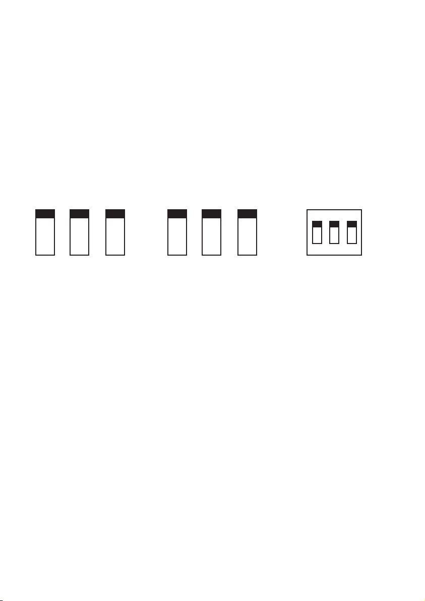
Inside the loco there are 6 switches in 2 banks of 3, controlling the lights
at each end of the loco independently. This means you can have
different setups for each end. There are also switches on the bottom of
the loco to control the tail lights at each end. See the diagrams below.
Note that all of the switches inside the loco have a central off position. If
this position is selected, some lighting functions will not work. Switches
should always be in either the top or bottom positions unless lighting is
not needed.
Switch 2 on the underside does not currently have a function.
For the use of these switches, please see the following section that is
applicable to your control system:
Analogue - Page 7
4 function digital chip - Page 8
6 function Digital chip - Page 9
ESU Loksound 5 chip - Page 10
K1 - K3 control the
lights at the cooler
group end of the
loco.
K4 - K6 control the
lights at the non-
cooler group end of
the loco.
Switch 1 - Tail at
non-cooler group end
Switch 3 - Tail at cooler
group end
K1 K2 K3 K4 K5 K6
ON
1 2 3

7
ON
1 2 3
Lighting - Analogue
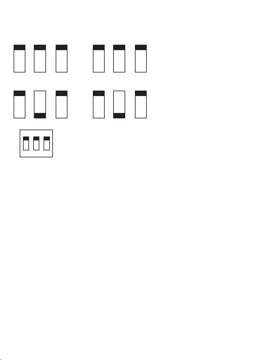
On analogue the following lights will show:
Marker lights
Day/Night lights
Tail lights
Cab lights cannot be controlled and will not light on analogue control.
All lights are directional when using analogue control.
By changing the position of K2 and K5, the headlights can be swapped
between day and night running.
To turn off the headlights/marker lights, set all switches to the central
position.
Tail lights are turned off and on using switches
1 and 3 under the loco.
K1 K2 K3 K4 K5 K6
Day Running
K1 K2 K3 K4 K5 K6
Night Running
Day headlight Night headlight

8
Lighting - 4 function digital control
4 function digital control functions:
Function 0/Light button - Headlights (Day/Night) & Marker lights
Function 1 - Tail lights front
Function 2 - Tail lights rear
Cab lights cannot be controlled and will not light on 4 function control.
By changing the position of K2 and K5, the headlights can be swapped
between day and night running.
ON
1 2 3
Tail lights are turned off and on using the
functions on the decoder.
Switches 1 and 3 should be in the ON position.
K1 K2 K3 K4 K5 K6
Day Running
K1 K2 K3 K4 K5 K6
Night Running
Day headlight Night headlight
9
Lighting - 6 function digital control
(DCR-21Pin-DirectV2)
6 function digital control functions:
Function 0/Light button - Marker lights
Function 1 - Tail lights front
Function 2 - Tail lights rear
Function 3 - Headlights front
Function 4 - Headlights rear
Cab lights cannot be controlled and will not light on 6 function control.
By changing the position of K2 and K5, the headlights can be swapped
between day and night running.
For optimum control, this model works best with a Hattons
DCR-21Pin-DirectV2 decoder. All factory fitted Digital models are
equipped with this decoder.
21 3
Tail lights are turned off and on using the
functions on the decoder.
Switches 1 and 3 should be in the ON position.
K1 K2 K3 K4 K5 K6
Day Running
K1 K2 K3 K4 K5 K6
Night Running
ON

10
Lighting - ESU Loksound 5 21MTC "MKL" (58449)
Day and night running lights
All lighting control is controlled via the decoder using the modes set up
with CV values and function selections to make operating the Class 66
with sound as realistic as possible. For full instructions on how to oper-
ate the lighting and sound functions, please see the Class 66 Sound
Instructions sheet supplied separately.
For optimum control, this model works best with an ESU 58449
Loksound 5 21MTC "MKL" decoder and Hattons Sure Sound. All factory
fitted Digital Sound models are equipped with this decoder.
All rolling stock on the national network has to have “group standard”
lighting to be allowed to run. This means there are 3 marker lights
forming a triangle (one just above each buffer and one centrally above
the cab windows) and 2 headlights. The Day headlight is on the
non-drivers side and points towards the side of the tracks, away from the
opposite running line so as not to dazzle oncoming drivers. The night
headlight is below the drivers windscreen and points along the running
rail to better illuminate reflective signs at night and also throw the light
further to aid track workers sighting of traffic.
21 3
K1 K2 K3 K4 K5 K6
For Loksound 5 use, switches should be set at these positions and
not used for any lighting changes
ON
Day running Night running Tail lights

11
Warranty Information
In the unlikely event of your locomotive developing a fault, please
inform us immediately. All of our models have a 12 month warranty
with us.
In the first 12 months
If the fault occurs within the first 12 months you may return the model
to us following these steps:
1. Email or call us and inform us of the exact fault and when it occurred
along with your invoice or order number.
2. Fill in the returns form at https://www.hattons.co.uk/returns.
2. With agreement from us, return the model (or faulty part of) to the
address below.
3. We will assess the model and take the appropriate action.
4. We will send out the new or repaired item as soon as possible.
We will always endeavor to replace models like-for-like but this may not
be possible once the model is sold out. In this case we will offer an
alternative or a full refund as in some cases a repair may not be
possible.
After 12 months
If a fault occurs after 12 months of the purchase date, then please
contact us. We may be able to help provide a spare part or repair but
please note that this service may carry a charge as the item will be out
of warranty.
We advise all customers to thoroughly check their models at the time of
purchase as faults occurring after 12 months cannot be treated as
warranty repairs, regardless of the amount of use the item has had.
For more information please visit https://www.hattons.co.uk/returns
Hattons Model Railways, 17 Montague Road
Widnes, Cheshire, WA8 8FZ
Table of contents
Other Hattons Originals Toy manuals

Popular Toy manuals by other brands


Global Hobby
Global Hobby Freestyle Instructions for final assembly

Hobbico
Hobbico FLWA4110 - PT17-XS instruction manual

Eduard
Eduard P-47D-25 interior S.A. Assembly instructions

LEGO
LEGO star wars 10188 instructions

Fisher-Price
Fisher-Price N6224 instructions

Hobartville Hobbies
Hobartville Hobbies Airco D.H.6 Assembly guide