Hattons Originals A3 User manual

Class A3 & A4
Operating Instructions
Hattons Model Railways
www.hattons.co.uk
0151 733 3655
Warranty Information
11
In the unlikely event of your locomotive developing a fault, please
inform us immediately. All of our models have a 12 month warranty
with us.
In the first 12 months
If the fault occurs within the first 12 months you may return the model
to us following these steps:
1. Email or call us and inform us of the exact fault and when it occurred
along with your invoice or order number.
2. With agreement from us, return the model (or faulty part of) to the
address below.
3. We will assess the model and take the appropriate action.
4. We will send out the new or repaired item as soon as possible.
We will always endeavor to replace models like-for-like but this may not
be possible once the model is sold out. In this case we will offer an
alternative or a full refund as in some cases a repair may not be
possible.
After 12 months
If a fault occurs after 12 months of the purchase date, then please
contact us. We may be able to help provide a spare part or repair but
please note that this service may carry a charge as the item will be out
of warranty.
We advise all customers to thoroughly check their models at the time of
purchase as faults occurring after 12 months cannot be treated as
warranty repairs, regardless of the amount of use the item has had.
Hattons Model Railways
17 Montague Road
Widnes
Cheshire
WA8 8FZ
Contents
1
2 Introduction
3 Box contents
4 Removing from wooden plinth
5 Fitting a digital decoder
6 Removing the bodyshell (A3)
7 Removing the bodyshell (A4)
8 Additional parts (A3)
9 Additional parts (A4)
10 Brake rigging
11 Warranty information
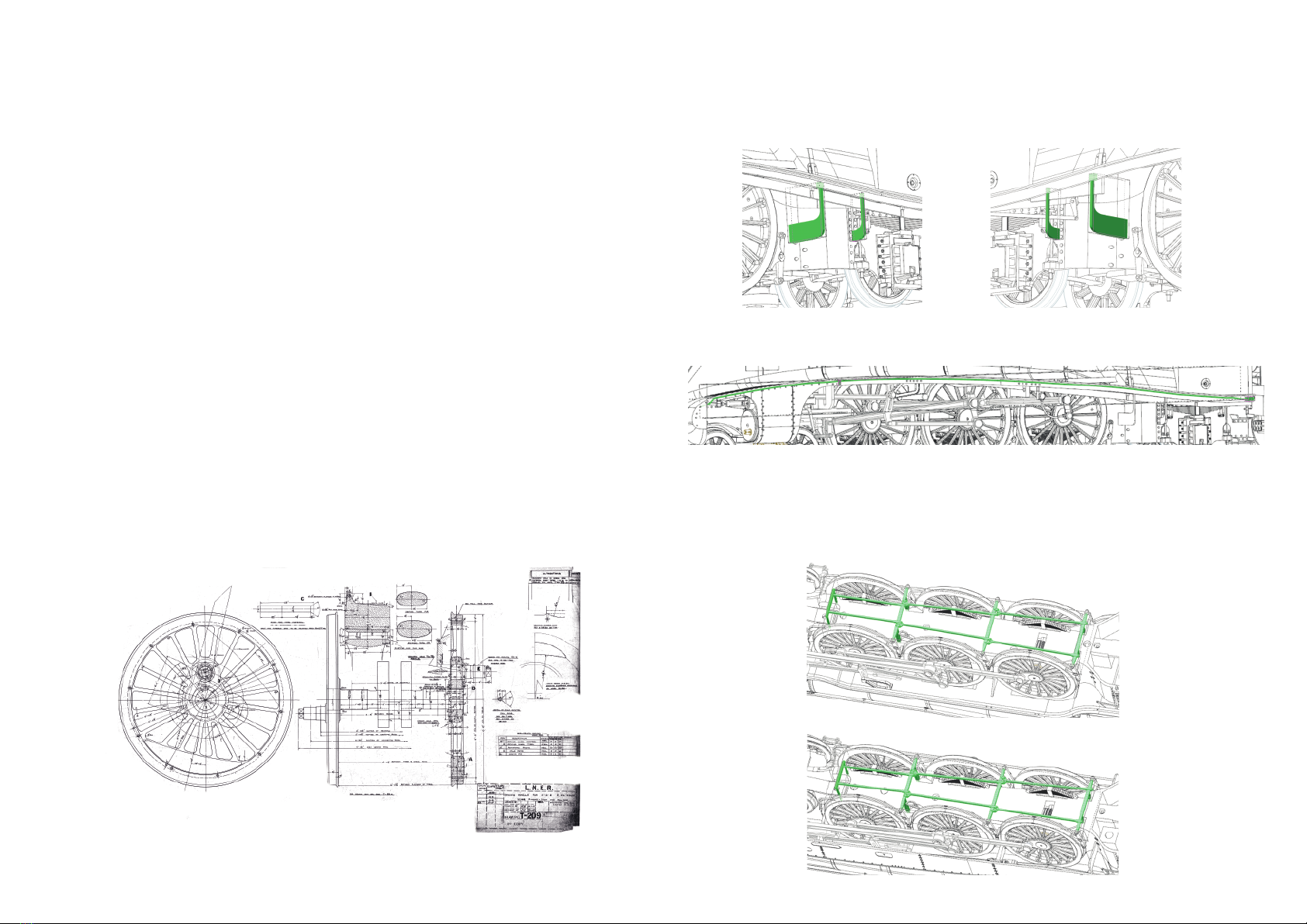
Additional parts (A4) - continued
Brake rigging
10
4. Running board supports - these are to be fitted with the Cutaway
valances
5. Valance pipe - for the cutaway valance, there is a pipe running along
the length of the left hand side. This is included for fitment if required.
The brake rigging is fitted between the brake block hangers as shown
below A3
A4

Introduction
Thank you for your purchase of the Class A3 or A4 in O
Gauge. With proper care and maintenance the loco will
provide many years of service.
The following manual will show you how to set up and
maintain your locomotive as well as where the small parts
that come with it should be situated and how to attach them.
If there is anything you cannot find in this manual or any
further questions that you may have, please do not hesitate
to contact us using the information at the bottom of this
page.
2
Additional parts (A4)
9
2. Coal load - can be used to represent a coal load in the tender
3. Valances - there are 2 versions, 1 original and 1 cutaway.
Both should be a push fit but may require a small amount of glue to
hold in place.
1. Fall plate - to be situated between the loco and tender.
Original
Cutaway

Box contents
• Locomotive & tender
• Wooden plinth
• 4 cross head screws with spacers
• Fall plate
• Coal load
• Brake rigging
• Valances (A4 only)
• Running board supports (A4 only)
• Valance side pipe (A4 only)
3
Removing the loco bodyshell (A4) - continued
Additional parts (A3)
7. Prise apart the body and chassis but do not remove them completely.
The bracket holding the expansion link (highlighted below) will need
to be removed from the body on both sides before it can be
separated completely.
(In case of damage, a spare expansion link bracket is included for each side)
1. Fall plate - to be situated between the loco and tender.
2. Coal load - can be used to represent a coal load in the tender
8
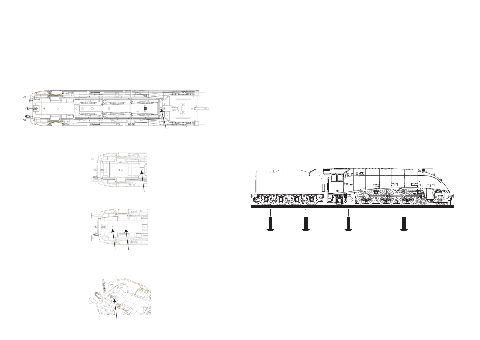
Removing from wooden plinth
Our locomotives come fixed to a wooden plinth by 4 screws.
This is to help protect them from damage in transit and aid in
removing them from the box.
To remove the loco and plinth as one unit, hold the
locomotive by the boiler and grip the box with your other
hand and gently pull up on the locomotive. Once the loco-
motive is clear of the box place it on a flat surface.
We recommend using the edge of a desk or table to remove
the screws. Slide the plinth off the table slowly by the tender
end first until the first screw is showing. Be sure that weight
is maintained on the front half to prevent it lifting.
Once the first screw is removed, slide the loco further back
and remove the second tender screw. Now the tender is
free, slide the loco back onto the table and rotate 180
degrees. Repeat the exercise for the loco section, removing
both screws. Once the last screw is removed you may lift the
loco off the plinth and place on your layout.
Same positions for
both A3 & A4
4
Removing the loco bodyshell (A4)
To remove the body on the A4:
1. Remove the screw holding the coupling bar to the tender.
2. Unplug the wire between the loco and tender from the socket on the
tender.
3. In front of the pony truck, remove the large screw.
4. Remove the screw holding in the spring plank and front bogie and
remove both as one part.
5. Remove the 2 screws in the centre of the flat section. Be careful, they
are very long!
6. Remove the pin from the rear of the coupling, remove the spring and
the washer and slide out the rest of the coupling.
7
4. Remove the tender body carefully, revealing the socket and plug.
5. Remove the blanking plate and replace with the decoder.
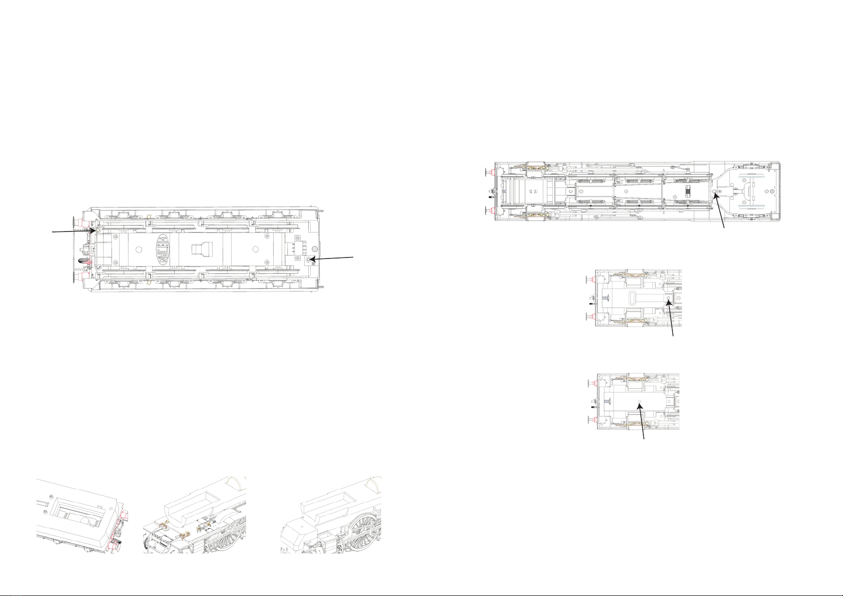
Fitting a digital decoder
Fitting digital sound
The Digital socket on this locomotive is designed to fit ESU L type
decoders (LokPilot L or LokSound L decoders). The socket is located in
the tender.
To access the socket:
1. Remove the screw holding the coupling bar to the tender.
2. Unplug the wire between the loco and tender from the socket on the
tender.
3. Remove the 2 screws shown below
Follow the above instructions first.
For the speaker, there are 2 potential positions:
1. Below the decoder socket (58mm x 23mm x 10mm).
2. Below the chimney in the boiler (58mm x 23mm x 10mm). To use this
socket you will need to run wires back to the tender. There are 2 spare
positions on the tender-to-loco connection which can be used for this if
required.
1 2 (A3) 2 (A4)
5
Removing the loco bodyshell (A3)
To remove the body on the A3:
1. Remove the screw holding the coupling bar to the tender.
2. Unplug the wire between the loco and tender from the socket on the
tender.
3. In front of the pony truck, remove the large screw.
4. Remove the screw holding in the spring plank and front bogie and
remove both as one part.
5. Remove the screw in the centre of the flat section. Be careful, it is very
long!
6. You may now remove the boiler and smokebox section in one part.
Lift the smokebox (front) first and then gently pull away from the cab
section. Be aware that the motor and weight inside the boiler will now
be free and may slide out from the boiler section as you perform this
action.
6
This manual suits for next models
1
Other Hattons Originals Toy manuals

Popular Toy manuals by other brands

Hasbro
Hasbro OMEGA SUPREME Transformers Energon instructions

Connoisseur Models
Connoisseur Models Six Wheeled All Third Coach instructions

PowerKites
PowerKites CROSSFIRE owner's manual

RTS
RTS 5M10 REIMS-GUEUX MARSHAL HUT Assembly instructions

Lionel
Lionel Railsounds Commander instruction manual

Lionel
Lionel LionChief Plus 2.0 AC-12 owner's manual

Accucraft
Accucraft FLYING SCOTSMAN operating instructions

Mattel
Mattel Barbie FGR64 instructions

KidKraft
KidKraft 65054 Assembly instructions

Radica Games
Radica Games Password Journal 75015 Specification sheet

Fisher-Price
Fisher-Price SUPERSIZE SANDBOX 75967 instructions

Hasbro
Hasbro Pup Pourri Barking Puppy 72475 instruction manual


