Haunted Pliers Destino Manual

Destino Build Instructions August 2020
1
Hey There,
It looks like you’ve got your hands on a Destino module! Thanks for supporting this first product from
Haunted Pliers, a tiny enterprise that hopes to make it easier for people to get into Eurorack and grow
their synths without spending big bucks or sacrificing aesthetics. Destino is the first in what is hoped to be
a series of cool little DIY modules with very competitive pricing.
Destino is designed to be a simple and useful headphone amplifier that is easy and fun to put together.
This makes it an ideal beginner project for people who are interested in building their own Eurorack
modules. Because of this, I’ve aimed these build notes at novices, so more advanced builders can feel free
to skip over things that they are already familiar with.
If you are a complete beginner to soldering then I recommend you check out some online tutorials before
starting this kit. In particular, Adafruit have loads of great resources for learning various electronics skills,
such as this soldering guide: https://learn.adafruit.com/adafruit-guide-excellent-soldering
message me on Instagram @hauntedpliers. I’d love to see where Destino ends up, so please send me
pictures of Destino in your rig to feature on the Haunted Pliers website and Instagram.
Happy Building!
Ad
Bill of Materials
Type
Quantity
Value
Resistor
4
2K
Resistor
2
47R
Diode
2
1N4001
Capacitor
2
100nF
Electrolytic Capacitor
2
22uF
Operational Amplifier
1
OPA2134PA
Power Header
1
---
Mono Socket
1
---
Stereo Socket
1
---
Alpha Potentiometer
1
100K
Knob
1
---
Knurled Nuts
2
---
Destino Build Instructions August 2020
2
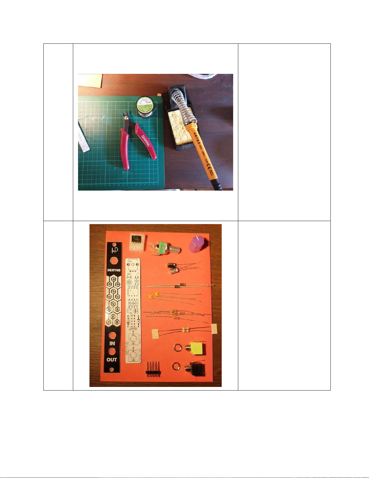
Tools
Tools!
You’re going to need a soldering
iron, some solder (lead free is
fine) and some side cutters.
You’ll also need a small flat head
screwdriver for the
potentiometer knob.
If you are interested, the
soldering iron in this picture is
an Antex CS18, which is
excellent value and great for
building most modules, but not
really suitable for precision
work.
I recommend using something
to protect your work-surface.
I’m using a cutting mat from an
arts & crafts store.
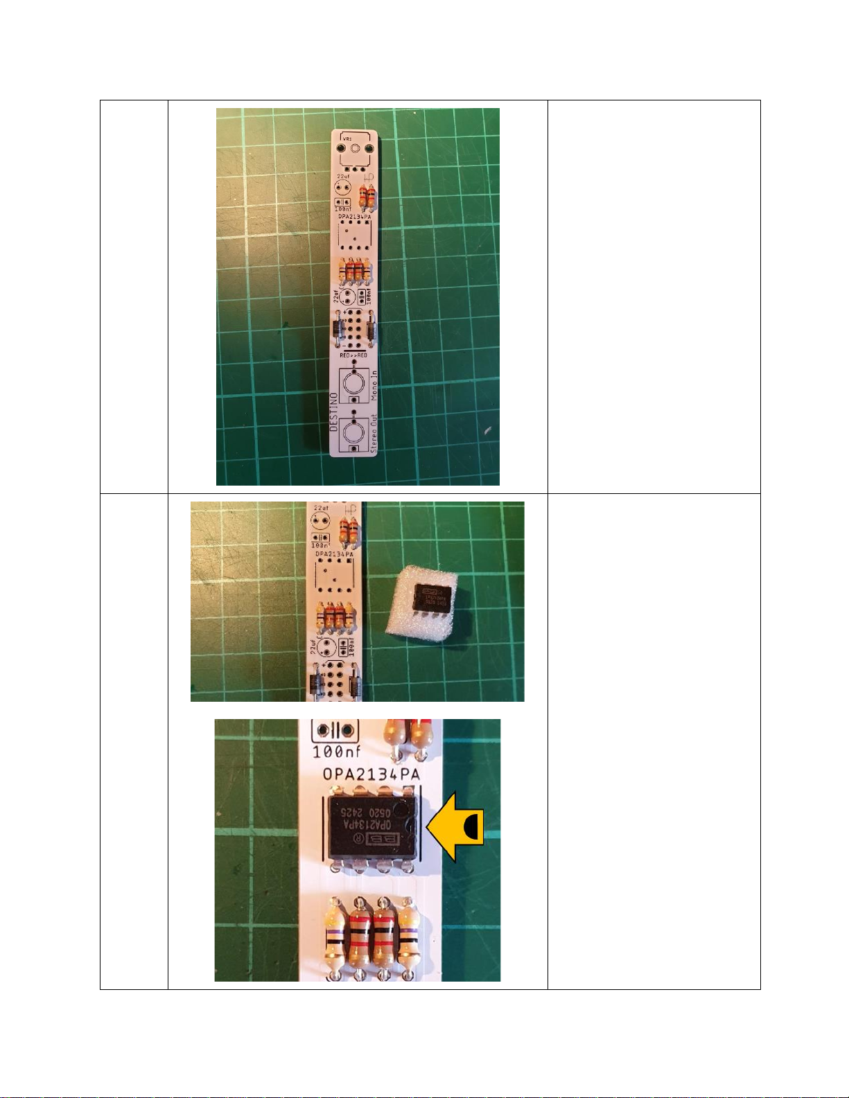
Parts
Parts!
Unpack the parts and look at
this all this stuff!
You may find it a bit weird that
the parts are in some sort of
envelope rather than a plastic
bag. This is just because I’m
trying to reduce the
environmental impact of these
kits. I choose the components
based on the ones with the least
plastic packaging when I order
in bulk from my suppliers.
If you want to check that you
have everything then you can
compare your parts with the bill
of materials on page 1.

Destino Build Instructions August 2020
3
Step 1
PCB
(Yeah, You Know Me)
Take out the Destino PCB and
flip it over to the side with the
electronics symbols printed on
it. This layer of print is called the
silkscreen and serves as a guide
to where the components will
go and in which orientation.
In this guide we’re going to add
the components in groups by
their type. We’ll start with the
components that sit lowest on
the board and work up to bigger
parts. This allows us to keep the
components nice and close to
the PCB while we’re soldering.
Step 2
2K
47R
Resistors
Destino uses two values of
resistor. 2K (which means
2000Ω) and 47R (which means
47Ω). You can tell the difference
by looking at the coloured
bands on the resistors.
2K:
Gold–Red–Black–Red
47R:
Gold–Black–Purple–Yellow
Sort the resistors into two
groups and bend the legs down
close to the body.

Destino Build Instructions August 2020
4
Step 3
Place the four 2K resistors into
the PCB in the locations shown
in the picture. Make sure you
get the 2K resistors in the gaps
labelled 2K.
Resistors are non-polarised
components, so it doesn’t
matter which way you put them
in the holes.
After you’ve placed the
resistors, turn the board over
and lay it on your work surface
to keep the resistors close to the
PCB when you are soldering
them. If you like, you can bend
the legs out a little to stop the
PCBs moving around during
soldering. You can do this with
all components that have long
legs.
Once soldered, snip the excess
wire off with your side cutters.

Destino Build Instructions August 2020
5
Step 4
Place the 47R resistors in the
remaining resistor holes and
solder as before.
Step 5
Diodes
Next are the diodes, which are
slightly larger than resistors.
Bend the legs of these using the
PCB as a guide to get the right
spacing, as shown in the picture.
The diodes are polarised
components. This means that
they have to be inserted the
correct way round or they won’t
work and your module won’t
handle power correctly.
The silver stripe on each diode
needs to line up with the black
stripe on the pictures on the
silkscreen. So, the one on the
left faces down and the one on
the right faces up.
Destino Build Instructions August 2020
6
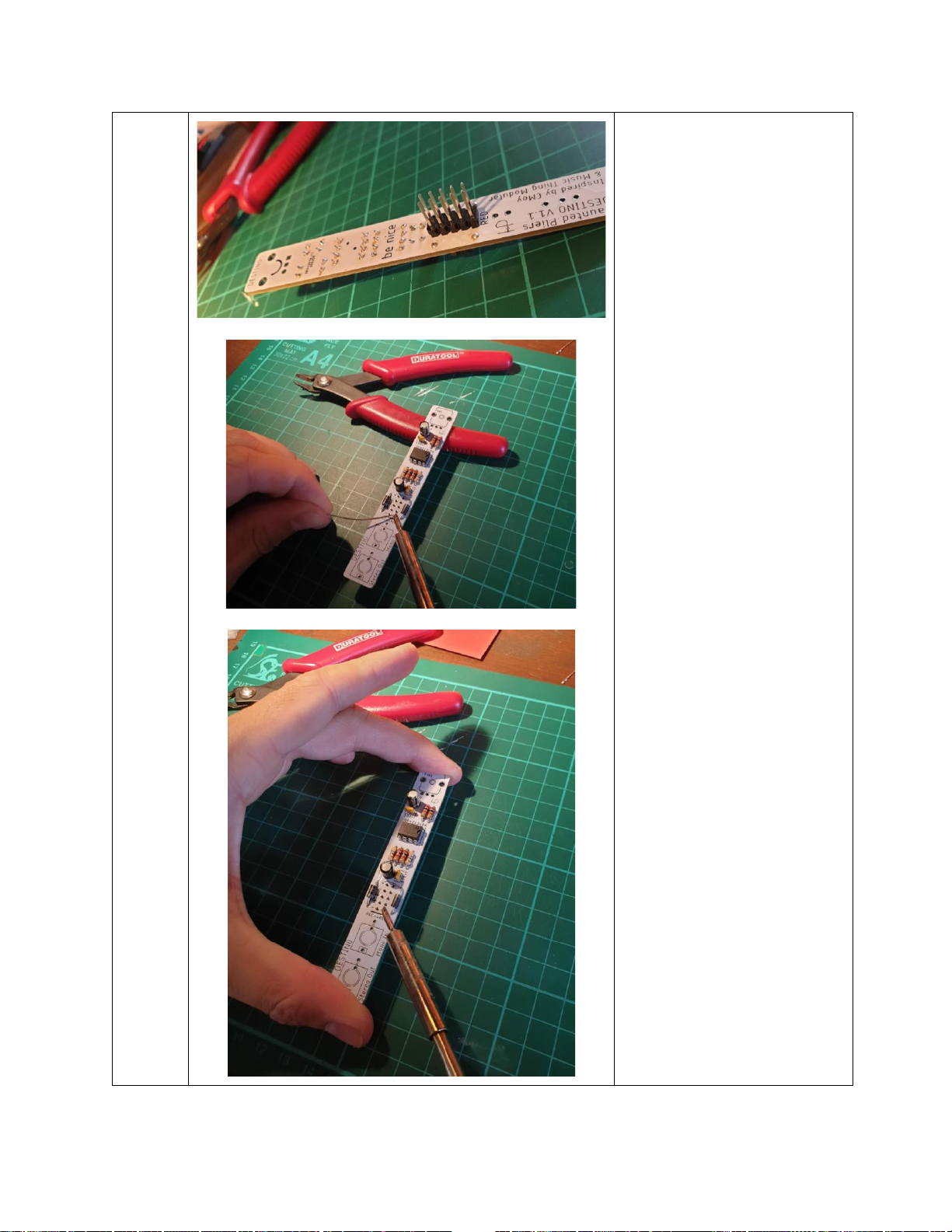
Step 6
OP-AMP (the chip)
The heart of Destino is the little
chip, which is also called an IC
(Integrated Circuit). This chip is
contains an audio amplifier
circuit.
Just like the diodes, the chip has
to be put into the circuit the
correct way around or the
module will not work. To do
this, the little semi-circle notch
has to face to the right of the
PCB. You may need to bend the
legs of the IC slightly inwards to
make it fit in the holes.
Soldering chips while keeping
them nice and flat against the
PCB can be tricky, as they don’t
have long legs to bend like
resistors or diodes. Because you
are already holding the
soldering iron and solder wire,

Destino Build Instructions August 2020
7
you have no hands free to keep
the chip aligned.
Though there are tools that hold
components in place when
soldering, one trick is to first flip
the board over so it is resting on
the component, then solder just
one of the legs, such as the top
right one.
After you’ve done that, use your
non-dominant hand to lightly
push down on the board while
briefly re-heating the solder on
that same one leg using your
soldering iron.
The solder on that leg will melt
and the chip should move into
position nice and flat against the
board.
When you remove the soldering
iron the solder will become solid
and the chip will be held in
place.
Check that the chip is now
sitting flat against the PCB. If it
is, you can go ahead and solder
the rest of the legs.
This soldering trick is pretty
handy for other components
with short legs, such as header
pins (Step 9) and phono jacks
(Step 10).

Destino Build Instructions August 2020
8
Step 7
Capacitors
There are two types of
capacitors in Destino. The first
ones we’ll put in are the 100nf
capacitors (nf = nano-farad),
which are smaller than the
other type. Because they are
non-polarized, they can go into
the PCB in either direction.
Again, you can bend the legs to
keep them in place when
soldering (as we did with the
resistors).

Destino Build Instructions August 2020
9
Step 8
Electrolytic Capacitors
The 22uf (uf = micro-farad)
electrolytic capacitors are
cylindrical, with one leg marked
with a silver strip and a minus
sign, as shown in the picture.
This is the negative leg of the
capacitor, while the other leg is
the positive leg. The positive leg
is also longer.
You have to put the positive leg
into the positive hole (marked
with a small + symbol) on the
PCB.
You can double check your
electrolytic capacitor placement
against this photo if you are
unsure. For both capacitors, the
silver strip should point towards
the closest set of resistors.
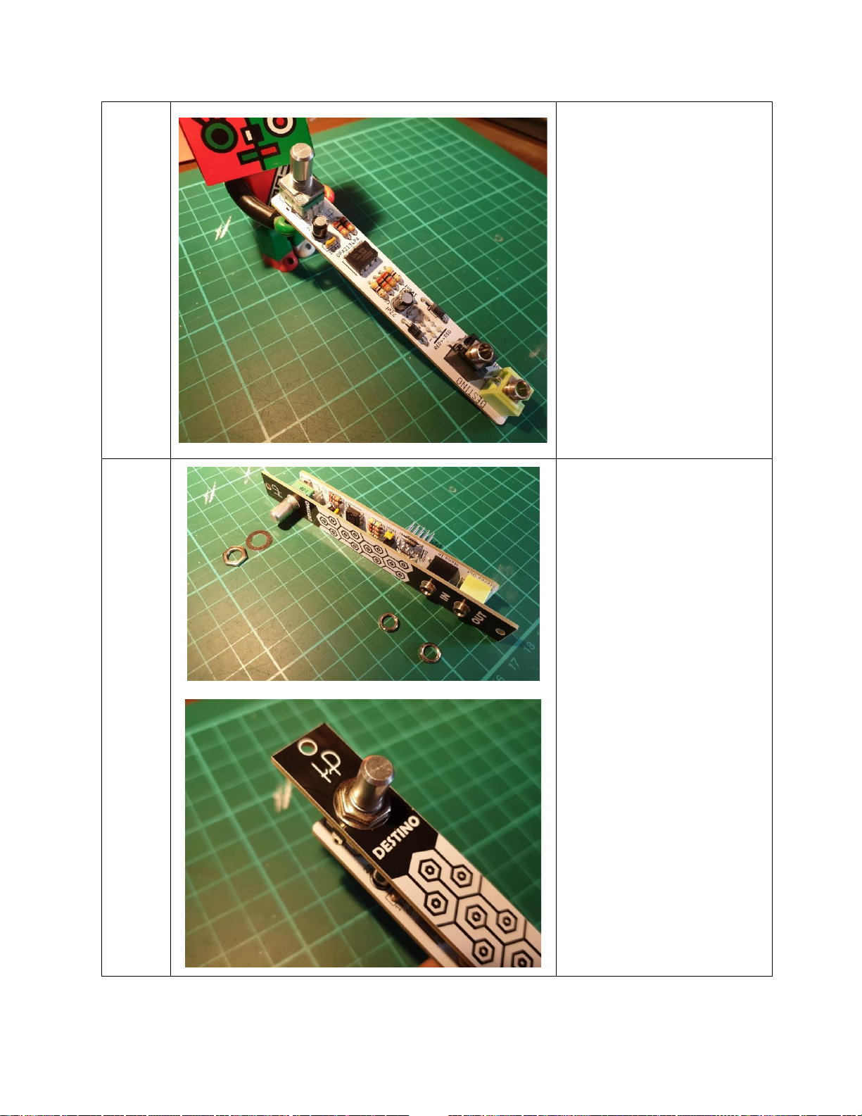
Step 9
Power Header
The power header is used to
connect Destino to the power
supply of your synth. It needs to
go on the opposite side of the
PCB to all the other
components.
As with the Op-Amp (Step 6), it’s
a good idea to just solder one
pin at first, to get everything
lined up nicely.
Destino Build Instructions August 2020
10
Because the header sticks out
quite a bit compared to the op-
amp, it can make the PCB quite
wobbly during soldering.
In this picture I’m resting the
top of the PCB on a handle of my
side cutters for stability while
soldering the bottom right pin.
As in Step 6, I’m then using my
non-dominant hand to lightly
push down on the board while
re-heating the solder to get the
header pins flat with the PCB.
Be careful not to hold the
soldering iron on the pin too
long while doing this or you may
melt the plastic part of the
header.
Once you’ve got it all nicely
aligned with the first pin
soldered, you can solder the
rest of the pins. Be careful with
those other nearby
components, it can get tight.

Destino Build Instructions August 2020
11
Step 10
Audio Jacks
There are two audio jacks. A
black mono one (because
Eurorack signals are mono) and
a green stereo one (because
headphones and speakers are
usually stereo). If you are colour
blind then the stereo jack is
slightly wider than the mono
jack.
If the little round bevelled nuts
are already screwed onto the
phono jacks then unscrew them
now and keep them handy.
Place the jacks onto the PCB,
with the green stereo one at the
bottom.
As before, flip the board over
and rest the top end on
something to keep it roughly
flat. Solder one leg of each jack,
get them lined up nicely before
soldering the other legs. When
lining up the jacks, try and keep
them inside the outlines on the
PCB. This will make the panel fit
on nicely.

Destino Build Instructions August 2020
12
Step 11
Potentiometer
The potentiometer is the
volume control for Destino.
First, remove the nut and
washer, but keep them handy.
When you place the
potentiometer in the PCB, you’ll
notice that it has three regular
legs and two bendy legs. These
bendy legs clip into the bigger
holes at the top of the PCB and
keep the potentiometer firmly
in place during use.
I used my side cutter handles to
keep the board stable while
soldering the three straight legs
of the potentiometer.
You don’t have to solder the
bendy legs of the
potentiometer, as the clip
design already holds them in
place nicely.
Destino Build Instructions August 2020
13
Step 12
Check your handiwork
Your Destino PCB is now fully
populated with electronic
components. Doesn’t it look
great?
Now, it’s time to check your
solder joints for any you may
have missed or look bad, as it
will be a bit more of a faff to fix
these after we put the panel on
in the next step.
Also check that all the
components match those in the
picture, in terms of placement
and orientation.
Step 13
The Panel
The holes in the panel simply fit
over the threaded parts of the
potentiometer and audio jacks.
Note that the potentiometer
and the audio jacks are different
heights, so the panel will not sit
parallel to the PCB. Don’t worry,
you won’t be able to tell when
it’s in your rack
Apply the washer and nut to the
potentiometer and the knurled
nuts to the audio jacks to hold
everything together. I find that
‘finger tight’is normally fine,
but you should probably use
tools for tightening if you are
going to be moving your rack
around a lot.

Destino Build Instructions August 2020
14
Step 14
The Knob
To install the knob, first turn the
potentiometer fully
anticlockwise. This position
corresponds to zero volume.
Then, use a flat head
screwdriver to loosen the little
screw on the knob.
Now, put the knob on the
potentiometer so that it points
between the D and E of
‘Destino’ and tighten the screw.
This will make the sweep of the
volume knob symmetrical.
DONE!
Finished
And that’s a wrap! Pat yourself
on the back, particularly if this is
your first DIY module.
I hope you enjoyed building
Destino and the instructions
were clear. If there were any
issues then please let me know
what they were and I’ll try and
fix them for future users.
Now, there’s just one thing left.

Destino Build Instructions August 2020
15
Finally…
Connect the Power
Now that we’re done it’s time to
connect the module to your
power supply and add it to your
Eurorack system.
Make sure you insert the
connector so that the red wire is
next to the ‘RED’ label on the
PCB.
Table of contents


