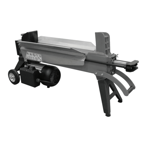
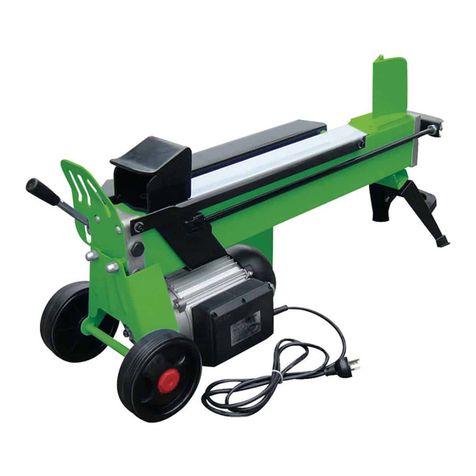
Haussmann LS15-20 User manual

ELECTRIC LOG SPLITTER
Operator’s manual (p.2)
FENDEUSE DE BÛCHES ÉLECTRIQUE
Guide de l’utilisateur (p.14)
MODEL / MODÈLE: LS15-20
59595076
CUSTOMER SERVICE / SERVICE À LA CLIENTÈLE: 1-866-206-0888
Our Customer service staff is available to help you. For help with product assembly, to report damaged or missing parts, or for any other
information, please call our toll-free number: 1-866-206-0888.
Register your product
We invite you to register your product online to make future communications easier. To do so, simply visit our website
www.haussmanntools.com.
SAVE THIS MANUAL
You will need this manual for safety instructions, operating procedures, and warranty. Put it and the original sales invoice in a safe, dry place
for future reference.
Notre personnel du service à la clientèle est disponible pour vous aider. Pour obtenir de l’aide pour le montage de votre produit, pour signaler
des pièces endommagées ou manquantes, ou pour toute autre information, veuillez composer notre numéro sans frais: 1-866-206-0888.
Enregistrez votre produit
www.outilshaussmann.com
CONSERVEZ CE GUIDE
Vous aurez besoin de ce guide pour les règles de sécurité, le fonctionnement et la garantie. Conservez-le avec votre facture d'origine dans
un endroit sûr au sec pour référence future.

ENGLISH
1. Handle
2. Wedge
3. Work table
4. Ram
5. Side supports
6. Hydraulic control lever
7. Wheel
8. Oil box
9. ON/OFF switch button
10. Bleed screw
11. Oil drain bolt with dipstick
12. Overload switch button
1. Poignée
2. Cale
3. Table de travail
4. Bélier
5. Supports latéraux
6. Levier de commande hydraulique
7. Roue
8. Boîte à huile
9. Bouton de commutateur MARCHE/
ARRÊT
10. Vis de purge
11. Boulon de vidange d’huile avec la
jauge
12. Bouton de commutateur de
surcharge
1
8
9
7
10
11
12
23456
1

ENGLISH
TABLE OF CONTENTS
• Safety symbols .................................................................................
• Safety instructions ............................................................................
• Additional safety warnings.................................................................
• Application.........................................................................................
• Technical data...................................................................................
• Assembly ..........................................................................................
• Operation ..........................................................................................
• Maintenance .....................................................................................
• Warranty ...........................................................................................
• Parts List ..........................................................................................
• Schematic Drawing ..........................................................................
SAFETY SYMBOLS
Please read all of the safety and operating instructions carefully before
using this tool. Please pay particular attention to all sections of this User
Guide that carry warning symbols and notices. Some of the following
symbols maybe used on this tool.
Do not expose to rain or use in damp locations
To reduce the risk of injury, user must read and
understand operator’s manual before using this
product
Always wear safety goggles or safety glasses with
side shields and a full face shield when operating
this product
Always wear nonslip, heavy-duty protective gloves
when operating this product
Always wear nonslip safety footwear when operating
this product
Always keep bystanders at least 10ft.(3m)away
Always keep hands away from the wedge and the
ram.
P.2
P.3
P.6
P.8
P.9
P.9
P.10
P.13
P.14
P.15
P.17
10’ 3m
2

ENGLISH
SAFETY INSTRUCTIONS
1. Work area safety
a) Keep work area clean and well lit. Cluttered or dark areas invite
accidents.
b) Do not operate power tools in explosive atmospheres, such as
in the presence of ammable liquids, gases or dust.Power tools
create sparks which may ignite the dust or fumes.
c) Keep children and bystanders away while operating a power
tool. Distractions can cause you to lose control.
2. Electrical safety
a) Always use a grounded three-wire extension cord and
receptacle that are made of rubber and intended for outdoor
use. The machine is designed to operate on 120 V AC
household current. The log splitter power cord has a grounding
prong. To avoid the possibility of shock it must always be used with
a properly grounded three-prong receptacle protected with a 20A
fuse. Never remove the ground prong from the plug.
b) Do not expose power tools to rain or wet conditions.
Water entering a power tool will increase the risk of electric shock.
c) Handle the cord carefully. Never use the cord for carrying,
pulling or unplugging the power tool. Keep cord away from heat,
oil, sharp edges and moving parts. Damaged or entangled cords
increase the risk of electric shock.
d) If operating a power tool in a damp location is unavoidable,
use a Ground Fault Circuit Interrupter (GFCI) protected supply.
Use of a GFCI device reduces the risk of electric shock.
e) When operating a power tool outside, use an outdoor
extension cord marked “WA” or “W”. These cords are rated for
outdoor use and reduce the risk of electric shock.
f) Do not use the equipment close to ammable objects.
3. Personal safety
a) Stay alert, watch what you are doing and use common sense
when operating a power tool. Do not use a power tool while you
are tired or under the inuence of drugs, alcohol or medication. A
moment of inattention while operating power tools may result in
serious personal injury.
b) Use personal protective equipment. Always wear eye
protection. Protective equipment such as dust mask, non-skid
safety shoes, hard hat, or hearing protection used for appropriate
conditions will reduce personal injuries.
c) Prevent unintentional starting. Ensure the switch is in the
off-position before connecting to power source, picking up
or carrying the tool. Carrying power tools with your nger on the
switch or plugging in power tools that have the switch on invites
accidents.
3

ENGLISH
d) Remove any adjusting key or wrench before turning the power
tool on. A wrench or a key left attached to a rotating part of the
power tool may result in personal injury.
e) Do not overreach. Keep proper footing and balance at all times.
This enables better control of the power tool in unexpected
situations.
f) Dress properly. Do not wear loose clothing or jewelry.
Keep your hair, clothing and gloves away from moving parts.
Loose clothes, jewelry or long hair can be caught in moving parts.
4. General Safety Rules
a) Know your power tool. Read the operator’s manual carefully.
Learn the applications and limitations as well as the specic
potential hazards related to this tool.
b) Guard against electrical shock by preventing body contact
with grounded surfaces. For example: pipes, radiators, ranges,
refrigerator enclosures.
c) Keep guards in place and in good working order.
d) Remove adjusting keys and wrenches. Form habit of checking
to see that keys and adjusting wrenches are removed from tool
before turning it on.
e) Keep work area clean. Cluttered areas and benches invite
accidents. DO NOT leave tools or pieces of wood on the tool while
it is in operation.
f) Do not use in dangerous environments. Do not use power tools
in damp or wet locations or expose to rain. Keep the work area well
lit.
g) Keep children and visitors away. All visitors should wear
safety glasses and be kept a safe distance from work area. Do not
let visitors contact tool or extension cord while operating.
h) Make workshop childproof with padlocks, master switches, or
by removing starter keys.
i) Don’t force the tool. It will do the job better and safer at the feed
rate for which it was designed.
j) Use the right tool. Do not force the tool or attachment to do a job
for which it was not designed.
k) Use the proper extension cord. Make sure your extension cord is
in good condition. Use only a cord heavy enough to carry the
current your product will draw. An undersized cord will cause a
drop in line voltage resulting in loss of power and overheating. A
wire gauge size (A.W.G.) of at least 14 is recommended for an
extension cord 25 feet or less in length. If in doubt, use the next
heavier gauge. The smaller the gauge number, the heavier the
cord.
l) Dress properly. Do not wear loose clothing, neckties, or jewelry
that can get caught and draw you into moving parts. Rubber gloves
and nonskid footwear are recommended when working outdoors.
Also wear protective hair covering to contain long hair.
m) Always wear safety glasses with side shields. Everyday
eyeglasses have only impact-resistant lenses, they are NOT safety
4

ENGLISH
glasses.
n) Secure work. Use clamps or a vise to hold work when practical,
it is safer than using your hand and frees both hands to operate the
tool.
o) Do not overreach. Keep proper footing and balance at all times.
p) Maintain tools with care. Keep tools sharp and clean for better
and safer performance. Follow instructions for lubricating and changing
accessories.
q) Disconnect tools. When not in use, before servicing, or when
changing attachments, blades, bits, cutters, etc., all tools should be
disconnected from power source.
r) Avoid accidental starting. Be sure switch is off when plugging in
any tool.
s) Never stand on tool. Serious injury could occur if the tool is
tipped.
t) Check damaged parts. Before further use of the tool, a guard or
other part that is damaged should be carefully checked to
determine that it will operate properly and perform its intended
function. Check for alignment of moving parts, binding of moving
parts, breakage of parts, mounting and any other conditions that
may affect its operation. A guard or other part that is damaged must
be properly repaired or replaced by an authorized service center to
avoid risk of personal injury.
u) Use the right direction of feed. Feed work into the blade against
the direction or rotation of the blade, only.
v) Never leave tool running unattended. Turn the power OFF and
unplug tool. Don't leave tool until it comes to a complete stop.
w) Protect your lungs. Wear a face or dust mask if the cutting
operation is dusty.
x) Protect your hearing. Wear hearing protection during extended
periods of operation.
y) Handle cord carefully.. Never carry tool by the cord or yank it to
disconnect from receptacle. Keep cord from heat, oil, and sharp
edges.
z) Use outdoor extension cords. When tool is used outdoors,
use only extension cords with approved ground connection that are
intended for use outdoors and so marked.
aa) Never use in an explosive atmosphere. Normal sparking of the
motor could ignite fumes.
bb) Inspect tools cords periodically. If damaged, have repaired
by a qualied service technician atan authorized service facility.
The conductor with insulation having an outer surface that is green
with or without yellow stripes is the equipment-grounding conductor.
If repair or replacement of the electric cord or plug is necessary, do
not connect the equipment-grounding conductor to a live terminal.
Repair or replace a damaged or worn cord immediately. Stay
constantly aware of cord location and keep it well away from the
rotating blade.
cc) Inspect extension cords periodically and replace if damaged.
dd) Keep tool dry, clean and free from oil and grease. Always
5

ENGLISH
use a clean cloth when cleaning. Never use brake uids, gasoline,
petroleum-based products, or any solvents to clean tool.
ee) Stay alert and exercise control. Watch what you are doing and
use common sense. Do not operate tool when you are tired. Do not
rush.
ff) Do not use tool if switch does not turn it on and off.
Have defective switches replaced by an authorized service center.
gg) Do not operate a tool while under the inuence of drugs,
alcohol or any medication.
hh) Always carry the tool only by the carrying handle.
ii) Use only recommended accessories listed in this manual or
addendums. Use of accessories that are not listed may cause the
risk of personal injury. Instructions for safe use of accessories are
included with the accessory.
jj) Tool service must be performed only by qualied repair
personnel. Service or maintenance performed by unqualied
personal could result in a risk of injury.
kk) When servicing use only identical replacement parts. Use of
any other parts may create a hazard or cause product damage.
ll) Always stay alert! Do not allow familiarity (gained from frequent
use of your tool) to cause a careless mistake. Always remember
that a careless fraction of a second is sufcient to inict severe
injury.
mm) Make sure the work area has ample lighting to see the work
and that no obstructions will interfere with safe operation BEFORE
performing any work using your tool.
nn) Always turn off the tool before disconnecting it to avoid
accidental starting when reconnecting to power supply. Never
leave the tool unattended while connected to a power source.
ADDITIONAL SAFETY WARNINGS
a) Do not allow anyone to operate the log splitter who has not
read the operator’s manual or has not been instructed on the safe
use of the splitter.
b) Never allow children or untrained adults to operate this
machine.
c) If someone is helping load logs to be split, Do not start the
machine until that person is clear of the area.
d) Never allow anyone to ride on the machine.
e) Never transport anything or anyone on the machine.
f) High uid pressures are developed in hydraulic log splitters.
Pressurized hydraulic uid escaping through a pin hole opening can
puncture skin and cause severe blood poisoning. Heed the following
instructions at all times:
i. Do not operate the machine with frayed, kinked, cracked, or
damaged hoses, ttings, or tubing.
ii. Stop the engine and relieve hydraulic system pressure before
6

ENGLISH
changing or adjusting ttings, hoses, tubing, or other system
components.
iii. Do not adjust the pressure settings of the pump or value.
iv. Never use your hand. Leaks can be located by passing
cardboard or wood over the suspected area. Look for
discoloration. If injured by escaping uid, see a doctor at once.
Serious infection or reaction can develop if proper medical treatment
is not administered immediately.
g) Keep the operator zone and adjacent area clear for safe,
secure footing.
h) Log splitter should be used only for splitting wood. DO NOT use
for other purposes unless the manufacturer provides attachments and
instructions.
i) Make sure the log splitter is on a level surface. Block the splitter
as required to prevent unintended movement.
j) Always operate the splitter from the manufacturer’s indicated
operator zone.
k) Logs to be split on ram-type units should be cut as squarely as
possible.
l) The machine owner should instruct anyone assisting him or her
in safe log splitting operation.
m) Always operate the log splitter with all safety equipment in
place and all controls properly adjusted for safe operation.
n) Always operate the log splitter at manufacturer’s
recommended speed.
o) When loading a ram-type log splitter, place your hands on the
sides of the log not at the ends. Never place your hands or any
part of your body between a log and any part of the log splitter.
p) On ram-type log splitters, never attempt to split more than one log
at a time unless the ram has been fully extended and a second log is
needed to complete the separation of the rst log.
q) On ram-type log splitters on which the logs are not square, the
longest portion of the log should be rotated down and the most
square end placed against the ram.
r) Clear debris from moving parts but only when the power source
is shut off.
s) Use only your hand to operate the log splitter controls. Always
unplug from the power source while repairing or adjusting the splitter
except as recommended by the manufacturer.
t) Circuit capacity and fuses:
i. Use only an electrical circuit having adequate capacity as
recommended by the log splitter manufacturer.
ii. “Blowing” a fuse or tripping a circuit breaker is usually a warning
that you are overloading the machine or have too many devices
taking power from the circuit, or both. Do not install a higher capacity
fuse!
u) Learn and understand all controls and the proper use of the
equipment.
v) Save these instructions. Refer to them frequently and use to
instruct other users. If you loan someone this tool, loan them these
instructions also.
7

ENGLISH
APPLICATION
Read all safety warnings and instructions. Failure to follow the
warnings and instructions may result in electric shock, re and/or
serious injury.
INTENDED USE
The HAUSSMANN electric log splitter is intended for splitting wood.
CHECK THE PACKAGE CONTENTS
Carefully remove the power tool from its packaging and check the
following parts are present:
-- Electric log splitter
-- Hydraulic control lever
If any parts are missing or damaged, please contact Customer Service
at 1-866-206-0888.
PRODUCT FEATURES
The numbering of the product parts refers to the illustration of the power
tool on page 1 (Fig. 1 & 2 ).
1. Handle
2. Wedge
3. Work table
4. Ram
5. Side supports
6. Hydraulic control lever
7. Wheel
8. Oil box
9. ON/OFF switch button
10. Bleed screw
11. Oil drain bolt with dipstick
12. Overload switch button
8

ENGLISH
TECHNICAL SPECIFICATIONS
Product code 59595076
Model number LS15-20
Voltage rating 120 V/60Hz
Current rating 15 AMP
Max. splitting force 5 TONS
Max. log diameter 10" (254 MM)
Max. log length 20" (508 MM)
ASSEMBLY
WARNING!Always ensure that the tool is switched off and the plug
is removed from the power source before making any adjustments or
performing maintenance procedures.
1. Unpacking
This product has been shipped completely assembled.
Carefully remove the machine and accessory from the box. Make sure
that all items listed on previous page are included. Inspect the machine
carefully to make sure no breakage or damage occurred during
shipping. Keep the packing material until you have carefully inspected
and satisfactorily operated the machine.
2. Assemble the hydraulic control lever (Fig. 3)
Turn the hydraulic control lever clockwise, to the steel bar to assemble
rmly.
(Fig. 3) (Fig. 4)
9

ENGLISH
OPERATION
WARNING!Always use the correcrt voltage: the voltage og the power
source must match the values on the nameplate of the tool.
1. Before using the machine (Fig 4, 5, 6 & 7)
Extension cords.
Use only 3-wire extension cords that have 3-prong grounding plugs
and 3-pole receptacles that accept the machine's plug. When using
the machine at a considerable distance from the power source, use an
extension cord heavy enough to carry the current that the machine will
draw. An undersized extension cord will cause a drop in line voltage,
resulting in a loss of power and causing the motor to overload. Use the
chart provided below to determine the minimum wire size required in
an extension cord. Only round jacketed cords listed by Underwriter's
Laboratories (UL) should be used.
When working with the tool outdoors, use an extension cord that is
designed for outside use. This is indicated by the letters "WA" on the
cord's jacket. Before using an extension cord, inspect it for loose or
exposed wires and cut or worn insulation.
2. Check the oil level before you start the log splitter (Fig 4 & 5 )
• Unplug the log splitter.
• Using the lift handle, stand the log splitter on the end with the
wheels (Fig 4).
• Using Allen wrench to remove the oil drain bolt and wipe the
dipstick clean (Fig. 5).
• Wipe the dipstick clean then reinsert it back into the oil tank.
• Remove the dipstick and check to see if the oil level is between the
rst and second groove on the dipstick (Fig.4).
• If there is not enough oil in the oil tank, add oil until the proper level
is reached.
• If there is the proper amount of oil in the oil tank, wipe the dipstick
clean then replace it in the oil tank and tighten the oil drain bolt
securely.
10

ENGLISH
(Fig. 5 & 6)
3. Check the bleed screw (Fig. 6 & 7).
• Place the machine on a level work surface and unplug the log
splitter.
• Loosen the bleed screw. Clockwise turn around the bleed screw to
the end, then, turn back the bleed screw counterclockwise by one
or two full turns(Fig. 6).
• Plug the log splitter and start the machine, place the left hand
on the hydraulic control lever and the right hand on the ON/OFF
switch button to start the machine (Fig. 7).
• Feel the air ow through the bleed screw, if no air ow detected,
slightly counterclockwise turn back the bleed screw until the air
ow can be felt.
• Check to make sure there are no leakages on the bleed screw.
Warning! Failure to loosen the bleed screw before operation will result
in permanent damage to the log splitter.
(Fig. 7) (Fig. 8)
4. Starting the log splitter (Fig. 7 & 8)
• Operator should be positioned at the rear of the log splitter (Fig. 8).
• Place the left hand on the hydraulic control lever and the right hand
on the ON/OFF switch button(Fig.7).
• Push down and hold the ON/OFF switch button, simultaneously,
push down and hold the hydraulic control lever to start the
machine.
• Both hands are required to start this product. The combination of
both steps starts the ram which pushes the log into the wedge.
• Release either hand could stop the ram in place, release both
hands could stop the machine completely and the ram will return to
the starting position.
13
12
11

ENGLISH
5. Splitting logs (Fig.9 & 10)
Always place logs lengthwise on the work table and resting rmly on the
side supports. Place logs at and in the direction of the grain.
Never angle the log to split it or place the log crosswise on the splitter.
Never split more than one log at a time.
Never split logs larger than 10” diameter or 20” long.
• Place log lengthwise and lying at on the work table. If the log is
small, place it against the wedge before starting the splitter.
• Using the right hand, push down and hold the ON/OFF switch
button, simultaneously, push down and hold the hydraulic control
lever with the left hand.
• The ram will push the log into the wedge and split the wood. The
overload switch will activate once overloaded, push the reset
button to restart the machine.
• Once the log is split, release both controls to return the ram to the
starting position.
• Repeat above steps to splitter more logs.
(Fig. 9) (Fig. 10)
6. Freeing a jammed log (Fig. 11)
Never try to knock the jammed log off the splitter.
Knocking the jammed log may damage the tool or y up the log to injure
someone nearby.
• Once a log jammed, release both hands to completely stop the
machine.
• After the ram is back at the starting position, insert a wood wedge
under the jammed log.
• Restart the log splitter to push the wood wedge completely under
the jammed log.
• If the log is still jammed, repeat the above steps until the log is
completely freed.
(Fig. 11)
12

ENGLISH
MAINTENANCE
WARNING! Always ensure that the tool is switched off and the plug
is removed from the power source before making any adjustments or
performing maintenance procedures.
Maintenance and Cleaning
• For safe and proper operation, always keep the tool and
ventilation slots clean.
• Regularly check to see if any dust or foreign material has
entered the slots near the motor and around the on/off
switch.
• Use a soft brush to remove any accumulated dust.
• Wear safety glasses to protect your eyes while cleaning.
• If the body of the tool needs cleaning, wipe it with a soft
damp cloth.
• A mild detergent can be used but no products containing
alcohol, petrol or other harsh cleaning agents.
• Never use caustic agents to clean plastic parts.
• Lubricate all moving parts at regular intervals.
Water must never come in contact with the tool.
Replacing hydraulic oil (Fig. 12)
The hydraulic oil in the log splitter needs to be changed every 150 hours
of use.
• Unplug the log splitter.
• Position the log splitter so that the motor end is slightly higher than
the oil drain plug.
• Using Allen wrench to remove the oil drain bolt.
• Drain the hydraulic oil from the oil tank into a four liter capacity
container.
• Once the oil has drained from the oil tank, turn the log splitter
vertical on the end with the wheels.
• Rell the oil tank with fresh hydraulic oil (3.7 quarts or 118 oz.).
Always use the recommended hydraulic oils, Shell Tellus 22,
Mobile DTE 11, Aral Vitam GF 22 and BP Energol HLP-HM 22.
• Place the cleaned dipstick into the oil tank. Remove and check the
oil level.
• NOTE: The oil level should be between the two grooves around
the bottom of the dipstick.
• Replace oil drain bolt. Tighten securely.
• Dispose old oil at an oil recycling centre.
13

ENGLISH
Oil level line
(Fig. 12)
Sharpening the wedge
After using the log splitter for some time, it may be necessary to sharpen
the wedge. Using a ne-toothed le, smooth any burrs or crushed areas
along the cutting edge.
WARRANTY
Thank you for investing in a HAUSSMANN power tool. These products
have been made to demanding, high-quality standards and are
guaranteed for domestic use against manufacturing faults for a period of
36 months from the date of purchase.
This guarantee does not affect your statutory rights. In case of any
malfunction of your tool (failure, missing part, etc.), please contact one
of our service technician at our toll free service line at 1-866-206-0888
from 8 AM to 6 PM, Monday to Friday, Eastern time. RONA reserves the
right to repair or replace the defective tool, at its discretion.
The product is guaranteed for 36 months if used for normal trade
purposes. Any guarantee is invalid if the product has been overloaded
or subject to neglect, improper use or an attempted repair other than by
an authorized agent. Heavy-duty, daily professional or hire usage are
not guaranteed. Due to continuous product improvement, we reserve
the right to change the product specication without prior notice.
Register your product
We invite you to register your product online to make future
communications easier. To do so, simply visit our website www.
haussmanntools.com.
14

ENGLISH
1
2
3
4
5
6
7
8
9
10
11
12
13
14
NO. DESCRIPTION
15
37
38
39
40
41
42
43
44
NO. DESCRIPTION
30
31
32
33
34
35
36
23
24
25
26
27
28
29
16
17
18
19
20
21
22
52
53
54
55
56
57
58
45
46
47
48
49
50
51
Screw bolt
Ring
Ring
Copper gasket
Piston
Ring
Piston ring
Screw bolt
Spring washer
Flat washer
Gasket
Fence
Screw bolt
Oil tank connector
Screw stick
Oil Cylinder
Spring
Front cover of oil tank
Ring
Screw
Ring
Piston rod assembly
Spring washer
Screw nut
benchmark
Screw bolt
Hand lever
Screw
Screw nut
PARTS LIST
Please refer to the schematic drawing on the next page.
Switch handle
Switch handle connector
Screw-H
Spring washer
Flat washer
Switch platen
Cylindrical pin
Apical plate components
Plate-V
Circlip
Spring
Oil inlet control assembly
Ring
Oil tube
ing
Screw nut
Ring
Hex bolts
Spring
Valve
Oil tank back cover
Ring
Copper washer
Screw nut
Spring
Ring
Copper washer
Screw bolt
Valve
15

ENGLISH
PARTS LIST
Please refer to the schematic drawing on the next page.
59
60
61
62
63
64
65
66
67
68
69
70
71
72
NO. DESCRIPTION
73
95
96
97
98
99
100
101
102
NO. DESCRIPTION
88
89
90
91
92
93
94
81
82
83
84
85
86
87
74
75
76
77
78
79
80
110
111
112
113
114
115
116
103
104
105
106
107
108
109
Stand
Base
Apical plate support assembly
Screw
Flat washer
Screw nut
Screw bolt
Spring washer
Flat washer
Wheel bracket
Wheel
Circlip
Wheel cover
Screw bolt
Screw bolt
Pump cover
Ring
Bearing sleeve
Pump
Circlip
Gearwheel
Steel ball
Gear shaft
Screw bolt
Motor support base
Screw nut
Motor front cover
Oil seal
Base-2
Stator
Motor housing
Rubber pad
Electrical box
Pressure line board
Screw
Screw
Washer
Spring washer
Screw
Over-load protection
Switch
Capacitance
Gasket
Electrical box cover
Screw nut
Screw bolt
Rubber ring
Screw nut
Power cord
Cylindrical key
Rotor
Circlip
Bearing
Circlip
Back cover of motor
Wind wheel
Wind wheel guard
Screw
16

FRANÇAIS ENGLISH
16
19
18
17
20
5
4
1
2
8
9
13
15
14
21
22
23
24
25
28
32
39
37 38
33
31
29
30
17
16
26
27
34
36
35
9
41
40
41
42
38
38
39
39
43
44
45
46 47
48
49
50
42
39
42
38
39
39
42
38
39
37
38
7
6
3
11
10
12
4
4
4
5
5
4
5
4
4
5
33
55
54
31
53
52
5
58
59
60
57
61
62
63
64
67
66
65
68
71
72
74
76
85
86
87
88
89
90
94
93
82
84
83
84
76
82
71
70
69
7875
75
78
79 80 81 82
77
92
93 91
82
84
84
83
82
66
67
66
67
73
100
101
102
109
110
103
104
105
106
107
111
114
116
115
112
113
98
99
95
96
97
56
51
108
SCHEMATIC DRAWING / SCHÉMA
17

FRANÇAIS
LISTE DES PIÈCES
Veuillez consulter la liste des pièces à la page précédente.
1
2
3
4
5
6
7
8
9
10
11
12
13
14
NO. DESCRIPTION
15
37
38
39
40
41
42
43
44
NO. DESCRIPTION
30
31
32
33
34
35
36
23
24
25
26
27
28
29
16
17
18
19
20
21
22
52
53
54
55
56
57
58
45
46
47
48
49
50
51
Poignée de commutateur
Connecteur de poignée de commutateur
Vis-H
Rondelle à ressort
Rondelle plate
Plateau de commutateur
Goupille cylindrique
Composants de la plaque apicale
Plaque-V
Circlip
Ressort
Ensemble de contrôle d’entrée d’huile
Anneau
Tube d’huile
Anneau
Écrou de vis
Anneau
Boulons à tête hexagonale
Ressort
Vanne
Couvercle arrière du réservoir d’huile
Anneau
Rondelle de cuivre
Écrou de vis
Ressort
Anneau
Rondelle de cuivre
Boulon de vis
Vanne
Boulon de vis
Anneau
Anneau
Joint de cuivre
Piston
Anneau
Anneau de piston
Boulon de vis
Rondelle à ressort
Rondelle plate
Joint
Guide
Boulon de vis
Connecteur du réservoir d’huile
Bâton de vis
Cylindre d’huile
Ressort
Couvercle avant du réservoir d’huile
Anneau
Vis
Anneau
Ensemble de la tige de piston
Rondelle à ressort
Écrou de vis
Référence
Boulon de vis
Levier à main
Vis
Écrou de vis
18

FRANÇAIS
59
60
61
62
63
64
65
66
67
68
69
70
71
72
NO. DESCRIPTION
73
95
96
97
98
99
100
101
102
NO. DESCRIPTION
88
89
90
91
92
93
94
81
82
83
84
85
86
87
74
75
76
77
78
79
80
110
111
112
113
114
115
116
103
104
105
106
107
108
109
Porte
Base
Ensemble de support de plaque apicale
Vis
Rondelle plate
Écrou de vis
Boulon de vis
Rondelle à ressort
Rondelle plate
Support de roue
Roue
Circlip
Housse de roue
Boulon de vis
Boulon de vis
Couvercle de pompe
Anneau
Douille de palier
Pompe
Circlip
Roue à pignon
Bille en acier
Axe de pignon
Boulon de vis
Base de support de moteur
Écrou de vis
Capot avant du moteur
Joint d’huile
Base-2
Stator
Logement du moteur
Patin en caoutchouc
Boîte électrique
Carte de ligne de pression
Vis
Vis
Rondelle
Rondelle à ressort
Vis
Protection contre les surcharges
Commutateur
Capacité
Joint
Couvercle de la boîte électrique
Écrou de vis
Boulon de vis
Anneau en caoutchouc
Écrou de vis
Cordon d’alimentation
Clé cylindrique
Rotor
Circlip
Palier
Circlip
Couvercle arrière du moteur
Roue
Protection de la roue
Vis
LISTE DES PIÈCES
Veuillez consulter la liste des pièces à la page précédente.
19
This manual suits for next models
1
Table of contents
Languages:
Other Haussmann Log Splitter manuals
Popular Log Splitter manuals by other brands

Powerhorse
Powerhorse M1156I owner's manual

Craftsman
Craftsman 247.34625 owner's manual

Camon
Camon Turbo 7 operating instructions

Elem Garden Technic
Elem Garden Technic FB1500-5TEG52SC Original instructions

Villager
Villager LS 7 T Original Operator's Manual

Gude
Gude GHS 370/4TE Translation of the original instructions

Posch
Posch 6T COMPACT PLUS operating instructions

Bell
Bell VS K9 N Manual for use and maintenance

Gude
Gude DHH 1250/12 T Translation of original operating instructions

MTD
MTD 500 Series Operator's manual

kinetic
kinetic T20 Instruction & assembly manual

Dirty Hand Tools
Dirty Hand Tools 100171 Operation manual