Havahart 5144G User manual

Model 5144G
Quick Setup Guide
Ensure that the following components are included with your system. If a component
is missing, please call 1-800-800-1819, Option 1.
Controller
USB Cable
USB AC Adapter
Master Base
3 Bases
4 AC Adapter Power Cords For Bases
Removable Wall-Mount Adhesive Strips
4 Screws and 4 Wall Anchors
Collar
2 RCR123 Batteries For Collar
Battery Charger
Extra Set Of Collar Probes For Short-Haired Dogs
Heart-Shaped Collar Tester
74 White Training Flags, 1 Blue Training Flag
Instructional DVD
Instruction Manual
Troubleshooting Guide
A
A
I
J
B
B
J
K
C
D
K
L
D
EE E
L
M
E
F
F
F
F
F
G
C
G
H
H
I
M
N
N
Congratulations for completing the setup of your Havahart® Wireless
Custom-Shape Wireless Dog Fence.
You are now ready to start training and enjoying your fence.
!
IMPORTANT MESSAGE
Proper training of your dog is the most critical element to ensure the successful
operation of your wireless dog fence. Consult the training section of the
instruction manual once you have set up your wireless dog fence.
Need Assistance? WE CAN HELP!
CALL 1-800-800-1819, OPTION 1.
There is no need to return this product to the store for
any reason. Contact Havahart® Wireless Directly!
Havahart® Wireless
Woodstream Corporation
69 North Locust Street
Lititz, PA 17543 | 1-800-800-1819
www.HavahartWireless.com
PRIOR TO INSTALLATION
Fully Charge the System Controller and Batteries for 3 hours.
AVERAGE SYSTEM SETUP TIME IS 2 HOURS.

Setting Up the Bases
1
Welcome
Setting Up the Bases
1Havahart® Custom-Shape Wireless Dog Fence
www.HavahartWireless.com 2
Havahart® Custom-Shape Wireless Dog Fence
1-800-800-1819, Option 1
It is important that you understand the image below before getting started.
ROAMING AREA - Area inside the
Trigger Zone where your dog is free
to play. Capable of expanding up to
500 feet in any direction.
TRIGGER ZONE - Zone located
outside the Roaming Area that forms
the Fence Boundary. May be up to 13
feet wide.
EXCLUSION ZONE - Target areas
on your property where you wish
to restrict your dog’s access, such as
a flower bed, pool or patio. Up to 4
Exclusion Zones can be created.
Congratulations and thank you for choosing the Custom-Shape Wireless Dog
Fence from Havahart® Wireless the leading innovator of digital wireless
fence solutions.
The Quick Setup Guide can help you get your wireless fence up and running quickly
and efficiently. It is not a replacement for the instruction manual. IT IS IMPORTANT
that you read and follow all safety guidelines and directions detailed in the
Instruction Manual to ensure the safe and effective operation of your system.
Installing the Bases:
• The best choice to place your Bases is on
windows or outer walls in the furthest corners
of your home, near 120V AC power outlets,
spaced as far apart as possible, but a minimum
of 20 feet apart.
• If Bases must be in the same area, such as a
garage, it is better to place Bases on adjacent
walls than on the same wall.
• DO NOT place the Bases within 3 feet of metal
objects, such as mirrors, microwaves, home
appliances, an electric power meter, air conditioning units, metal
grates/fences, metal screened porches, downspouts, large bushes or other objects
immediately outside the wall. Move the Bases so that they have the best communication
path to the outside.
• Position the Master Base A (see USB port on bottom) in an interior corner wall near the
area where your dog spends most of his time outdoors. Using the removable wall-mount
adhesive strips (see Figures below), place it approximately 6 feet off the floor. Do NOT
plug it in at this time.
• Attach the other 3 Bases to walls in the remaining 3 corners of your home. Do NOT plug
them in at this time.
Figure 1.1a Figure 1.1b Figure 1.2
Illustration A
Exclusion Zone
NOTE:
Charge the Controller and both RCR123 Batteries for 3 hours prior to use (see
Recharging a Battery in the Instruction Manual). Connect the Controller, via the USB
Cable, to your computer while it is turned on or to the USB AC Adapter and wall outlet.
If a Found New Hardware screen appears when you connect the Controller to your
computer, press Cancel.
!
IMPORTANT MESSAGE
Proper training of your dog is the most critical element to ensure the successful
operation of your wireless dog fence. Consult the training section of the manual
once you have set up your wireless dog fence.
Need Assistance? WE CAN HELP!
CALL 1-800-800-1819, OPTION 1.
There is no need to return this product to the store for any reason.
Contact Havahart® Wireless Directly!
Woodstream Corporation
69 North Locust Street
Lititz, PA 17543
Deck
Flower
Garden
Pool
Shed
Swing Set
S
h
ed
Exclusion
Zone 2
Exclusion
Zone 1
Exclusion
Zone 2
Master Base A
Base D
Base C
Base B

Setting Up the Bases
1
Setting Up the Bases
Setting Up the Bases
Havahart® Custom-Shape Wireless Dog Fence
www.HavahartWireless.com
Havahart® Custom-Shape Wireless Dog Fence
1-800-800-1819, Option 1
Accessing the Wireless Fence Tracker: Activating The Bases (continued):
• Touch the screen of the Controller to turn it on and
press “Get Started” (see Screen 1.0).
• Press “System” (see Screen 1.1).
• Press “Complete” (see Screen 1.2) to add the
Master Base A to the System. The indicator light will
turn solid green.
• Walk clockwise to the next Base to the right of the
Master Base A and plug it into a power outlet. After
the indicator light turns green, press “Complete” on
the Controller to add the Base to the System.
• Walk clockwise to the remaining 2 Bases and repeat
these steps to activate them. (see Illustration C).
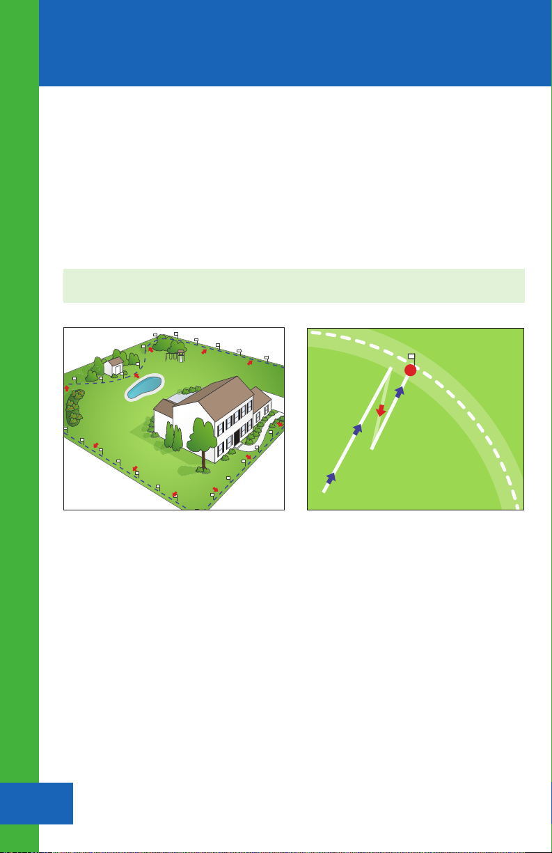
• Your Bases should now be properly oriented on
the Wireless Fence Tracker. The Master Base A will
always appear at the intersection or crosshairs
of the 2 bold lines. Base B will always appear
directly to the right of the Master Base A on
the horizontal bold line. Bases C and D will then
appear in their respective relative positions (see
Figure 2.3a).
• Press “Yes” to setup your Fence Boundary/
Trigger Zone.
Figure 2.0 Screen 1.0
Screen 1.1
Screen 1.2
Figure 2.3a
Activate the Bases in a clockwise fashion.
Deck
Flower
Garden
Pool
Shed
Swing Set
S
h
ed
Exclusion
Zone 2
Exclusion
Zone 1
Exclusion
Zone 2
Master Base A
Base D
Base C
Base B
Illustration C
1
2
3
4
3 4
The Wireless Fence Tracker program will allow you to
see approximately where your wireless Fence Boundary
lies and where your dog is and has been in relation to
your Base locations. Your home computer will need
internet access in order to operate the program.
• Make sure the computer is located within 6 feet of the
Master Base A.
• To access the Wireless Fence Tracker, visit
www.HavahartWireless.com/myaccount.
• If you don’t have an account, create one to gain
secure access to the program.
• The Wireless Fence Tracker Grid should appear with
4 Bases on the screen (see Figure 2.0). At this time,
these Bases do not yet represent your Bases.
• Disconnect the fully charged Controller from the
USB cable.
• Connect your computer to the Master Base A via
the USB cable.
Activating The Bases:
• Add the Bases, one at a time into the System, starting
with the Master Base A. Plug the Master Base A into
the power outlet.
• The indicator light will flash green to show that the
Base is powered on. Do not plug in the other
Bases yet.
• On the Wireless Fence Tracker, select “Start” to begin
recording. As you activate your Bases, they will move
to their actual locations on the screen.

Setting Up the Bases
1
Setting Up the Bases
Setting Up the Bases
Havahart® Custom-Shape Wireless Dog Fence
www.HavahartWireless.com
Havahart® Custom-Shape Wireless Dog Fence
1-800-800-1819, Option 1
Accessing the Wireless Fence Tracker: Activating The Bases (continued):
• Touch the screen of the Controller to turn it on and
press “Get Started” (see Screen 1.0).
• Press “System” (see Screen 1.1).
• Press “Complete” (see Screen 1.2) to add the
Master Base A to the System. The indicator light will
turn solid green.
• Walk clockwise to the next Base to the right of the
Master Base A and plug it into a power outlet. After
the indicator light turns green, press “Complete” on
the Controller to add the Base to the System.
• Walk clockwise to the remaining 2 Bases and repeat
these steps to activate them. (see Illustration C).
• Your Bases should now be properly oriented on
the Wireless Fence Tracker. The Master Base A will
always appear at the intersection or crosshairs
of the 2 bold lines. Base B will always appear
directly to the right of the Master Base A on
the horizontal bold line. Bases C and D will then
appear in their respective relative positions (see
Figure 2.3a).
• Press “Yes” to setup your Fence Boundary/
Trigger Zone.
Figure 2.0 Screen 1.0
Screen 1.1
Screen 1.2
Figure 2.3a
Activate the Bases in a clockwise fashion.
Deck
Flower
Garden
Pool
Shed
Swing Set
S
h
ed
Exclusion
Zone 2
Exclusion
Zone 1
Exclusion
Zone 2
Master Base A
Base D
Base C
Base B
Illustration C
1
2
3
4
3 4
The Wireless Fence Tracker program will allow you to
see approximately where your wireless Fence Boundary
lies and where your dog is and has been in relation to
your Base locations. Your home computer will need
internet access in order to operate the program.
• Make sure the computer is located within 6 feet of the
Master Base A.
• To access the Wireless Fence Tracker, visit
www.HavahartWireless.com/myaccount.
• If you don’t have an account, create one to gain
secure access to the program.
• The Wireless Fence Tracker Grid should appear with
4 Bases on the screen (see Figure 2.0). At this time,
these Bases do not yet represent your Bases.
• Disconnect the fully charged Controller from the
USB cable.
• Connect your computer to the Master Base A via
the USB cable.
Activating The Bases:
• Add the Bases, one at a time into the System, starting
with the Master Base A. Plug the Master Base A into
the power outlet.
• The indicator light will flash green to show that the
Base is powered on. Do not plug in the other
Bases yet.
• On the Wireless Fence Tracker, select “Start” to begin
recording. As you activate your Bases, they will move
to their actual locations on the screen.

Placing Fence Boundary Training Flags :
(see Illustration E on Page 6)
• Use the blue flag to mark your starting point. Place
boundary flags in the ground, 6 feet apart from one
another to establish the desired perimeter of your
boundary.
• Once you have confirmed that all flags are in the proper
position, press “Complete” (see Screen 3.5).
Recording the Fence Boundary/Trigger Zone:
Setting Up the Fence Boundary/Trigger Zone
2
Setting Up the Fence Boundary/Trigger Zone
Setting Up the Fence Boundary/Trigger Zone
5Havahart® Custom-Shape Wireless Dog Fence
www.HavahartWireless.com 6
Illustration C
Screen 3.7
Screen 3.5
START END
Screen 3.6
Screen 3.7
Screen 3.8
Recording the Fence Boundary (continued):
• When recording your Fence Boundary, keep the
Controller over the flags at all times and
between your body and the Bases as your
body may affect the signal and cause the
boundary to shift (see Factors Affecting Signal
Strength in the Instruction Manual).
• Starting at the blue flag, hold the Controller at
waist level over the flag, wait 5 seconds and
press “Record” (see Screen 3.6.)
• Walk the flag line (see Illustration E) at a SLOW
deliberate pace until you reach the blue flag and
press “Done” (see Screen 3.7). Slow down coming
around corners. Stop for 1 second at each corner
if you want the system to make a sharp corner
point.
• A congratulatory screen will appear. Press “NEXT”.
• The Wireless Fence Tracker will show the Fence
Boundary in green. The blue circles track the
Controller and should closely, but not perfectly
overlay the green line (see Figure 3.0).
Havahart® Custom-Shape Wireless Dog Fence
1-800-800-1819, Option 1
Screen 3.8
Illustration D
SHED
Pause
Wait 5 seconds,
then Continue
Figure 3.0
PAUSE FEATURE NOTE:
During fence recording, you can press “Pause”
(see Screen 3.7) to stop, go around an object (such as
a shed or other large object), and record the Fence
Boundary through the object (see Illustration D).
After you walk around the object, wait 5 seconds
and then press “Continue” to continue recording
your Fence (see Screen 3.8).
Illustration E

Setting Up the Exclusion Zone(s)
Setting Up the Collar(s)
7Havahart® Custom-Shape Wireless Dog Fence
www.HavahartWireless.com 8Havahart® Custom-Shape Wireless Dog Fence
1-800-800-1819, Option 1
Setting Up the Exclusion Zone(s) Optional
3
Placing Exclusion Zone Training Flags:
• Place flags in the ground, six feet apart from one
another to establish the desired Exclusion Zone
boundary.
• Using the Controller, select “ExZones” from the main menu.
• Select “Add ExZone” (See Screen 4.3).
• Select the ExZone you would like to add ie. EXZONE1
(see Screen 4.4).
• Once you have confirmed that all flags are in the proper
position, press “Complete”.
Recording an Exclusion Zone:
• The Pause feature can be used in the same way you
recorded your Fence Boundary (see Page 5).
• Because Exclusion Zones are smaller than your fence you
must walk about 4 feet or one pace inside the flag line.
Make sure to keep the Controller between your body
and the Bases as your body may affect the signal and
cause the boundary to shift (see Factors Affecting Signal
Strength in the Instruction Manual).
• Starting about 4 feet or one pace inside the first flag, hold
the Controller at waist level, wait 5 seconds and press
“Record” (see Screen 4.6). Walk at a QUICK deliberate
pace all the way around the inside of your Exclusion Zone
ending where you started. Slow down coming around
corners. Stop for 1 second at each corner if you want the
system to make a sharp corner point.
• When you return to your starting point, press “Done” and
a Congratulatory screen will appear.
• Press “Yes” if you would like to name your Exclusion
Zone (see Screen 5.2).
• The Wireless Fence Tracker will show the Exclusion Zone
also in green. The blue circles track your Controller and
should closely, but not perfectly overlay the green line (see
Figure 4.0).
Screen 4.3
Screen 4.4
Screen 4.6
Screen 5.2
Figure 4.0
Setting Up the Collar(s)
4
Installing a Battery:
• Make sure the Battery is fully charged.
• Turn the Battery Cap counterclockwise, remove it,
and insert the Battery (see Figure 5.0).
• Replace the Battery Cap and turn it 1/4 turn
clockwise to lock it in place. The Collar Light will flash green. If it does not, shake the
Collar gently as the Collar is in sleep mode (see the Havahart® Wireless Collar Light Chart).
Activating a Collar:
• The system allows you to activate up to 2 Collars
using the Controller.
• Position the Collar near the Master Base.
• Select “Collars” from the main menu.
• Select “Add Collar” (see Screen 6.3).
• Press “Next” (see Screen 6.4).
Havahart® Wireless Collar Light Chart:
-Asleep OR
-Battery is too Low OR
-Battery is not in the Collar
-Not added to System OR
-System is off OR
-Only Fence is on
-Paired to System and
operating normally
-Low Battery
OR
-Boundary Breach
Collar Light ActionStatus
Off
Fast Green Flash
every second
Slow Green Flash
every 4-5 seconds
Red Flash
Shake gently and watch for the Light to
flash green. Make sure a fully charged
Battery is in the Collar.
Make sure the Fence is on and add the
Collar to the System.
No action required.
Charge the Battery OR
Return the dog to Roaming Area.
Figure 5.0
+
-
Collar Light
Screen 6.4
Screen 6.3
8
RCR123 3V

Setting Up the Collar(s)
Setting Up the Collar(s)
9Havahart® Custom-Shape Wireless Dog Fence
www.HavahartWireless.com 10
Havahart® Custom-Shape Wireless Dog Fence
1-800-800-1819, Option 1
Activating a Collar (continued):
• While gently shaking a Collar to keep it awake, press the
Collar that you would like to activate (see Screen 6.5).
• A Congratulatory screen will appear (see Screen 6.7). Press
“Yes” if you would like to name the Collar (see Screen 7.5).
Adjusting the Correction Level of a Collar:
• Select “Collars” from the main menu.
• Press “Edit Collar Correction Level” (see Screen 7.3).
• Press Collar that you wish to adjust (see Screen 7.4).
• Press “LEVEL UP” or “LEVEL DOWN” to adjust the
correction level to the desired setting -- 5 being the
highest correction level and 1 being the lowest
correction level (see Screen 7.9).
• Press “APPLY” and a confirmation screen will
display briefly.
Screen 6.5
Screen 6.7
Screen 7.5
Screen 7.4
Screen 7.3
Screen 7.9
Setting Up the Collar(s)
4
Testing the Trigger Zone:
• To confirm that the location of the actual boundary
is correct, Test Your Trigger Zone in 2 Ways - It is
necessary to perform both steps for complete
verification.
• In both cases, make sure the Collar is set to Tone Only.
Extend your arm down by your side and hold the Collar
by the Grey Battery Housing so that you can see the
Collar Light (see Figure 6.0). Make sure to keep the
Collar between your body and the Bases as your
body may affect the signal and cause the boundary
to shift (see Factors Affecting Signal Strength in the
Instruction Manual).
Step 1:
• Walk a parallel path to your boundary, 10 feet inside
the flag line, at the same SLOW deliberate pace and
in the same manner in which you recorded the Trigger
Zone while gently moving the Collar to keep it awake.
• The Collar alarm should not tone as you walk along the
inside of your boundary. If the Collar alarm tones during
your Trigger Zone test, make a note of the location and
continue walking inside your Fence Boundary.
• Once complete, look at the Wireless Fence Tracker. The
path that you walked should be represented by little red
circles (see Figure 7.0).
• The red circles should closely, but not perfectly run
parallel to the green line .
• If you notice any extreme dips, loops or crossovers in
your fence, you may you may want to Remove your
Fence and re-record. In most cases, you may need to
simply move flags one way or the other to be closer
to the boundary. If the Fence Boundary is still not within
your level of tolerance and if re-recording does not solve
the problem (consult your Troubleshooting Guide), it
may be necessary to reposition one or more of your
Bases so that there are less signal limiting obstructions
(see Page 8 in the Instruction Manual) between the Fence
Boundary and your Bases (see Factors Affecting Signal
Strength in the Instruction Manual).
Figure 6.0
Figure 7.0

Setting Up the Collar(s)
Setting Up the Collar(s)
9Havahart® Custom-Shape Wireless Dog Fence
www.HavahartWireless.com 10
Havahart® Custom-Shape Wireless Dog Fence
1-800-800-1819, Option 1
Activating a Collar (continued):
• While gently shaking a Collar to keep it awake, press the
Collar that you would like to activate (see Screen 6.5).
• A Congratulatory screen will appear (see Screen 6.7). Press
“Yes” if you would like to name the Collar (see Screen 7.5).
Adjusting the Correction Level of a Collar:
• Select “Collars” from the main menu.
• Press “Edit Collar Correction Level” (see Screen 7.3).
• Press Collar that you wish to adjust (see Screen 7.4).
• Press “LEVEL UP” or “LEVEL DOWN” to adjust the
correction level to the desired setting -- 5 being the
highest correction level and 1 being the lowest
correction level (see Screen 7.9).
• Press “APPLY” and a confirmation screen will
display briefly.
Screen 6.5
Screen 6.7
Screen 7.5
Screen 7.4
Screen 7.3
Screen 7.9
Setting Up the Collar(s)
4
Testing the Trigger Zone:
• To confirm that the location of the actual boundary
is correct, Test Your Trigger Zone in 2 Ways - It is
necessary to perform both steps for complete
verification.
• In both cases, make sure the Collar is set to Tone Only.
Extend your arm down by your side and hold the Collar
by the Grey Battery Housing so that you can see the
Collar Light (see Figure 6.0). Make sure to keep the
Collar between your body and the Bases as your
body may affect the signal and cause the boundary
to shift (see Factors Affecting Signal Strength in the
Instruction Manual).
Step 1:
• Walk a parallel path to your boundary, 10 feet inside
the flag line, at the same SLOW deliberate pace and
in the same manner in which you recorded the Trigger
Zone while gently moving the Collar to keep it awake.
• The Collar alarm should not tone as you walk along the
inside of your boundary. If the Collar alarm tones during
your Trigger Zone test, make a note of the location and
continue walking inside your Fence Boundary.
• Once complete, look at the Wireless Fence Tracker. The
path that you walked should be represented by little red
circles (see Figure 7.0).
• The red circles should closely, but not perfectly run
parallel to the green line .
• If you notice any extreme dips, loops or crossovers in
your fence, you may you may want to Remove your
Fence and re-record. In most cases, you may need to
simply move flags one way or the other to be closer
to the boundary. If the Fence Boundary is still not within
your level of tolerance and if re-recording does not solve
the problem (consult your Troubleshooting Guide), it
may be necessary to reposition one or more of your
Bases so that there are less signal limiting obstructions
(see Page 8 in the Instruction Manual) between the Fence
Boundary and your Bases (see Factors Affecting Signal
Strength in the Instruction Manual).
Figure 6.0
Figure 7.0
Step 2:
• Walk toward the boundary while gently moving the Collar to keep it awake until the Collar
beeps and the Collar Light flashes red. To confirm the boundary location, step back until the
Collar stops beeping and then walk forward in the same direction until the Collar beeps and
the Collar Light flashes red again (see Illustration H).
• Test the Trigger Zone in multiple locations (see Illustration E-2).
• If necessary, move the flags to the correct location. If not satisfied with the location, you may
need to Remove your Fence and re-record.
Setting Up the Collar(s)
Fitting a Collar
11 Havahart® Custom-Shape Wireless Dog Fence
www.HavahartWireless.com 12
Havahart® Custom-Shape Wireless Dog Fence
1-800-800-1819, Option 1
Fitting a Collar
5
• Be sure your dog is safely within the Roaming Area and the Correction Level is
set to Tone Only.
• With your dog standing comfortably, position the Collar high on your dog’s neck,
underneath the chin with the Probes facing upward and centered on your dog’s neck.
The Havahart® logo should be right side up when you look at your dog.
• Make sure the Probes maintain contact with skin.
- Collar is factory installed with long Probes for thick or long-haired breeds.
- Short Probes for short-haired dogs are included.
- To change the Probes, simply unscrew the long Probes and replace them.
Finger-tighten the Probes. Do not over tighten.
• Adjust the Collar to fit snugly but not tightly. You should be able to slide the tip
of one finger between your dog’s coat and one of the Probes on the Collar. The tip
of your finger should not be able to slip between the two easily, but with some
effort. It should be a tight squeeze (see Illustration I). Separately, you should be able to
slide one finger between the strap of the Collar and the back of your dog’s neck.
Illustration J
Illustration I
NOTE: It may be necessary to trim the hair around the Probes to ensure reliable contact.
NOTE: If your dog is going to continue to grow or grows a long winter coat, leave extra room
before trimming off the excess.
• Once Collar is adjusted to the correct length, remove the Collar and trim the excess
using scissors (see Illustration J).
NOTE: If you have any Exclusion Zones, perform similar Trigger Zone testing.
F
e
n
c
e
B
o
u
n
d
a
r
y
/
T
r
i
g
g
e
r
Z
o
n
e
Illustration H
Illustration E-2

Planning Guide
Planning Guide
14
Havahart® Custom-Shape Wireless Dog Fence
1-800-800-1819, Option 1
Planning Guide
13 Havahart® Custom-Shape Wireless Dog Fence
www.HavahartWireless.com

Planning Guide
Planning Guide
14
Havahart® Custom-Shape Wireless Dog Fence
1-800-800-1819, Option 1
Planning Guide
13 Havahart® Custom-Shape Wireless Dog Fence
www.HavahartWireless.com

Model 5144G
Quick Setup Guide
Ensure that the following components are included with your system. If a component
is missing, please call 1-800-800-1819, Option 1.
Controller
USB Cable
USB AC Adapter
Master Base
3 Bases
4 AC Adapter Power Cords For Bases
Removable Wall-Mount Adhesive Strips
4 Screws and 4 Wall Anchors
Collar
2 RCR123 Batteries For Collar
Battery Charger
Extra Set Of Collar Probes For Short-Haired Dogs
Heart-Shaped Collar Tester
74 White Training Flags, 1 Blue Training Flag
Instructional DVD
Instruction Manual
Troubleshooting Guide
A
A
I
J
B
B
J
K
C
D
K
L
D
EE E
L
M
E
F
F
F
F
F
G
C
G
H
H
I
M
N
N
Congratulations for completing the setup of your Havahart® Wireless
Custom-Shape Wireless Dog Fence.
You are now ready to start training and enjoying your fence.
!
IMPORTANT MESSAGE
Proper training of your dog is the most critical element to ensure the successful
operation of your wireless dog fence. Consult the training section of the
instruction manual once you have set up your wireless dog fence.
Need Assistance? WE CAN HELP!
CALL 1-800-800-1819, OPTION 1.
There is no need to return this product to the store for
any reason. Contact Havahart® Wireless Directly!
Havahart® Wireless
Woodstream Corporation
69 North Locust Street
Lititz, PA 17543 | 1-800-800-1819
www.HavahartWireless.com
PRIOR TO INSTALLATION
Fully Charge the System Controller and Batteries for 3 hours.
AVERAGE SYSTEM SETUP TIME IS 2 HOURS.
Other manuals for 5144G
1
Table of contents
Other Havahart Lawn And Garden Equipment manuals


Popular Lawn And Garden Equipment manuals by other brands


Gronomics
Gronomics ECOGW 30-48 Assembly instruction

ClearSpan
ClearSpan 106186 instructions

Elem Garden Technic
Elem Garden Technic MTBE1406W Original instructions

Land Pride
Land Pride Quick Hitch BB15 Series Specifications

McConnel
McConnel Twose Series Instruction & parts manual

allen
allen AR16 Operations & parts manual


