hawa H335 Service manual

Montage- und Bedienungsanleitung Standpult H335
Mounting and Operating Instructions Console H335
Instructions de montage et d’utilisation pupitre H335
Deutsch / German /Allemand: Seite /Page 2-6
Englisch / English /Anglais: Seite /Page 7-11
Französisch / French / Français: Seite /Page 12-16

2
Inhalt
1. Bestimmungszweck
2. Allgemeines
3. Sicherheitshinweise
4. Vorhersehbare Fehlanwendung, verbleibende Restgefahren
5. Hinweise für den Transport
6. Hinweise für die Aufstellung und den (Innen-)Ausbau
7. Hinweise für die Inspektion, Wartung, Instandsetzung
8. Technische Daten
9. Zubehör
10. Gewährleistung
11. Service
Achten Sie besonders auf unterstrichene, fettgedruckte oder mit dem Warnzeichen versehene Stellen in dieser Bedienungsanleitung!
1. Bestimmungszweck
Standpult H335 sind für den Einsatz an Maschinen und Niederspannungsschaltgeräte-Kombinationen konzipiert. Sie sind geeignet elektrische und mecha-
nische Komponenten und Geräte der Industrie aufzunehmen und können einzeln, vor einer Wand oder freistehend aufgestellt, am Boden befestigt werden.
Sie sind nicht dazu bestimmt von Hand getragen zu werden. Der Zugang zum Innenraum erfolgt über dafür vorgesehene Türen, Pultplatte, Abdeckungen
oder ähnlichem, verschließbar mittels Schlüssel oder Werkzeug. Gehäuse können durch Einzelpersonen oder mehrere Personen verwendet werden.
Ausgelegt nach DIN EN 62208 für den Einsatz im Innenbereich, in einer normalen Industrieumgebung, ist der Typ mit maximal IP54 gegen Staub und Spritz-
wasser geschützt – siehe auch Sicherheitshinweise.
Liegen besondere Betriebsbedingungen nach DIN EN 62208, 7.3 vor, sind besondere Vereinbarungen mit dem Hersteller zu treffen!
Standpult H335 ist nicht ausgelegt für dynamische Lasten oder Einsatz in Ex-Bereichen.
Werden Gehäuse H335 als Enclosures for Electrical Equipment UL50/UL50E bzw. Industrial Control Panels UL508A verwendet gilt folgender Zusatz:
Gehäuse H335 sind für die Installation und den Einsatz von elektrischen Betriebsmitteln in ungefährlichen Umgebungen und Gehäuse für
Schaltanlagen für allgemeinen industriellen Gebrauch mit einer Betriebsspannung von 1000V oder weniger bei einer Umgebungstemperatur
von max. 40°C (104°F) konzipiert. Auf Grundlage der UL 50 / UL 50E und UL-Zulassung E90604 sind die Gehäuse für die Schutzgrade
entsprechend den Type Ratings 1, 2, 5 und 12 ausgelegt.
2. Allgemeines
Diese Anleitung ist Bestandteil des Produkts.
Sie richtet sich an ausgebildete Fachkräfte der Industrie und des Handwerks und elektrotechnisch unterwiesene Personen, um Schaltschränke normgerecht
auszurüsten, aufzustellen und anzuschließen.
Bitte bewahren Sie sie sorgfältig auf. Dies gilt gleichfalls für Montage- und Bedienungsanleitungen von Zubehör.
Bei Nichtbeachtung der Anleitung sowie nicht bestimmungsgemäßem Gebrauch übernehmen wir keine Haftung für evtl. Schäden an oder durch Benutzer
und Dritte.
Die Anleitung wird laufend überprüft und gegebenenfalls aktualisiert (technische Änderungen vorbehalten) –
siehe http://www.haewa.de/dialog-kontakt/download-center.html
Die Konformitätserklärung erhalten Sie auf Anfrage bei ihrer Vertriebsniederlassung.
Die Produktbeschreibung finden Sie auf unserer Website oder im Katalog Schranksysteme unter der jeweiligen Artikelnummer.
Beachte: Informationen in den Ihnen vorliegenden Printmedien sind möglicherweise nicht mehr aktuell. Im Zweifelsfall gilt die Information unserer Website.
Der Lieferumfang umfasst:
• 1 Gehäuse mit Tür(en) und Pultplatte
• Zubehör mit Inhaltsbeschreibung
• 1 Schlüssel 3 mm Doppelbart
• Kabelplatte und ggf. Montageplatte vormontiert
Alle Informationen gelten für das Leergehäuse ohne weitere Bearbeitung.
Das auf eine ausgewählte Gehäusegröße abgestimmte Zubehör finden Sie auf unserer Website (Artikelnummer Ihres Produkts eingeben und den Reiter
„Zubehör“ anwählen). Für bestimmte Fälle empfohlenes oder notwendiges Zubehör ist in dieser Anleitung mit der Artikelnummer aufgeführt.

3
3. Sicherheitshinweise
Die Hinweise zu vorhersehbarer Fehlanwendung und verbleibendem Restrisiko, die besonderen Hinweise und technischen Daten der Seiten 3
bis 5 dieser Anleitung sind zu beachten, damit Gefahren für Leib und Leben bestmöglich minimiert werden können.
Beachten Sie die für Ihre Niederspannungs-Schaltgerätekombination geltenden Normen und Vorschriften.
Stellen Sie beim Transport, Verbringen an den Aufstellort, Auspacken, Innenausbau, (nachträgliche) Bearbeitung durch geeignete Maßnahmen ggf.
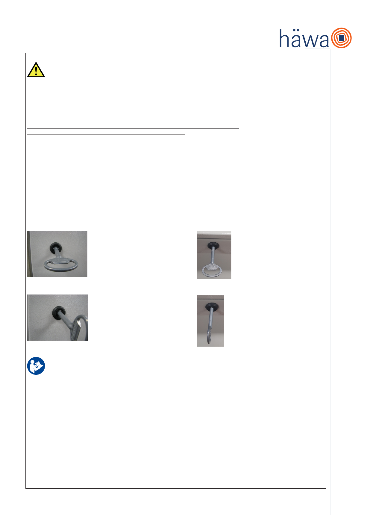
zusätzliche Sicherung durch Gurte o. ä. – sicher, dass das Produkt nicht kippt. Achten Sie darauf, das bei offener Pultplatte die Aufhalteschere gemäß der
Abbildung vollständig eingerastet ist, bevor Sie im Gehäuse arbeiten durchführen.
Beachten Sie ebenfalls die Anleitungen für das Zubehör.
Drehmomentangaben sind einzuhalten.
Zum Erhalt der jeweiligen Schutzart (IP) sind alle Öffnungen im Gehäuse mit Betriebsmittel mindestens derselben Schutzart fachgerecht zu verschließen
(siehe Hinweise für die Aufstellung).
Sichern Sie bestückte Montageplatten, Schwenkrahmen und sonstige Einbauten beim Transport.
Für die Tür(en), Pultplatte sowie die Kabelplatte im Boden ist ein Potenzialausgleich konstruktiv vorhanden. Als zusätzliche Maßnahme für einen der Anwen-
dung angepassten Potenzialausgleich sind die Tür(en), der Pultplatte und der Korpus mit Schutzleiterbolzen ausgestattet.
Stellen Sie sicher, dass die Umgebungstemperaturen am Aufstellort -25 °C und +40 °C nicht unter-/ überschreiten, kein grober Schmutz und starke Feuchte
vorhanden sind und das Produkt waagrecht steht.
Stellen Sie sicher, dass Türen vollständig geschlossen sind (siehe Hinweise für die Aufstellung).
Die auf Seite 5 angegebenen maximalen statischen Belastungen dürfen nicht überschritten werden.
Werden Gehäuse H335 als Enclosures for Electrical Equipment UL50/UL50E bzw. Industrial Control Panels UL508A verwendet gilt folgender Zusatz:
Beachten Sie die für ihre Niederspannungs-Schaltgerätekombination / enclosed industrial control panel geltenden Normen und Vorschriften in
Verbindung mit den unter Pkt. 1 Bestimmungszweck angegebenen möglichen Type Ratings. Beachten Sie ebenfalls die Anleitungen für das
Zubehör. Verschließen Sie sämtliche Öffnungen fachgerecht mit Geräten / Betriebsmitteln mit geeigneten Type Ratings.
Stellen Sie sicher, dass der Schaltschrank spannungsfrei geschaltet ist und sichern Sie diesen gegen versehentliches Wiedereinschalten ab.
4. Vorhersehbare Fehlanwendung, verbleibende Restgefahren
Vorhersehbare Fehlanwendung:
• Die Last ist beim Bewegen (Transport, Aufstellung) nicht gegen Herunterfallen, Kippen gesichert.
• Es befinden sich während des Transports oder Verbringens an den Aufstellort mehr Personen als notwendig im Gefahrenbereich.
• Der Aufstellort ist verschmutzt. Einsatzbedingungen und Verwendung widersprechen der bestimmungsgemäßen Verwendung.
• Kein Ausrichten, falsche Auswahl von Befestigungsmittel, Verwenden von ungeeignetem Werkzeug.
• Qualifikation von Personen nicht ausreichend.
• Sicht-/Funktionsprüfungen werden nicht durchgeführt.
• Reinigung erfolgt nicht.
• Es werden keine Original-Ersatzteile verwendet.
• Aufhalteschere nicht vollständig eingerastet
Die nach einer Risikoanalyse verbleibenden Restgefahren können sein:
• Quetschen, Stoß durch kippende, fallende Teile,
• Schneiden an scharfen Kanten,
• Ausrutschen, Stürzen auf verschmutzten, feuchten, glatten Böden und
• elektrischer Schlag.
Diese Restgefahren können durch aufmerksames Arbeiten und vom Betreiber vorgesehene (Schutz-) Maßnahmen vermieden werden.
Vorhersehbare Fehlanwendung:
Werden Gehäuse H335 als Enclosures for Electrical Equipment UL50/UL50E bzw. Industrial Control Panels UL508A verwendet gilt folgender Zusatz:
- Ausgewählte Betriebsmittel sind nicht UL-zugelassen oder besitzen ein ungeeignetes Type Rating
5. Hinweise für den Transport
Das Produkt ist – vorzugsweise auf Palette – stehend zu transportieren. Bei Einzeltransport, ohne Einbauten (ausgenommen Montageplatte auf
der Rückwand) und unbelasteter Türe, auch auf der Rückwand flach liegend. Das Produkt muss während des Transports durch geeignete
Maßnahmen gegen Kippen gesichert werden (Lastverteilung, Schwerpunkt beachten).
In Kurven, unabhängig vom Transportmittel, langsam transportieren. Kippgefahr bei hohen oder kopflastigen Gehäusen.
Verwenden Sie Gurte oder Transportbänder so, dass Türen oder die Pultplatte nicht punktuell belastet werden. Es besteht die Gefahr der Beschädigung der
PU-Dichtung.
Achten Sie auf eine saubere Umgebung um evtl. Stürzen, Ausrutschen zu vermeiden.
Verwenden Sie angemessene Schutzausrüstung (z.B. Handschuhe, Sicherheitsschuhe).
Gehäuse mit montierten Sockeln/Füßen (Zubehör) sind grundsätzlich mittels Palette zu transportieren oder anzuheben.
Sichern Sie bestückte Montageplatten gegebenenfalls durch zusätzliche Maßnahmen.
Verriegeln Sie die Verschlüsse von Schwenkrahmen.

4
6. Hinweise für die Aufstellung und den (Innen-)Ausbau
Passen Sie den Türanschlag an notwendige Fluchtwege an!
Das Produkt muss während des Auspackens und Aufstellens durch geeignete Maßnahmen gegen Kippen oder Herabfallen gesichert werden
(Lastverteilung, Schwerpunkt beachten).
Prüfen Sie das Produkt vor dem Aufstellen auf Beschädigungen.
Achten Sie auf eine saubere Umgebung, um Stürzen, Ausrutschen zu vermeiden.
Verwenden Sie angemessene Schutzausrüstung (z.B. Handschuhe, Sicherheitsschuhe).
Gebrauchslage: stehend.
Erfolgt der (Innen-)Ausbau bei auf dem Rücken liegendem Gehäuse, ist/sind die Tür(en) vorher zu demontieren.
Alternativ können Türen bei maximal 180° Öffnungswinkel sicher abgestützt werden.
Eine waagrechte Aufstellung ist Voraussetzung für den Erhalt der IP-Schutzart.
Achten Sie darauf, dass die Sicherung der Pultplatte gemäß der Abbildung vollständig eingerastet ist bevor Sie im Gehäuse Arbeiten durchführen.
Die Pulte und eventuell untermontierte Sockel (Zubehör) sind für das Verschrauben am Boden konzipiert.
Treffen Sie bei der Verwendung von Nivellierfüßen (Zubehör) gegebenenfalls Maßnahmen gegen Kippen. Zusätzlich sind in Abhängigkeit der Breite / Tiefe
und des Gesamtgewichts eventuell Verstärkungen (Zubehör) zwischen den Nivellierfüßen und dem Pultbodenboden / Sockel zu montieren.
Vorhandene oder vor Ort hergestellte Ausbrüche und Bohrungen sind mit Geräten oder sonstigen Einbauteilen in mindestens der IP-Schutzart des Pultes
fachmännisch zu verschließen.
Vor Inbetriebnahme sind die mechanischen Funktionen des Pultes, insbesondere das Schließen der Tür und der Pultplatte zu prüfen. Für die Schutzart rele-
vante Dichtungen sowie der Schutzleiter sind einer Sichtprüfung zu unterziehen.
Verwenden Sie zum Verschließen der nicht benötigten Bohrungen auf, der Zarge die beiliegenden Kunststoffstopfen (siehe Beipack).
Die Stellung des Betätigungseinsatzes (Standard: 3 mm Doppelbart) zeigt an, ob die Tür/Pultplatte sicher verschlossen ist.
Geschlossen: Tür(en): 90° zur nächstliegenden Türaußenkante. Geschlossen: Pultplatte: parallel zur Pultplatte
Offen: Tür(en): Parallel zur nächstliegenden Türaußenkante. Offen: Pultplatte: 90° zur Pultplatte
Werden Gehäuse H335 als Enclosures for Electrical Equipment UL50/UL50E bzw. Industrial Control Panels UL508A verwendet gilt folgender Zusatz:
Eine waagrechte Aufstellung ist Voraussetzung für den Erhalt des jeweiligen Type Ratings. Sämtliche vorhandenen oder vor Ort hergestellte
Öffnungen sind in geeigneter Weise zu verschließen. Wir verweisen grundsätzlich auf die UL 508A, 19 Enclosure Openings.
Beachte:
Bei Verwenden des Type Rating 2 ist eine Ablaufbohrung Ø3,2 bis Ø6,4mm oder eine geeignete Drainage im Boden einzubringen
7. Hinweise für die Inspektion, Wartung, Instandsetzung
Bitte prüfen Sie, gegebenenfalls im Rahmen der vom Betreiber festgelegten Revision, mindestens 1 x jährlich:
• den Verschluss und die Scharniere auf Beschädigungen, festen Sitz und einwandfreie Funktion,
• Dichtungen von Türen, Pultplatte, Kabelplatten auf Beschädigung und ob diese ohne Spalte anliegen,
• die Oberfläche auf Beschädigung und auf nicht verschlossene Bohrungen (führt gegebenenfalls zum Verlust der IP-Schutzart) und
• den einwandfreien Zustand der Befestigung.
Passen Sie die Wartungsintervalle an die Umgebungs- und Einsatzbedingungen an!
Säubern Sie das Gehäuse in regelmäßigen Abständen, insbesondere verschmutzte Beschlagteile, um Schwergängigkeit und Fehlfunktion zu vermeiden.
Beschlagteile sind bei Bedarf mit geeigneten Schmiermitteln zu behandeln.
Tauschen Sie beschädigte Teile aus und verwenden Sie nur häwa Originalteile. Kleinere Beschädigungen von lackierten Oberflächen wie Kratzer können
mit dem häwa Ausbesserungslack für RAL 7035, Art-Nr. 3080-7035-03-75 repariert werden.
Geben Sie bei der Beschaffung von Ersatzteilen – zu deren Identifizierung – die Artikelnummer des Schrankes und die Auftragsnummer an – siehe Innenseite Tür.

5
Werden Gehäuse H335 als Enclosures for Electrical Equipment UL50/UL50E bzw. Industrial Control Panels UL508A verwendet gilt folgender Zusatz:
Für die Beschaffung von Ersatzteilen nennen Sie bitte zusätzlich das verwendete Type Rating des Gehäuses.
8. Technische Daten
Statische Belastungen:
Maximale Belastung inklusive Gehäusegewicht: darüber hinaus: 4.000 N
Maximale Belastung der Montageplatte: ungekantet 2.000 N
gekantet 3.000 N
Maximale Belastung der Tür 180°: 2 Scharniere 50 N
Maximale Belastung der Pultplatte: bis B=799mm 250 N
ab B=800mm 500 N
Anmerkung:
Sämtliche Angaben gelten:
a) unter der Maßgabe der gleichmäßigen Lastverteilung auf der Fläche bzw. im Raum.
IK-Schutzgrad: IK08
IP-Schutzgrad: IP54
Werden Gehäuse H335 als Enclosures for Electrical Equipment UL50/UL50E bzw. Industrial Control Panels UL508A verwendet gilt folgender Zusatz:
UL Type Rating
Type 1, 2*, 5, 12
*: Siehe Pkt. 6. Hinweise für die Aufstellung und den (Innen-)Ausbau
Angaben zum Drehmoment:
Unten stehende Angaben wurden einmalig an Seriengehäusen mit Standardlackierung ermittelt und stellen unter optimalen Bedingungen (beispiels-
weise gerades Ansetzen gewindeformender Schrauben) verbindliche Werte dar.
• Kabelplatte
Befestigen der Kabelplatte gemäß Lieferumfang am Korpus: 2 Nm
• Montageplatte glatt und gekantet
Befestigen/Kontern der Montageplatte: 10 Nm
• Verschluss (nach Anschlagwechsel der Türe)
Befestigen des Verschlussgehäuses an Türblech (Mutter SW 27): 6 Nm
Befestigen der Schließzunge an Verschlussgehäuse (Schraube M6): 6 Nm
• Scharniere (nach Anschlagwechsel der Türe)
Befestigen Scharnierbock: 3,5 Nm
• Schutzleiter
Befestigen des Schutzleiterkabels/-bands an Schutzleiterbolzen: 9 Nm
Sämtliche technische Daten wurden an Produkten Standpult H335 einmalig ermittelt.
9. Zubehör
Passendes Zubehör finden Sie unter http://www.haewa.de/loesungen-produkte/schranksysteme.html
Eine Montageanleitung liegt dem Zubehör bei – sofern nicht selbsterklärend.
10. Gewährleistung
Es gelten unsere AGB: http://www.haewa.de/unternehmen/impressum.html.
Für Druckfehler übernehmen wir keine Haftung.
11. Service
Die für ihren Ort zuständige Vertriebsniederlassung finden Sie auf der letzten Seite.
Service-Rufnummer: Tel.: +49 7353 984 60

6
Contents
1. Intended Purpose
2. General Information
3. Safety Instructions
4. Foreseeable Misuse, Residual Risks
5. Instructions for Transport
6. Instructions for Installation and (Interior) Fittings
7. Instructions for Inspection, Maintenance, Repair
8. Technical Data
9. Accessories
10. Warranty
11. Service
Please play special attention to the parts of these instructions which are underlined, printed in bold or provided with the warning sign!
1. Intended Purpose
Consoles type H335 are designed for use on machinery and low-voltage switchgear and control-gear assemblies. They are suitable for housing electrical and
mechanical components and devices for industrial application and can be mounted individually on the floor, in front of a wall or free-standing.
They are not intended to be carried by hand. Access to the interior is effected through doors, removable covers, cover plates or similar items provided, locka-
ble by key or a tool. Enclosures can be used by individuals or several people.
Designed in compliance with DIN EN 62208 for indoor installation, in a normal industrial environment, this type is protected against dust and powerful water
jets with a maximum protection of IP54 – see Safety Instructions for more details.
In the case of special operating conditions being in place as per DIN EN 62208, 7.3, special agreements must be made with the manufacturer!
H335 consoles are not designed for dynamic loads or use in ex areas.
If consoles H335 are used as Enclosures for Electrical Equipment UL50/UL50E or Industrial Control Panels UL508A the following addition
applies:
Consoles H335 are designed for installation and use of electrical equipment in non-hazardous environments and enclosures for control systems
for general industrial use with an operating voltage of 1000V or less at a maximum ambient temperature of 40°C (104°F). Based on
UL 50 / UL 50E and UL approval E90604, the cabinets are designed for protection classes corresponding to Type Ratings 1, 2, 5 and 12.
2. General Information
These instructions are an integral part of the product.
They are meant for skilled persons in industry and trade and for instructed persons to equip, set up and connect control cabinets in compliance with the
applicable standards.
Please keep them in a safe place for future reference. The same applies to assembly and operating instructions for accessories.
We do not accept liability for any damage caused to or by users or third parties resulting from non-observance of these instructions and /or abnormal use.
The instructions are constantly reviewed and updated if necessary (subject to technical changes) –
see http://www.haewa.de/dialog-kontakt/download-center.html
The declaration of conformity can be obtained upon request from our sales office.
You will find the product descriptions on our website or in the cabinet systems catalog under the respective order number.
Note: Information included in the print media you have may not be up to date any more. In case of doubt, the information given on our website shall apply.
The scope of delivery includes:
• 1 console with door(s) and console plate
• Accessories with description of contents
• 1 key, 3 mm double-mandrel actuation
• pre-mounted cable entry and mounting plates
All details given apply to an empty cabinet without further adaption.
You will find the accessories that match the selected enclosure size on our website. (Type in order number of your product and click on tab “Accessories“).
The accessories that are recommended or necessary for certain cases are specified in these instructions with their oder numbers.

7
3. Safety Instructions
The instructions on foreseeable misuse and residual risks as well as the special instructions and technical data specified on pages 7 to 9 of these
instructions must be observed under all circumstances to reduce danger to life and limb as much as possible.
Please take note of the standards and regulations applicable to your low-voltage switchgear and control-gear assembly.
For any transport including moving to the installation site and unpacking as well as when completing the interior or any (later) work, take suitable safety
measures, if necessary by additionally fixing it with straps or similar, to secure the product against tipping. Please make sure that the scissor action struts are
fully engaged as shown in the illustration when the console plate is open before performing any work in the console.
The instructions for accessories must also be observed.
Torque specifications must be adhered to.
To maintain the protection class (IP) specified, all openings in the cabinet must be properly closed using devices of at least the same protection class.
Secure fitted mounting plates, swing frames and other interior fittings for transport (see installation instructions).
The design features include equipotential bonding for the door(s), the console plate and the cable entry plates at the bottom. As an additional equipotential
bonding measure adapted to the application, the door(s), console plate and the body are fitted with protective ground studs. Ensure that the ambient tempe-
ratures at the installation site do not fall below -25 °C or exceed +40 °C, that there is no coarse dirt and excessive moisture and that the product stands level.
Make sure that the doors are fully closed (see installation instructions).
The maximum static loads as specified on page 9 must not be exceeded.
If the consoles type H335 are used as Enclosures for Electrical Equipment UL50/UL50E or Industrial Control Panels UL508A the following additionapplies:
Please observe the standards and regulations applicable to your low-voltage switchgear combination / enclosed industrial control panel in
conjunction with the possible Type Ratings specified under item 1 Intended purpose. Please also follow the instructions for the accessories.
Properly close all openings with devices / equipment with suitable Type Ratings.
Ensure that the console is disconnected from the power supply and secure it against accidental reconnection
4. Foreseeable Misuse, Residual Risks
Foreseeable misuse:
• The load is not secured against falling, tipping over when moved (transport, set-up).
• More people than necessary are present in the danger zone during transport and movement to the installation site.
• The installation site is polluted. Operating conditions and usage do not comply with the intended use.
• No alignment, wrong selection of mounting hardware, use of inappropriate tools.
• Insufficient qualification of staff.
• Visual inspections and functional tests are not carried out.
• No cleaning is effected.
• Spare parts other than original parts are used.
• Scissor action struts are not fully engaged.
The residual risks remaining after a risk analysis may be as follows:
• Crushing or impacts from tipping or falling objects,
• Cutting at sharp edges,
• Slipping, falling on dirty, wet, slippery floors and
• Electric shock.
These residual risks can be avoided by working attentively and implementing protective measures as provided by the operator.
Foreseeable misuse:
If consoles type H335 are used as Enclosures for Electrical Equipment UL50/UL50E or Industrial Control Panels UL508A the following addition applies:
- Selected equipment is not UL listed or has no matching Type Rating.
5. Instructions for Transport
The product must be transported in an upright position – preferably on a pallet. When transported individually without interior fittings (with the
exception of the mounting plate at the rear plate) and with no load on the door, the enclosure can also be moved lying flat on the back. During
transport, the product must be suitably secured against tipping over – attention must be paid to load distribution, center of gravity.
In curves, enclosures must be moved slowly, irrespective of the means of transport. A tip-over hazard exists for tall or top-heavy enclosures.
Use straps or transport belts so as to avoid point loads on the doors or console panel. There is a risk of damaging the PU seal.
Pay attention to a clean working environment to avoid slipping and/or falling.
Use appropriate protective equipment (e.g. gloves, safety shoes).
If bases are mounted underneath the enclosures (accessories), they must always be transported or lifted on a pallet.
Secure fitted mounting plates through additional measures, if necessary.
Secure the locks of swing frames.

8
6. Instructions for Installation and Interior Fittings
Adjust the door hinge according to any necessary escape routes.
During unpacking and installation, suitable measures must be taken to secure the product against tipping over (attention must be paid to load distribution,
center of gravity).
Prior to installation, check the product for any damage.
Pay attention to a clean working environment to avoid slipping and/or falling.
Use appropriate protective equipment (e.g. gloves, safety shoes).
Position when in use: upright
If the interior is completed with the enclosure lying on its back, the door(s) must be removed beforehand. Alternatively, doors can be securely supported at
an opening angle of max. 180°.
Horizontal installation is a requirement for maintaining the IP protection class.
Make sure that the console plate safety device is fully engaged as shown in the illustration before performing any work in the console.
The consoles and the bases mounted underneath, if applicable, (accessories) are designed for screwing into the floor.
When using leveling feet (accessories), take measures to prevent tipping if necessary.
In addition, depending on the width / depth and overall weight, reinforcement brackets (accessories) must be installed between the leveling feet and the
bottom of the console / base, if necessary.
Existing openings or drill holes or those made at the site must be properly closed with devices or other fittings that are at least of the same IP protection class
as the console.
Prior to putting the console into service, the mechanical functions of the console must be checked, in particular if the door and the console plate close pro-
perly. A visual inspection of the seals which are relevant for maintaining the protection class as well as of the protective conductor must be carried out.
For closing the unused holes in the frame, use the enclosed plastic plugs (see accessory pack).
The position of the key (standard: 3 mm double-mandrel) indicates if the door/console plate is securely locked.
Closed: door(s): 90° to the nearest external door edge. Closed: console plate: Parallel the console plate
Open: door(s): parallel to the nearest external door edge. Open: console plate: 90° to the console plate
If consoles type 335 are used as Enclosures for Electrical Equipment UL50/UL50E or Industrial Control Panels UL508A the following addition applies:
Horizontal installation is a prerequisite for maintaining the respective Type Ratings
.
All existing openings or openings made on site must be closed in a suitable manner. We generally refer to UL 508A, 19 Enclosure Openings.
Note:
When using Type Rating 2 or 3R, a Ø3.2 to Ø6.4mm drain hole or suitable drainage shall be provided in the bottom.
7. Instructions for Inspection, Maintenance and Repair
Please check at least once a year, in the framework of the inspection as determined by the operator, as appropriate:
• lock and hinges for damage, stability and proper functioning,
• seals of doors, console plate, cable plates for damage and whether they fit without gaps,
• surface finish for damages and that all drillings are closed (which might lead to loss of the IP protection class),
• the perfect state.
Adjust maintenance intervals to the ambient and operating conditions!
Clean the enclosure in regular intervals, in particular contaminated fittings, to avoid sluggishness and malfunctions. If necessary, fittings must be treated with
suitable lubricants.
Exchange damaged parts and use original häwa parts only. Minor flaws on painted surfaces such as scratches can be fixed using the häwa touch-up paint
for RAL 7035, order no. 3080-7035-03-75.
When purchasing spare parts please state the cabinet product code and your order number to ensure identification – see inside of door.

9
If consoles type H335 are used as Enclosures for Electrical Equipment UL50/UL50E or Industrial Control Panels UL508A the following addition applies:
For the procurement of spare parts, please also state the Type Rating used for the console.
8. Technical Data
Static loads:
Maximum load including console weight: Furthermore: 4.000 N
Maximum load of mounting plate: not flanged 2.000 N
flanged 3.000 N
Maximum load of door 180°: 2 hinges 50 N
Maximum load on console plate: up to W=799mm 250 N
from W=800mm 500 N
Notes:
All specifications apply:
a) provided the load is evenly distributed on the surface or in the space.
IK protection class: IK08
IP protection class: IP54
If consoles type H335 are used as Enclosures for Electrical Equipment UL50/UL50E or Industrial Control Panels UL508A the following additionapplies:
UL Type Rating
Type 1, 2*, 5, 12
*: See item 6. Instructions for Installation and Interior Fittings
Torque specifications:
The specifications stated below have been uniquely determined for standard sheet steel cabinets with standard finish and for stainless-steel cabinets
and are deemed to be binding under optimum conditions (e.g. straight fitting of thread-forming screws).
• Cable entry plate
Attachment of the cable entry plate according to scope of delivery to body: 2 Nm
• Mounting plate flanged or not flanged
Attachment / countering of the mounting plate: 10 Nm
• Lock (after changing the opening direction of the door)
Attachment of the lock housing to the door panel (nut SW 27): 6 Nm
Attachment of the latch to the lock housing (screw M6): 6 Nm
• Hinges (after changing the opening direction of the door)
Attachment of the hinge bracket: 3.5 Nm
• Protective ground conductor
Attachment of the protective ground conductor cable/tape to the protective conductor stud: 9 Nm
All technical specifications have been determined once on products console H335.
9. Accessories
You will find suitable accessories under http://www.haewa.com/solutions-products/enclosures.html
Assembly instructions are enclosed with the accessories unless self-explanatory.
10. Warranty
These instructions are subject to our General Terms and Conditions: http://www.haewa.com/company/imprint.html.
We do not accept liability for printing errors.
11. Service
You will find the location of the sales office responsible for your area on the last page.
Service phone number: +49 7353 98460

10
Sommaire
1. Utilisation prévue
2. Généralités
3. Consignes de sécurité
4. Cas d’utilisation incorrecte prévisible, risques résiduels
5. Consignes de transport
6. Consignes d’installation et de montage (intérieur)
7. Consignes pour l’inspection, la maintenance et la remise en état
8. Caractéristiques techniques
9. Accessoires
10. Garantie
11. Service
Dans cette notice de montage et d’utilisation, veillez particulièrement aux passages soulignés, en caractère gras ou étant précédés ou
accompagnés du pictogramme d‘avertissement ci-contre !
1. Utilisation prévue
Les pupitres type H335 sont conçues pour l’utilisation avec des machines et ensembles d’appareillage à basse tension. Ils sont appropriés à recevoir des
composants, appareils électriques et mécaniques de l‘industrie et peuvent être installées individuellement, devant un mur ou de façon isolée pour être fixées
au sol. Ils ne sont pas destinés à être portés à la main. L’accès à l’intérieur s’effectue par des portes, bandeau de pupitres, revêtements ou pièces analogues
prévues à cet effet. Ils se ferment à clé ou par un autre outil. Les pupitres peuvent être utilisés par une ou plusieurs personnes.
Conçue selon DIN EN 62208 pour une utilisation à l‘intérieur, dans un environnement industriel normal, la version avec IP54 maximum est protégée contre la
poussière et contre de forts jets d’eau – voir également les consignes de sécurité.
En présence de conditions de fonctionnement particulières selon DIN EN 62208, 7.3, il faudra convenir d’un accord particulier avec le fabricant ! Le pupitre
H335 n’est pas conçu pour des charges dynamiques ou pour une application en atmosphère Ex.
Lorsque les pupitres type H335 sont utilisés comme pupitres pour équipement électrique UL50/UL50E ou comme des panneaux de commande
industrielles UL508A, l‘ajout suivant s‘applique :
Les pupitres type H335 sont conçus pour l‘installation et l‘utilisation d‘équipements électriques dans des environnements non dangereux et des
pupitres pour systèmes de contrôle pour l‘utilisation industrielle générale avec une tension de service de 1000V ou moins à une température
ambiante maximale de 40°C (104°F). Basés sur les normes UL 50 / UL 50E et sur l‘approbation UL E90604, les pupitres sont conçus pour des
indices de protection correspondant Type Ratings 1, 2, 5 et 12.
2. Généralités
Cette notice fait partie intégrante du produit.
Elle s’adresse aux spécialistes qualifiés de l’industrie et de l’artisanat et aux personnes initiées à l’électronique, pour équiper, installer et raccorder des ar-
moires de commande conformément à la norme.
Veuillez conserver cette notice soigneusement tout comme les notices de montage et d’utilisation des accessoires.
En cas de non-respect de cette notice et d’une utilisation non-conforme du produit, nous déclinons toute responsabilité en cas d‘éventuels dommages
causés aux ou par les utilisateurs ou aux tiers.
Cette notice est vérifiée en permanence et le cas échéant actualisée (sous réserve de modifications techniques) –
voir http://www.haewa.fr/dialogue-contact/telechargement.html
Sur demande, vous obtiendrez la déclaration de conformité auprès de votre succursale de distribution.
Vous trouverez la description du produit sur notre site internet ou dans le catalogue Systèmes d’armoire sous la référence correspondante.
Note : il est possible que les informations que vous trouverez dans la presse écrite ne soient plus actuelles. En cas de doute, reportezvous aux
informations sur notre site web.
La livraison comprend :
• 1 pupitre avec porte(s) et bandeau
• Accessoires avec description du contenu
• 1 clé, double-barre 3 mm
• Plaque d’entrée de câbles et platine de montage prémontées
Toutes les informations s’appliquent au coffret vide sans autre traitement.
Vous trouverez les accessoires adaptés à la taille du coffret sélectionné sur notre site internet (entrez la référence de votre produit et sélectionnez l’onglet «
Accessoires »). Les accessoires recommandés ou nécessaires à certains cas d’application sont indiqués dans cette notice avec la référence correspondante.

11
3. Consignes de sécurité
Les consignes concernant l’utilisation incorrecte prévisible et les risques résiduels, mais aussi les consignes spécifiques et les caractéristiques
techniques des pages 11 à 13 de cette notice sont à respecter pour éviter de mettre en danger la vie et la santé de l’utilisateur ou d’un tiers.
Tenez compte des normes et réglementations en vigueur pour les ensembles d’appareillage à basse tension.
Lors du transport, de la pose sur le lieu d’installation, du déballage, de l’équipement intérieur et de la transformation (ultérieure), assurez-vous par des
mesures appropriées que le produit ne bascule pas – par une fixation supplémentaire au moyen de sangles ou d’attaches par exemple. Lorsque le pupitre est
ouvert, veillez à ce que les systèmes d‘arrêt soient complètement engagés comme indiqué sur l‘illustration avant d‘effectuer des travaux dans le pupitre.
Respectez les instructions pour les accessoires, mais aussi les spécifications concernant les couples de serrage.
Pour maintenir la classe de protection respective (IP), fermez correctement toutes les ouvertures dans le coffret par du matériel possédant au moins le même
indice de protection (voir consignes d’installation).
Lors du transport, veillez à sécuriser les plaques de montage équipées, les cadres pivotants et les autres équipements.
Pour la(les) porte(s) et le bandeau de pupitre ainsi que pour les plaques de câbles dans le sol, il existe côté construction une liaison équipotentielle. En tant
que mesure supplémentaire pour une liaison équipotentielle adaptée à l’application, la(les) porte(s), le bandeau du pupitre ainsi que le châssis sont équipés
de goujons de mise à la terre. Assurez-vous que la température ambiante sur le lieu d’installation soit comprise entre -25 °C et +40 °C, qu’il n’y ait pas de
saleté grossière ni de forte humidité et que le produit soit horizontal.
Assurez-vous que les portes soient complètement fermées (voir consignes d’installation).
Les charges statiques maximales indiquées en page 13 ne doivent pas être dépassées.
Lorsque les pupitres type H335 sont utilisés comme pupitres pour équipement électrique UL50/UL50E ou comme panneaux de commande
industrielles UL508A, l‘ajout suivant s‘applique :
Veuillez respecter les normes et réglementations applicables à votre unité d‘appareillage à basse tension / tableau de commande industriel inclus en
conjonction avec les indices de protection Type Ratings spécifiées au point 1 Veuillez également respecter les instructions relatives aux accessoires.
Fermez toutes les ouvertures proprement avec des dispositifs/équipements avec des indices de protection Type Ratings convenables.
Assurez-vous que le pupitre est déconnecté du réseau et protégez-le contre toute reconnexion accidentelle.
4. Cas d’utilisation incorrecte prévisible, risques résiduels
Cas d’utilisation incorrecte prévisible :
• Lors de son déplacement (transport, mise en place), la charge n’est pas stabilisée contre un basculement ou une chute.
• Au cours du transport ou sur le lieu d’installation, il y a plus de personnes que nécessaire dans la zone de danger.
• Le lieu d’installation est encrassé. Les conditions d’application et l’utilisation sont en contradiction avec l’utilisation conforme à sa destination.
• Aucun ajustement, mauvais choix des moyens de fixation, utilisation d’outils inappropriés.
• Qualification du personnel insuffisante.
• Contrôles visuels et de fonctionnement n’ont pas été réalisés.
• Le nettoyage n’a pas eu lieu.
• Les pièces de rechange utilisées ne sont pas des pièces d’origine.
• Les systèmes d’arrêt ne sont pas complètement engagés.
Les dangers résiduels demeurant existants après une analyse des risques peuvent être :
• Ecrasement, choc par des pièces renversées ou tombées,
• Coupure à des angles vifs,
• Dérapage, chute sur des sols sales, mouillés et glissants,
• Electrisation.
Ces dangers résiduels peuvent être évités par un travail attentif et des mesures (de protection) prévues par l’exploitant.
Utilisation incorrecte prévisible :
Lorsque les pupitres type H335 sont utilisés comme pupitres pour les équipements électriques UL50/UL50E ou les panneaux de contrôle
industriels UL508A, l‘ajout suivant s‘applique :
- L‘équipement sélectionné n‘est pas approuvé par UL ou possède un indice de protection Type Rating inapproprié
5. Consignes de transport
Le produit est à transporter debout – de préférence sur une palette. En cas de transport isolé sans composant encastré (excepté la plaque de
montage sur la paroi arrière) et avec portes sans charge, il peut être transporté également à plat sur la paroi arrière. Le produit doit être sécurisé
contre le basculement par des mesures adéquates (répartition des charges, respect du centre de gravité).
Dans les virages, transportez les coffrets lentement, indépendamment du moyen de transport. En présence de coffrets hauts et très chargés à l’avant, il y a un
risque de basculement.
Utilisez des sangles ou des bandes de transport qui n’exercent pas de charge ponctuelle sur les portes. Il y a un risque de dégradation des joints PU.
Veillez à un environnement propre pour éviter d’éventuels dérapages ou chutes.
Utilisez un équipement de protection adéquat (gants, chaussures de sécurité p.ex.)
De façon générale, les coffrets avec socle/ pieds montés (accessoires) sont à transporter ou à soulever au moyen d’une palette.
Le cas échéant, les plaques de montage équipées doivent être sécurisées par des mesures supplémentaires.
Verrouillez les fermetures des cadres pivotants.

12
6. Consignes d’installation et de montage (intérieur)
Adaptez le sens d’ouverture des portes aux issues de secours nécessaires !
Pendant le déballage et l’installation, le produit doit être sécurisé contre un basculement et une chute par des mesures adéquates (respectez la répartition
des charges et le centre de gravité).
Vérifiez si le produit est éventuellement endommagé avant l’installation.
Veillez à un environnement propre pour éviter d’éventuels dérapages ou chutes.
Utilisez un équipement de protection adéquat (gants, chaussures de sécurité p.ex.).
Position d’utilisation : debout.
Si l’aménagement intérieur s’effectue avec un coffret couché sur le dos, il faudra auparavant démonter la (les) porte(s). Un angle d’ouverture maximum de
180° permet également de stabiliser la (les) porte(s) en toute sécurité.
Une mise en place horizontale est indispensable au maintien de la classe de protection IP.
Veillez à ce que le dispositif de sécurité du bandeau de pupitre soit complètement engagé comme indiqué sur l‘illustration avant d‘effectuer des travaux dans le pupitre.
Les pupitres tout comme les socles éventuellement montés en dessous sont conçus pour un vissage au sol.
Si vous utilisez des pieds de nivellement, prenez des mesures adéquates contre le basculement. De plus, en fonction de la largeur / la profondeur et du poids
total, il faudra éventuellement monter des renforts (accessoires) entre les pieds de nivellement et le fond de l‘armoire / le socle.
Les découpes et perçages déjà existants ou réalisés sur place sont à fermer correctement par des appareils ou autres pièces en respectant la classe de
protection IP minimum du pupitre.
Avant la mise en service, vérifiez les fonctions mécaniques du pupitre, en particulier la fermeture de la porte et du bandeau. Les joints concernés pour le
maintien de la classe de protection et le conducteur de protection doivent être soumis à un contrôle visuel.
Veuillez utiliser les bouchons en plastique fournis pour fermer les trous non utilisés sur le châssis (voir pièces jointes).
La position de l’axe de fermeture (standard : double-barre 3 mm) montre si la porte/le bandeau est bien fermé(e).
Fermé : porte(s) : 90° vers le bord extérieur de la porte le plus proche. Fermé : bandeau : parallèle au bandeau
Ouvert : porte(s) : parallèles vers le bord extérieur de la porte le plus proche. Ouvert : bandeau : 90° au bandeau
Si les pupitres H335 sont utilisés comme pupitres pour équipement électrique UL50/UL50E ou panneaux de contrôle industriels UL508A, l‘ajout
suivant s‘applique :
Le montage horizontal est obligatoire pour obtenir la classification de Type Ratings correspondante.
Toutes les ouvertures existantes ou percées sur site doivent être fermées de manière appropriée. Nous nous référons généralement à la norme
UL 508A, 19 Enclosure Openings.
Note :
En cas d‘utilisation de la classification de Type Ratings 2, un trou de drainage de Ø3,2 à Ø6,4 mm ou un drainage approprié doit être prévu dans le sol.
7. Consignes pour l’inspection, la maintenance et la remise en état
Veuillez vérifier au moins 1 x par an – le cas échéant dans le cadre d’une révision fixée par l’exploitant :
• le bon état de la fermeture et des charnières (éventuelles dégradations), leur bonne fixation et fonctionnement impeccable
• joints des portes, du pupitre, des plaques de câbles s‘ils sont endommagés et s‘ils sont en contact sans fentes,
• le parfait état de la surface n’est pas endommagée et que tous les perçages sont fermés (conduirait également dans le cas contraire à la perte de la
classe de protection) et
• le bon état de la fixation.
Adaptez les intervalles de maintenance aux conditions environnantes et d’utilisation !
Nettoyez le coffret périodiquement, en particulier les charnières encrassées pour éviter un grippage et un mauvais fonctionnement. Au besoin, les
charnières sont à traiter avec des lubrifiants appropriés.
Remplacez les pièces endommagées et utilisez uniquement des pièces d’origine häwa. Vous pouvez réparer des petites détériorations comme les fissures ou
les rayures sur les surfaces laquées par la laque de réparation häwa pour RAL 7035, référence 3080-7035-03-75.
Lors de l’achat de pièces de rechange, indiquez la référence du coffret et le numéro de commande – pour les identifier – voir intérieur de la porte.

13
Si les pupitres H335 sont utilisés comme pupitres pour équipement électrique UL50/UL50E ou panneaux de contrôle industriels UL508A,
l‘ajout suivant s‘applique :
Pour l‘achat de pièces de rechange, veuillez également indiquer la classification de Type Rating utilisée pour le pupitre.
8. Caractéristiques techniques
Charges statiques :
Charge maxi. poids du pupitre inclus : de plus : 4.000 N
Charge maxi. de la platine de montage : pleine 2.000 N
à bords rabattus 3.000 N
Charge maxi. de la porte 180°: 2 charnières 50 N
Charge maxi. du bandeau de pupitre : jusqu‘à L=799 mm 250 N
à partir de L=800 mm 500 N
Note :
Toutes les indications sont applicables :
a) à condition de respecter une répartition régulière des charges sur la surface ou dans la pièce.
Classe de protection IK : IK08.
Classe de protection IP : IP54
Si les pupitres H335 sont utilisées comme pupitres pour équipement électrique UL50/UL50E ou comme panneaux de contrôle industriels UL508A,
l‘ajout suivant s‘applique :
UL Type Rating
Type 1, 2*, 5, 12
* : Voir paragraphe 6. Consignes d’installation et de montage (intérieur)
Indications concernant les couples :
Les indications ci-dessous ont été calculées une fois sur des coffrets de série en tôle d’acier avec peinture standard et en acier inoxydable et elles
constituent dans des conditions optimales (par exemple serrage droit des vis formant des filetages) des valeurs obligatoires.
• Plaque passe câbles
Fixation de la / des plaque(s) passe câbles en fonction du contenu de la livraison sur le corps du pupitre : 2 Nm
• Platine de montage pleine et à bords rabattus
Fixation/contre-fixation de la platine de montage : 10 Nm
• Fermeture (après le changement du sens d’ouverture de la porte)
Fixation du boîtier de fermeture sur la tôle de porte (écrou SW 27) : 6 Nm
Fixation de la came sur le boîtier de fermeture (vis M6) : 6 Nm
• Charnières (après le changement du sens d’ouverture de la porte)
Fixation du support de charnière sur le corps : 3,5 Nm
• Goujon de mise à la terre
Fixation du câble / des bandes de mise à la terre aux goujons de mise à la terre : 9 Nm
Toutes les caractéristiques techniques ont été calculées une fois sur des produits pupitre H335.
9. Zubehör
Vous trouverez les accessoires appropriés sur http://www.haewa.fr/solutions-produits/coffrets-et-boitiers.html.
Une notice de montage est fournie avec l’accessoire – si son montage n’est pas explicite.
10. Garantie
Nos CGV s’appliquent : http://www.haewa.fr/entreprise/mentions-legales.html.
Nous déclinons toute responsabilité pour d’éventuelles erreurs d’impression.
11. Service
Vous trouverez en dernière page les succursales de distribution proches de chez vous.
Numéro d’appel du service clientèle : +49 7353 98460

14

15

häwa GmbH
Industriestraße 12
D 88489 Wain
Tel. +49 7353 98460
www.haewa.de
Änderungen vorbehalten / Specifications subject to modifications / Sous réserve de modifications
SCHRANKSYSTEME
X-FRAME
GEHÄUSE
ZUBEHÖR
KLIMATISIERUNG
LEITUNGSKANÄLE
SONDERBAUTEN
WERKZEUGE
D 08451 Crimmitschau
Sachsenweg 3
Tel. +49 3762 95271/2
D 47167 Duisburg
Gewerbegebiet Neumühl
Theodor-Heuss-Str. 128
Tel. +49 203 346530
A 4020 Linz
Schmachtl GmbH
Pummererstraße 36
Tel. +43 732 76460
CH 8967 Widen
häwa (schweiz) ag
Gyrenstrasse 5a
Tel. +41 43 3662222
D 63477 Maintal
Dörnigheim
Carl-Zeiss-Straße 7
Tel. +49 6181 493031
DK 6400 Sonderborg
Eegholm A/S
Grundtvigs Allé 165 - 169
Tel. +45 73 121212
E 48450 Etxebarri
Hawea Ibérica, s.l.
Poligono Leguizamón
Calle Guipuzcoa, Pab.9
Tel. +34 944 269521
F 67600 Sélestat
häwa France Sarl
22, Rue Roswag
Tel. +33 672 71 3309
I 88489 Wain
häwa Italia
Industriestraße 12
Tel. +49 7353 9846115
NL 7548 CV Enschede
häwa Nederland B.V.
De Plooy 6
Tel. +31 53 4321835
SE 88489 Wain
häwa Schweden
Industriestraße 12
Tel. +49 7353 98460
USA Duluth, GA 30097
haewa Corporation
3768 Peachtree Crest Drive
Tel. +1 770 9213272
SE 19561 Arlandastad
(only for tools)
Nelco Contact AB
Dalens Gata 7
Tel. + 46 875 47040
© häwa, 11/2022 0335-0000-00-77
Table of contents
Languages: