HAWE Hydraulik SE EV1D User manual

Electronic amplifier type EV1D
Assembly instructions
B 7831 D
09-2015-1.3
Modular construction
Supply voltage UB: 10...48 V DC
Output current IA: max. 2 A
© by HAWE Hydraulik SE.
The forwarding and reproduction of this document, as well as the use and communication of its contents, are forbidden unless expressely permitted.
Any breach or infringement will result in liability for damages.
All rights reserved concerning patent or utility model application.

2/8 D 7831/D - EV1D - 09-2015-1.3 © HAWE Hydraulik SE
1Parameters
1.1 General parameters
Connection leads •Max. 1.5 mm
Fastening With a card holder (accessory) on 35 mm standard support rails or 32 mm support rails according to
DIN EN 60715
Installation position Any
Protection class IP 00 according to DIN EN 60529, VDE 0470-1 or IEC 60529
Ambient temperature -20°C...+60°C
1.2 Electrical Data
Supply voltage UB10...48 V DC
Output voltage UAUB- 0.7 V DC, pulse-width modulated
Output current IAmax. 0...2 A short-circuit proof
Setting range Imin = 0...2 A
Imax = 0...2 A
Factory default setting Imin = 0 A; Imax = 2 A
Voltage ranges Unom Can be optionally set as 0...5 V DC or 0...10 V DC
Factory default setting 0...10 V DC
Reference voltage USt 5 V DC ±4%
Nominal volume max. 5 mA (stable voltage for supplying the target value potentiometer)
Enable/disable input TTL compatible or can be triggered with a contact
1.3 Electro-magnetic compatibility (EMC)
The EMC of the device was tested using an accredited testing laboratory (emitted interference according to DIN EN 61000-6-3 and
immunity to interference according to DIN EN 61000-6-2 evaluation criterion "B"). The test set-ups only represent typical use. This EMC
testing does not release the user from carrying out adequate prescribed EMC testing of their complete system (according to Directive
2004/108/EC). If the EMC of the complete system must be further amplied, the following measures can be tested and introduced:
■The required smoothing capacitor in accordance with Chapter 1.2, "Electrical Data" is not only needed to ensure the device functions
correctly, but also to guarantee compliance with EMC guidelines (conducted emitted interference).
■The equipment should be installed in an metal cabinet (shielding)
■Supply lines, such as inputs and outputs to and from the device, should be as short as possible. If necessary they should be shielded
and twisted in pairs (to reduce the antennae-like effect for increasing the immunity to interference).

© HAWE Hydraulik SE D 7831/D - EV1D - 09-2015-1.3 3/8
2Dimensions
All dimensions in mm, subject to change.
2.1 Printed circuit board
Proportional amplier (card) EV1D
X1 + solenoid
X2 + solenoid
X3 Auxiliary inputs, programming interface
Terminal connections:
X1-1 + solenoid
X1-2 - solenoid
X1-3 0 V power (GND)
X1-4 10-48 V supply voltage
X2-1 Enable/block input
X2-2 5V output
X2-3 0...5 V / 0...10 V target value input
X2-4 0 V analogue (GND)
X2-5,
X2-6,
X3
Auxiliary inputs, programming interface
Jumper J1
10 V 5 V

4/8 D 7831/D - EV1D - 09-2015-1.3 © HAWE Hydraulik SE
3Installation, operation and maintenance information
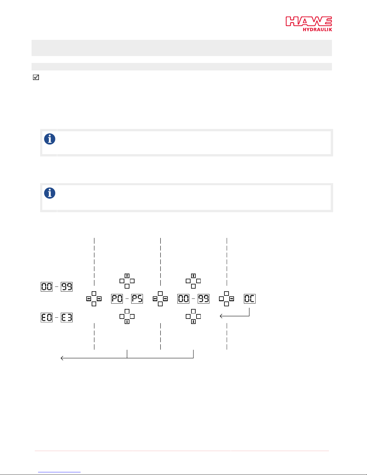
3.1 Information on setting
The card is parameterised using four buttons and a two-digit seven-segment display. All operations are performed using the buttons
arranged in a square. In accordance with the normal installation position of the card (plug connections at bottom), the buttons are
labelled top, bottom, right and left.
Parameters that can be adjusted by the user can be selected by navigating in a menu. These are shown in the display with their
(standardised) values and can be modied at the push of a button. Adjusted parameter values are effective immediately once the
modification is made, so that the user receives immediate feedback on the effects of the setting.
However, nal and permanent adoption requires confirmation (at the push of a button). If this does not take place, the adjustment is
aborted after 10 seconds and all settings are as they were prior to the attempted adjustment.
Navigation
The right and left buttons are used to navigate in the menu. The right button is generally used to go deeper into the menu, whereas the
left button is used to go up one level (back). The up and down buttons are used to increase and reduce values.
User parameters
Parameter Designation min max Default Standardisation
P0 Minimum current Imin 0 99 0 20 mA/increment
P1 Maximum current Imax 0 99 50 20 mA/increment
P2 Ramp time, up Tup 1 99 10 100 ms/increment
P3 Ramp time, down Tdown 1 99 10 100 ms/increment
P4 Dither amplitude l 1 99 0 %
P5 Dither frequency (dither period) f 20 (50) 100 (10) 50 (20) Hz (ms)
Note
Note that the parameter values can only be modied in discrete steps using the keypad. Conversion factors that match physical
values to the respective increments are stated under "Standardisation".
© HAWE Hydraulik SE D 7831/D - EV1D - 09-2015-1.3 5/8
3.2 Setting instructions
Changing the parameters
The amplifier is in normal operation.
1. Press and hold the "right" button.
✓P0 is shown in the display. The amplifier is now in parameterisation mode.
2. Use the "up" and "down" buttons to select a parameter from P0...P4.
3. Press the "right" button to select the displayed parameter.
✓The current standardised numerical value of the parameter is displayed. For the meaning of the numerical value and the parameters,
see
Note
Modifications are effective immediately once the value is changed. However, permanent adoption of the values must be
conrmed rst.
4. Press the "up" or "down" button to modify the value.
5. Press and hold the "right" button to conrm the value.
✓The amplifier acknowledges the adoption of the parameter by briey displaying the value 0C
Note
If modied parameters should not be saved, the change can be discarded by pressing the "left" button.
The amplifier switches back to normal operation.
Normal operation
Error code display
Parameterisation mode
Timeout 10 s
Parameter no.
reduction
Parameter no.
increase
Target value display
Value increase
Value reduction
Parameter
selection
Parameter
modification
Parameter
storage

6/8 D 7831/D - EV1D - 09-2015-1.3 © HAWE Hydraulik SE
3.3 Assembly of the module on the card holder
1Board (printed circuit board)
2Centre section
3Side part, right
4Rear guide slot for support rail terminal
5Circumferential location slot for board (printed circuit board)
6Support rail terminal
7Side part, left
Quick guide
1. Fit together the card holder centre section (2) and one of the two side parts (3) or (7).
2. Push the support rail terminal (6) into the rear trapezoidal guide slot (4)
3. Push the printed circuit board (1) into the circumferential location slot (5)
4. Insert the remaining card holder side part (3) or (7)
✓The module is now assembled in the card holder.
© HAWE Hydraulik SE D 7831/D - EV1D - 09-2015-1.3 7/8
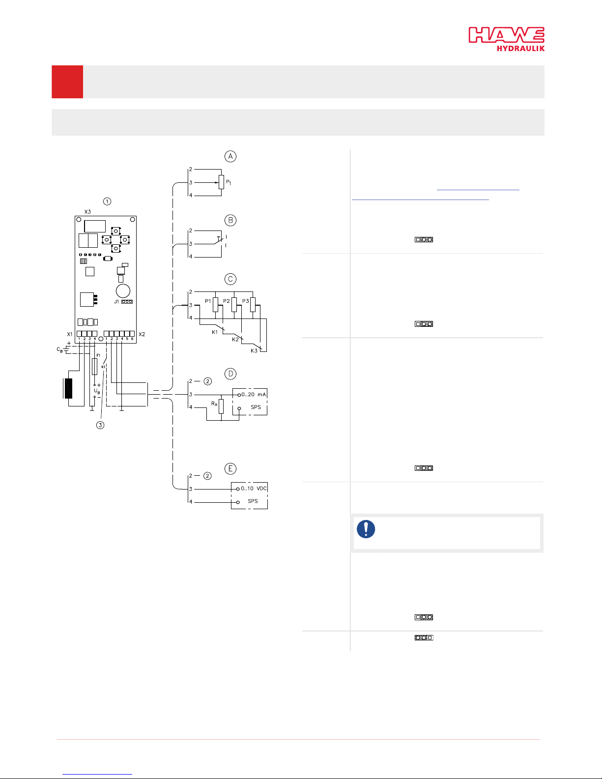
4Typical circuits
4.1 Actuation of hydraulic valves using a proportional solenoid
max.
min.
1Dither frequency
2Not used
3Enable/block
Example A Operation with external target value potentiometer
F1 = medium time-lag fuse; for nominal value see
"Setting instructions" in Chapter 3, "Installation,
operation and maintenance information"
CB = smoothing capacitor
P1 = target value potentiometer 10 kΩ, min. 0.1 W
Jumper J1 5 V DC
Example B Operation with target value changeover switch for both
congured target values Imin and Imax
F1 = as in example A
Jumper J1 5 V DC
Example C Operation with priority-dependent target value
changeover switch for four target values (relay circuit)
Functional example:
Rapid traverse mode 1 - K 1 → P1
Rapid traverse mode 2 - K 2 → P2
Creep mode - K3 → P3
Stop - K1 → K2 → K3 → ⊥
F1 = as in example A
Jumper J1 5 V DC
Example D Operation with external target value, power source from
PLC, CNC or PC
Note
Pay attention to the maximum load of the
power source.
F1 = as in example A
Rx = 250 Ω/0.5 W
Jumper J1 5 V DC
Example E Jumper J1 10 V DC

D 7831/D - EV1D - 09-2015-1.3
HAWE Hydraulik SE
Streitfeldstraße 25 | 81673 München | Postfach 80 08 04 | 81608 München | Germany
Tel +49 89 379100-1000 | Fax +49 89 379100-91000 | info@hawe.de | www.hawe.com
Further information
Additional versions
■Proportional amplifier type EV1M3: D 7831/2
■Proportional amplifier type EV22K2: D 7817/1
■CAN node type CAN-IO: D 7845 IO
■Programmable logic valve control with Probus type PLVC 21: D 7845-21
■Programmable logical valve control type PLVC 41: D 7845-41
■Programmable logic valve control type PLVC 8: D 7845 M
Application
■Proportional directional spool valve, type PSL and PSV size 2: D 7700-2
■Proportional directional spool valve, type PSL, PSM and PSV size 3: D 7700-3
■Proportional directional spool valve, type PSL, PSM and PSV size 5: D 7700-5
■Directional spool valve type NSWP 2: D 7451 N
■Clamping module type NSMD: D 7787
■Directional seated valve type EM and EMP: D 7490/1
Table of contents


