HAWE Hydraulik IEP 014-CP User manual

Battery pack type IEP
Assembly instructions
(Translation of the original instructions)
B 6130
02-2022-1.0en
Ident. No.: IEP 014-CP

© by HAWE Hydraulik SE.
The reproduction and distribution of this document as well as the use and communication of its contents to others without explicit
authorization is prohibited.
Offenders will be held liable for the payment of damages.
All rights reserved in the event of patent or utility model applications.
Brand names, product names and trademarks are not specifically indicated. In particular with regard to registered and protected names
and trademarks, usage is subject to legal provisions.
HAWE Hydraulik respects these legal provisions in all cases.
HAWE Hydraulik cannot provide individual guarantees that the stated circuits or procedures (including in part) are not subject to the
intellectual property rights of third parties.
Printing date / document generated on: 09.03.2022
2/39 B 6130 - 02-2022 - 1.0en HAWE Hydraulik SE

Table of Contents
1 About these instructions.................................................................................................................................. 4
1.1 Target audience................................................................................................................................................. 4
1.2 Safety instructions and symbols...........................................................................................................................4
1.3 Applicable documents.........................................................................................................................................6
2 For your safety................................................................................................................................................ 7
2.1 Intended use.....................................................................................................................................................7
2.2 Misuse.............................................................................................................................................................. 7
2.3 Residual risks.................................................................................................................................................... 7
2.4 Duties of the operator........................................................................................................................................8
2.5 Qualification of the personnel............................................................................................................................. 8
2.6 Personal protective equipment.............................................................................................................................9
3 About this product......................................................................................................................................... 10
3.1 Markings..........................................................................................................................................................10
3.2 Structure......................................................................................................................................................... 11
3.3 Functions........................................................................................................................................................ 12
3.4 Control............................................................................................................................................................14
3.5 Connector assignment....................................................................................................................................... 15
3.6 Number of cycles............................................................................................................................................. 15
4 Transport and storage..................................................................................................................................... 16
4.1 Transport equipment......................................................................................................................................... 16
4.2 Scope of delivery............................................................................................................................................. 16
4.3 Checking the delivery........................................................................................................................................17
4.4 Storage........................................................................................................................................................... 17
5 Assembly and installation...............................................................................................................................18
5.1 Electrical connection........................................................................................................................................ 18
6 Start-up......................................................................................................................................................... 20
6.1 Safety devices and performance limitations..........................................................................................................21
7 Operation....................................................................................................................................................... 23
8 Maintenance...................................................................................................................................................25
8.1 Maintenance plan............................................................................................................................................. 26
9 Disassembly and disposal................................................................................................................................27
10 Troubleshooting..............................................................................................................................................29
11 Appendix........................................................................................................................................................35
11.1 General data.................................................................................................................................................... 35
11.2 Weight............................................................................................................................................................ 35
11.3 Electrical data..................................................................................................................................................36
HAWE Hydraulik SE B 6130 - 02-2022 - 1.0en 3/39

1About these instructions
This manual is part of the product and describes the safe and proper use in all operating phases.
All photos and drawings in this manual show an available product variant. For precise details concerning
the variant you have purchased, please refer to the type plate attached to the product.
Read instructions before use.
Make the manual accessible to operating and maintenance personnel at all times.
Keep this manual for the lifetime of the product.
Only pass on the product to third parties together with this manual.
1.1 Target audience
The target audience of this manual is trained and qualied personnel who are familiar with the installa-
tion, operation and maintenance of machines.
The manual provides relevant information for the machine manufacturer and machine operator as well as
for training courses.
You can request further information on the product at: HAWE Hydraulik SE, Einsteinring 17, 85609
Aschheim/Munich, Germany.
1.2 Safety instructions and symbols
Safety indication In these instructions, the following warning and safety notes are used:
Symbol Meaning
DANGER
Draws your attention to a hazardous situation that can lead directly to
serious injury or death if not avoided.
WARNING
Draws your attention to a hazardous situation that can indirectly lead to
serious injury or death if not avoided.
CAUTION
Draws your attention to a hazardous situation that can indirectly lead to
light to moderate injury if not avoided.
Notice to prevent environmental and material damage.
Information to ensure the correct use of the product.
4/39 B 6130 - 02-2022 - 1.0en HAWE Hydraulik SE
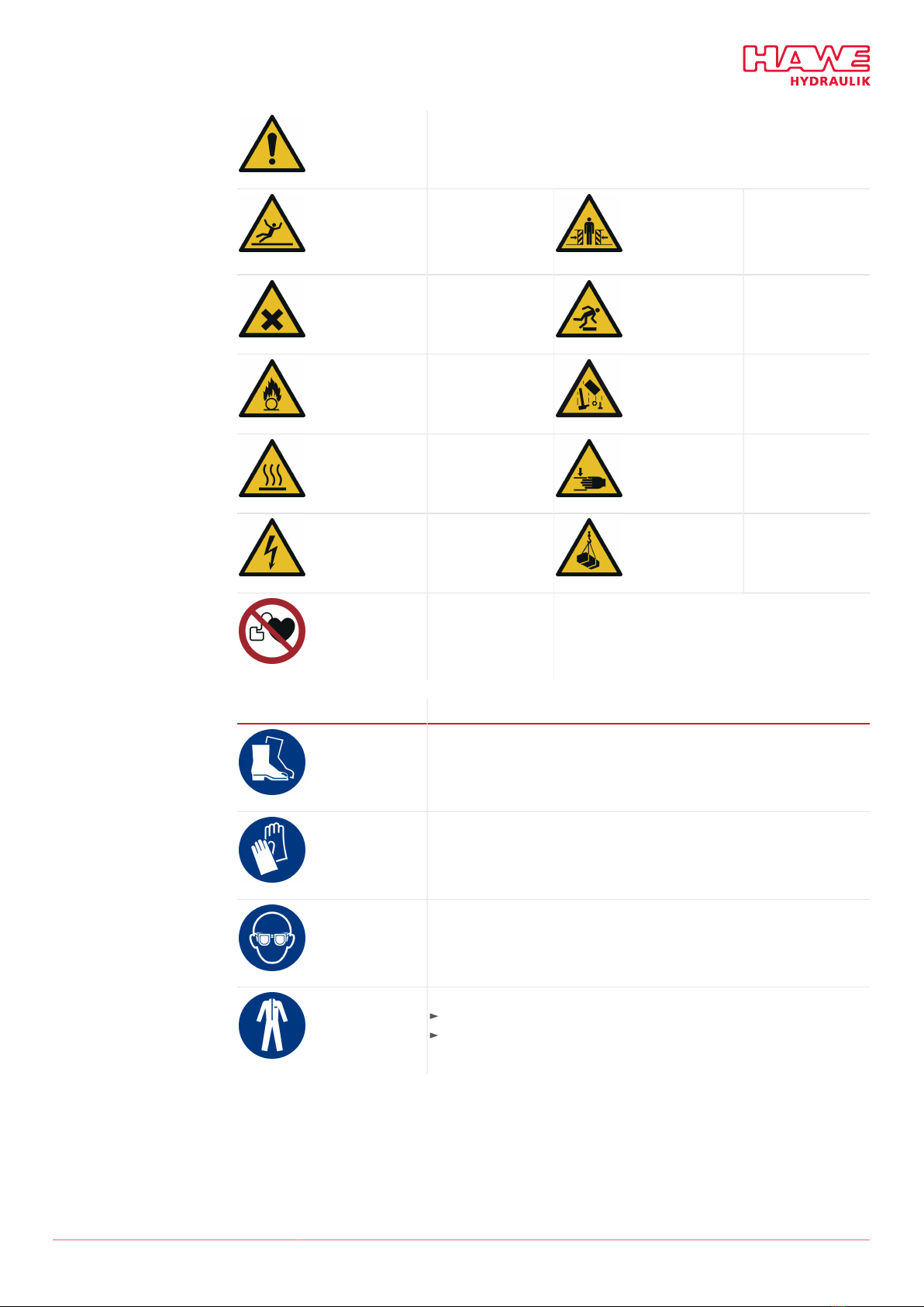
Safety symbols General safety symbol
Draws your attention to additional safety information.
Slipping hazard Dragging hazard from
moving parts
Harmful substances Tripping and falling
hazard
Fire accelerants Falling loads
Burn hazard Crushing hazard
Electrical voltage Suspended loads
No access to persons
with pacemakers and
defibrillators
Mandatory signs Protective equipment
Safety boots
Wear appropriate safety boots to protect your feet against mechanical
hazards
Work gloves
Wear suitable work gloves to protect your hands against chemical and
mechanical hazards.
Safety goggles
Wear safety goggles to protect your eyes against chemical and mechanical
hazards.
Protective clothing
Wear tted clothing without protruding parts.
Follow the safety data sheet of the hydraulic uid.
HAWE Hydraulik SE B 6130 - 02-2022 - 1.0en 5/39

1.3 Applicable documents
Standards Designation
2014/35/EU Low Voltage Directive
2014/30/EU EMC Directive
The protective objectives of DIRECTIVE 2014/30/EU are achieved by explicit
application of EN 60204-1, section 4.4.2 Electromagnetic Compatibility
(EMC).
Documents
D 6130 Data sheet battery pack type IEP
6/39 B 6130 - 02-2022 - 1.0en HAWE Hydraulik SE
2For your safety
The product is built according to the state of the art and recognized safety regulations.
Nevertheless, there is a risk of personal injury and damage to property if this chapter and the safety
instructions in this manual are not observed.
2.1 Intended use
■The product is a technical work tool and intended for commercial and industrial use only.
■The product may only be operated in accordance with the technical data, operating conditions and
performance limits specied in this manual.
■Only use original accessories and original spare parts approved by the manufacturer.
■Temperature range: Charging: 0 to 40°C
■Temperature range: Discharging: -10 to 45°C
■Suitable for operation up to 2000 m above sea level
■Use of the product in environments with intensive electrostatic elds and where strong electromag-
netic procedures are present, or in the immediate vicinity of parts and parts at high voltages must be
avoided.
■The product satises protection class IP65, exclusively when the main connector is connected or
engaged.
Electronic product
The product must not be commissioned by the machine manufacturer unless the higher-level
machine/system complies with the requirements of the applicable Machinery and EMC Directives.
2.2 Misuse
■Use in other operating modes than specied in the intended use
■Using the product beyond the specied performance limits
■Use of the product in potentially explosive atmospheres and in the presence of highly ammable
substances/media is prohibited.
2.3 Residual risks
WARNING
Danger of death due to explosion or re in the system or the device.
If a lithium-ion battery catches re, the re can spread in an explosive manner, with highly hazardous
potential. This can lead to fumes hazardous to health, to severe injuries or death.
Move away from the device or the re.
Call the re brigade and tell them the incident concerns a lithium-ion battery.
Provide re extinguishers with a high cooling effect.
HAWE Hydraulik SE B 6130 - 02-2022 - 1.0en 7/39

WARNING
Electrical and magnetic elds
Consumers connected to the battery can generate electrical and magnetic elds. These elds affect the
operation of heart pacemakers and implanted defibrillators.
Wearers of heart pacemakers and implanted defibrillators must maintain a sufcient distance from
magnets.
Wearers of such devices must be warned against approaching too closely to magnets.
Block off the area around the drive system, and provide suitable warning signs on the barriers.
CAUTION
Health hazard due to contact with vapours from damaged batteries.
Poisonous vapours can be released if the battery pack (battery) is damaged. Contact with skin, eyes and
mucous membranes can lead to irritation.
Wear personal protective equipment (safety glasses, gloves, mouth protection).
In the event of contact, thoroughly wash the affected body parts with water.
Call a doctor.
2.4 Duties of the operator
Observe and comply with regulations:
The product must not be commissioned until the complete higher-level machine or system complies
with the provisions, safety regulations and standards relevant in that country for the application.
Observe and apply regulations for accident prevention and environmental protection.
Assess and document the new dangers in the complete system’s manual.
Operate product safely:
Despite safety devices, the product still poses residual risks. Observe the safety instructions in this
manual to reduce health hazards and avoid dangerous situations.
The operating company must ensure the operating conditions (see the technical data) are within the
limits for use of the product.
Keep all instructions / signs on the product in legible condition and observe them.
Instruct personnel:
Regularly train the personnel in all points of these instructions and ensure that they are observed.
Ensure the terms of the industrial safety and operating instructions are observed.
Only use qualied personnel. Due to their training and experience, the qualied personnel must be
able to recognize risks and avoid possible hazards.
2.5 Qualification of the personnel
The activities described in this manual require comprehensive knowledge of the mechanical and electrical
aspects.
For transport and handling of heavy loads, additional knowledge of lifting gear and slings is necessary.
The activities may be performed only by an appropriately qualied person or by a person under
instruction under the supervision of a qualied person.
Other activities described in this manual may be performed only by HAWE or by authorised specialist
companies.
The personnel must have read and understood this manual.
8/39 B 6130 - 02-2022 - 1.0en HAWE Hydraulik SE

Trained personnel Personnel instructed comprehensively, by skilled staff on behalf of the owner, in how to perform its
appointed tasks and in how to use the product safely.
Specialist personnel Due to their technical training, knowledge and experience, specialists are able to assess and carry out the
assigned work and can independently recognize possible dangers.
Qualied electrician A person with appropriate professional training, knowledge and experience, so that he/she can recognize
and avoid dangers that can be caused by electricity.
Auditor Persons of a technical inspection body who are authorized to perform testing and monitoring tasks for
pressure equipment and electrical systems.
2.6 Personal protective equipment
Personal protective equipment is designed to prevent and reduce hazards.
In the instructions, safety instructions with mandatory symbols indicate the wearing of special
protective equipment for special activities.
Instruction and supply is carried out by the operator.
HAWE Hydraulik SE B 6130 - 02-2022 - 1.0en 9/39
3About this product
3.1 Markings
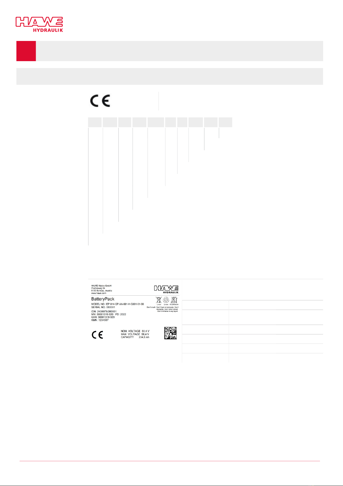
Device labelling CE mark
The CE mark can be found on the type plate
Order coding IEP 014 -CP -AA -001 -H -C 001 -01 -00
Mechanical auxiliary functions
Electrical auxiliary functions
BMS parameter set
BMS type
Heat management
Housing type including plug
Cell type
Cell configuration
Cells in series (nominal voltage)
Basic type
Order coding IEP
The order coding can be found on the type plate
Type plate
The type plate with the manufacturer’s contact data carries the
following data on the handle side:
Model No Order coding
Serial No Serial No (also stamped on to the top face
of the front cover)
IDN Identification number
MN Material number
KAN Customer order number
KMN Customer material number
10/39 B 6130 - 02-2022 - 1.0en HAWE Hydraulik SE
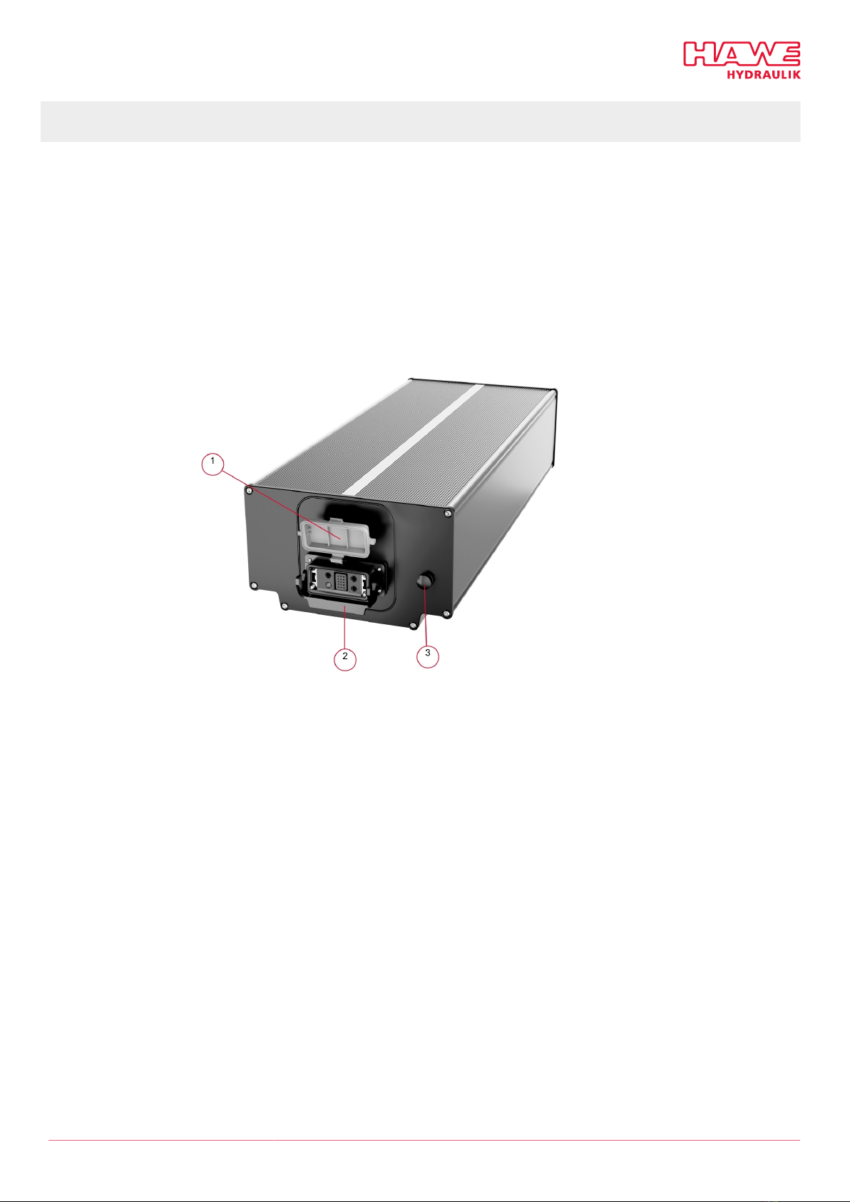
3.2 Structure
The energy pack type IEP consists of linked-up lithium ion cells. The integrated battery management
system (BMS) continuously monitors the battery’s condition. This protects the battery from excessive
charge and deep discharge, excessive or insufficient temperature and excessive current. It performs
balancing and optimises the battery’s service life.
The product is available in the following versions:
■IEP 014-CP
The product satises protection class IP65, exclusively when the main connector is connected or
engaged.
1Cover of the main connector
2Locking clip
3Pressure equalisation membrane
HAWE Hydraulik SE B 6130 - 02-2022 - 1.0en 11/39

Assemblies of the IEP This block diagram shows the principal assemblies of the battery pack.
1Integral pre-charge
2Relay monitoring
3Current monitoring
4Temperature monitoring
5Integral heater
6Cell balancing
7SOC calculation
8CAN interface
9Short circuit protection (fuse)
10 Lithium-ion cells
11 Inputs
12 Main connector
3.3 Functions
Integrated precharge Precharge: The BAT+ relay is bridged with a 2Ω resistance. This produces current ow charging the
capacitors in the connected consumers, e.g. an inverter. When current ow undershoots the preset
maximum at the end of the precharge phase, the BAT+ relay closes and precharging ends.
Default parameters
■Precharge time: 0.65 s
■Current at end of precharge time: < 2 A
These parameters may be changed without notice during series production or be changed to match
customer requirements.
DAMAGE
■The lower the current at the end of the precharge time, the lower also the wear on the relay contacts.
■No more than 10 precharge operations may be performed or attempted within 10 minutes.
Two factors affect residual current at the end of the precharge time:
1. The connected capacity value. Experience has shown that the precharge facility’s design can handle
the reasonably expectable capacities.
2. Continuous current IDC at the end of the precharge time.
12/39 B 6130 - 02-2022 - 1.0en HAWE Hydraulik SE

Typical causes for IDC
■Consumers that are already attempting to supply power during precharging, e.g. DC/DC converters. In
this case, DS/DC converter power-up needs to be delayed so that it does not supply power until after
precharging has nished (e.g. via ‘enable pin’).
■Consumers with significant input capacities feature bleeder resistors (discharge resistors) that ensure
input capacities are discharged when switched off. Their resistances are typically within the low kΩ
range. Parallel circuits with multiple consumers will often result in significantly higher IDC.
Voltage monitoring The integral Battery Management System (BMS) monitors the voltage of the battery pack. If this
detects hazardous over-voltage or under-voltage it switches the pack off and outputs a corresponding
error report. It also switches the pack off if pre-dened or customer-specied charging or discharging
conditions are detected. This is part of normal operation and no error report is output. To avoid undue
wear of the relay contacts, the user must however congure his control system so that switching off
under load does not occur in the regular course of events.
Relay monitoring The status of the HV switch-off (relay) is monitored. This enables detection of any statuses incorrectly
closed (such as relay contacts welded) and statuses incorrectly open (such as a cable break in the relay
supply cable, lack of a vehicle-side safety bridge).
Current monitoring The integral current sensor (Hall sensor) measures the charging currents and discharging currents within
the system. The values are evaluated in the Battery Management System (BMS).
Temperature monitoring There are a total of 4 temperature sensors (NTC 10K) within the housing of the battery pack, these
are distributed uniformly within the installation area. The sensors are evaluated by the BMS. If the
temperatures measured lie outside the permitted limit values, the BMS triggers the opening of the main
contactor, thereby preventing the ow of current into the battery or from it.
Integral heater The battery incorporates an electric heater. When the battery pack is at a low temperature (below 5°C)
this serves to bring the temperature up to a level at which the data sheet species that the cells can be
charged or discharged.
The heater is active in the following modes:
■Drive
■Charge
■Heater request via CAN
As soon as the battery is active (ignition/CAN) the heater is automatically activated by the BMS.
As soon as the lowest temperature that is measured is found to be below 7°C, the heater is switched on.
It remains on until the lowest temperature that is measured reaches 9°C. The heater is also deactivated
if the difference between temperature readings received from the sensors is greater than 9°C.
The heating request via the CAN bus takes no account of the switch-off temperature, so it is the user
who must comply with the above limits. A switch-off is also performed at high differences in tempera-
ture or excess temperature of the overall battery pack. In addition there is a passive switch-off system
fully independent of the electronics. This is triggered if the heater is switched on at a temperature that
is too high. This system is self-resetting, but after its initial activation it changes its characteristics and
becomes "too sensitive".
To restore normal functionality of the heater, there is no other option than servicing the battery pack.
The use of the associated chargers in an under-temperature situation merely compensates the current
consumption of the heater. This allows the battery pack to be "pre-heated” until normal charging can be
performed.
Cell balancing The Battery Management System (BMS) performs passive cell balancing.
SOC calculation The Battery Management System (BMS) has an integral SOC calculation. This allows the charge status of
the battery to be read via the CAN bus.
HAWE Hydraulik SE B 6130 - 02-2022 - 1.0en 13/39

CAN interface Communication with the BMS is performed via the CAN bus. All the relevant data can be viewed. For
this see the CAN matrix which is provided in a separate document. Where a battery pack is connected in
parallel, we recommend a combination of terminal 15 and the CAN wake-up. This ensures that the CAN
and the BMS can communicate with each other and operate without problems.
3.4 Control
Central control system and
software
The control system for the superordinate machine is handled by the machine manufacturer. The machine
manufacturer must determine the operating modes for safe operation.
All required safety barriers, safety functions and safety controls must be put in place by the
superordinate machine’s manufacturer.
It remains the duty of the superordinate machine’s manufacturer to ensure that the product is
properly used in and approved for the overall system, the customer's environment and the target
market.
Make sure that the superordinate system/machine can perform the following functions and supplement
them in accordance with your own risk assessment:
■The technical data specifications in the data sheets must be complied with.
■Load circuit faults cannot trigger any hazard and can be safely rectied.
■Load circuit power supply failure will not result in danger.
■The battery does not feature integrated insulation monitoring (IMD). Should such be required for
safety engineering reasons or legally, insulation monitoring will need to be implemented in the
superordinate system.
■Observe the technical requirements relating to the IP class, environmental conditions and impact on
EMC:
°It must be possible to galvanically isolate the superordinate machine from the mains by means of a
main switch in order to enable work on live parts.
°Install the device in a well-ventilated room that is not too small, to protect it from overheating.
°Protect the device from moisture and dripping and splashing water.
■It is impossible for people to reach into the electrical circuit’s danger zone.
14/39 B 6130 - 02-2022 - 1.0en HAWE Hydraulik SE

3.5 Connector assignment
Connector assignment, voltage range of the start signal and electrical performance data are
detailed in the appendix under "Electrical data", page 36.
1Power module minus
2Signal module
3Power module plus
3.6 Number of cycles
The number of cycles (cycle life performance) is strongly dependent on the loading of the battery
and the conditions (temperature, charging currents and discharge currents) under which it is used. A
partial discharge of the battery reduces the loading and extends its service life, as does a partial charge.
Elevated temperatures and high currents have a negative effect on the cycle life performance.
■IEP 014-CP: Set to 3.98V per cell. This guarantees a higher number of cycles. If desired the charge
cut-off voltage can be raised to 4.20V, which creates a penalty against the achievable number of
cycles.
The following values serve as indications. No more exact conclusion can be reached until the
relevant proles of load, charge and temperature prole can be tested at the battery for the
application in question.
Charge status (V/cell) Discharge cycles available stored energy in %
4,20 300 - 500 100
4,15 400 - 700 90 -95
4,10 600 - 1000 85 -90
4,05 850 - 1500 80 -85
4,00 1200 – 2000 70 -75
3,90 2400 – 4000 60 -65
HAWE Hydraulik SE B 6130 - 02-2022 - 1.0en 15/39
4Transport and storage
Observe the following safety instructions additionally to the safety instructions in chapter For your
safety.
CAUTION
Personal injury through tipping or falling load
The product might tip over or fall during transport. This could lead to hands and feet becoming trapped.
Adhere to the symbols on the packaging.
Use permitted transport aids to carefully transport the product as close to the installation location
as possible.
Select transport aids that will allow the maximum load to be transported safely.
Wear safety shoes, work gloves and safety glasses.
4.1 Transport equipment
DAMAGE
Danger for electronic components – electrostatic discharge – material damage
Deliver product in ESD protective packaging.
DAMAGE
Material damage due to mechanical damage
Protect the product against mechanical damage, e.g. by applying suitable padding.
such as foam, covers, cardboard
Only tested and approved aids are permitted for use.
4.2 Scope of delivery
The supply of the completely installed unit corresponds to the order coding listed on the order:
■Battery pack as ordered
■User manual
Optional
■3 kW charger (1-phase / 230 VAC)
■5 kW charger (3-phase / 400 VAC)
■Cables with mating connectors (tailor-made solutions)
■Energy cage (battery housing)
Not included in the scope
of delivery
■Accessories for commissioning
16/39 B 6130 - 02-2022 - 1.0en HAWE Hydraulik SE

4.3 Checking the delivery
Unpacking 1. Take out the product.
2. Check that the product is complete and check for transport damage.
Note any transport damage on the transport documents or on the carrier's delivery note.
Take photos of any transport damage and show them to the manufacturer.
3. Dispose of the product packaging correctly in accordance with local regulations.
DAMAGE
Claim immediately for all defects at:
HAWE Mattro GmbH
Pocherweg 24
6130 Schwaz
Tel.: +43 5242 20904-0
Claims for damage can be accepted only if submitted within the applicable claim periods. HAWE cannot
accept liability for later claims.
4.4 Storage
DAMAGE
Property damage from incorrect storage
Incorrect storage can lead to damage. Refer to the technical data.
Store the product and its individual components as follows:
■Do not store outdoors.
■Store in an area that is dry and free of dust.
■Protect against sunlight (UV radiation). (dark)
■Storage temperature 0 to 20°C.
■Humidity (atmospheric humidity 50% or less)
■Protected against splashed water and dripping water.
■Do not store near sources of ignition or heat, aggressive media (e.g. acids, fuels or lubricants) or
ozone-producing sources of light (e.g. fluorescent light sources, mercury-vapour lamps).
■Do not place in the immediate vicinity of sources of heat (such as radiators)
■Place only in areas equipped with re alarms.
■Maintain the required safety clearance from ammable materials (at least 2.5m).
■Ensure the storage area is acceptable to the re brigade ofcer and the insurance company.
■Mark the storage area with appropriate notices.
■Prevent excessive cell voltage (during storage, the SOC of the battery must lie between 35 and 55%.)
■Avoid deep discharge. (Check the voltage and SOC of the battery 1x per month, more often if subject
to rapid discharging.)
HAWE Hydraulik SE B 6130 - 02-2022 - 1.0en 17/39
5Assembly and installation
Observe the following safety instructions additionally to the safety instructions in chapter For your
safety.
DAMAGE
Material damage due to mechanical damage
Protect the product from mechanical damage during assembly and installation, e.g. by padding.
5.1 Electrical connection
DANGER
Risk of fatal injury from electric shock
Touching live components directly or indirectly causes injury or death.
Electrical and electronic components must only be replaced and connected by trained specialist
personnel.
Obey all applicable electrical safety rules.
Only connect electric lines to the hydraulic system while the system is de-energized.
DANGER
Risk of injury due to electric shock from the operating capacitor
Burns, serious injuries or death may result if electromagnetic waves lead to functional interference with
the temperature measurement.
Ensure the operating capacitor is discharged to a safe voltage level.
WARNING
Electrical and magnetic elds
Electrical and magnetic elds impair the functionality of cardiac pacemakers and implanted defibrilla-
tors.
People with pacemakers or implanted defibrillators must maintain a sufcient distance from
magnets.
Advise people with pacemakers or implanted defibrillators against approaching magnets.
Cordon off the area around the drive system and afx suitable warning signs to the barriers.
18/39 B 6130 - 02-2022 - 1.0en HAWE Hydraulik SE

DAMAGE
Hazard for electronic components – property damage
Electromagnetic waves lead to malfunctions of electrical or electronic equipment.
To prevent electrostatic discharge, do not touch electronic components and contacts.
After switching off the electrical power supply, wait at least 15 minutes for the energy stored in the
capacitors to dissipate.
Do not expose components to moisture and an aggressive environment.
To avoid overheating, always keep ventilation openings (if any) open and allow sufcient air
circulation.
This is to avoid electromagnetic waves leading to functional interference
Twist and shield the conductors.
Route intersections at right angles.
Connect the shield at only one end and close to the control system at ground potential.
Route control cables and power cables separately.
Leave a 10 to 20 cm gap between the control cables and power cables.
Provide separate shields for analogue and digital control lines.
Tool ■Voltage tester to EN 61243-3 of at least measurement category CAT III 600V to the standard ICE
61010-1.
■Always use suitable cables. Refer to DIN VDE 0276-1000 or the equivalent national regulations to
determine the current-carrying capacity of the power cables.
Electrical connection 1. Secure the unit against being switched on unintentionally.
2. Ensure that nobody is in the danger area.
3. Place the product in the higher-level machine, and secure it.
✓Make sure that when the battery pack is installed, the main connection of the battery pack does
not face upwards.
When replacing the battery
pack
1. Secure the unit against being switched on unintentionally.
2. Ensure that nobody is in the danger area.
3. Disconnect the main connection at the product.
4. Make the connection of the new battery pack as described in Electrical connection .
HAWE Hydraulik SE B 6130 - 02-2022 - 1.0en 19/39

6Start-up
Observe the following safety instructions additionally to the safety instructions in chapter For your
safety.
CAUTION
Risk of re due to short circuit currents.
Touching live components, directly or indirectly, will cause injuries or death.
Electrical and electronic components must only be replaced and connected by trained specialist
personnel.
Comply with the relevant electrical safety regulations.
DAMAGE
Damage to equipment due to the EMC interference
Electromagnetic waves lead to malfunctions of electrical or electronic equipment.
To prevent this:
Twist and shield the conductors.
Route intersections at right angles.
Connect the shield at only one end and close to the control system at ground potential.
Route control cables and power cables separately.
Leave a 10 to 20 cm gap between the control cables and power cables.
Provide separate shields for analogue and digital control lines.
Only trained specialist personnel may perform commissioning.
The unit is secured against being switched on unintentionally.
1. Check the battery pack has been connected correctly:
✓Mechanical: Attachment to the higher-level machine, the frame and the base
✓Electrical: Wiring, power supply, control
✓Penetration of liquids into the device (for instance during installation work) must be prevent-
ed. (Penetration of liquids will lead to leakage currents or even outright short circuits, leading to
damage or destruction (by re) of the device.)
✓Cables must be sealed.
2. Set up the CAN interface. (page 21). Check
3. "Safety devices and performance limitations", page 21 .
20/39 B 6130 - 02-2022 - 1.0en HAWE Hydraulik SE
Table of contents
Popular Batteries Pack manuals by other brands


BYD
BYD Battery-Box C130 installation manual

Klein Tools
Klein Tools KTB5 instruction manual

BYD
BYD Battery-Box Premium LVL 15.4 Service guidelines

Victron energy
Victron energy Lynx Ion BMS 400A manual

Kon-TEC
Kon-TEC KT-LFP1250 Operation and maintenance manual

C&D Technologies
C&D Technologies UPS12-100MR Maintenanse Instructions