HAWE Hydraulik DG 1 R User manual

Pressure switch type DG
Product documentation
D 5440
10-2020-1.1
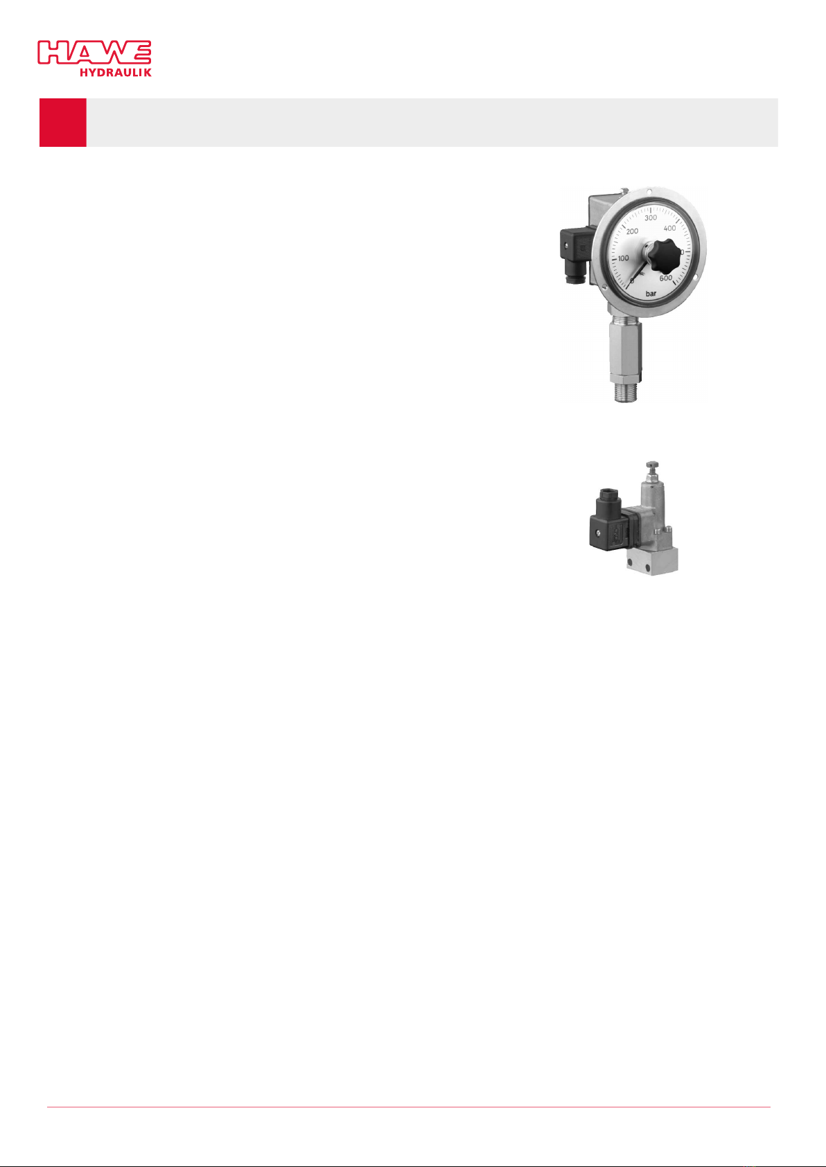
Piston-type pressure switch
Operating pressure pmax: 00 bar
Pressure switch type DG
Product documentation
D 5440
10-2020-1.1
Piston-type pressure switch
Operating pressure pmax: 00 bar

© by HAWE Hydraulik SE.
The reproduction and distribution of this document as well as the use and communication of its contents to others without explicit
authorisation is prohibited.
Offenders will be held liable for the payment of damages.
All rights reserved in the event of patent or utility model applications.
Brand names, product names and trademarks are not specifically indicated. In particular with regard to registered and protected names
and trademarks, usage is subject to legal provisions.
HAWE Hydraulik respects these legal provisions in all cases.
Printing date / document generated on: 04.11.2020
2/21 D 5440 - 10-2020-1.1 © HAWE Hydraulik SE

Contents
1 Overview of pressure switch type DG...................................................................................................................4
2 Available versions, main ata............................................................................................................................. 5
3 Parameters......................................................................................................................................................... 8
3.1 General and hydraulic........................................................................................................................................... 8
3.2 Electrical data....................................................................................................................................................10
4 Dimensions...................................................................................................................................................... 12
5 Assembly, operation an maintenance recommen ations.....................................................................................17
5.1 Intended use..................................................................................................................................................... 1
5.2 Assembly information......................................................................................................................................... 1
5.2.1 Preparing the base plate for DG 3........................................................................................................................ 1
5.3 Operating instructions.........................................................................................................................................18
5.4 Maintenance information..................................................................................................................................... 18
5.5 Adjustability and switching pressure.....................................................................................................................19
6 Other information.............................................................................................................................................20
6.1 Accessories, spare parts and separate components.................................................................................................. 20
© HAWE Hydraulik SE D 5440 - 10-2020-1.1 3/21
1Overview of pressure switch type DG
Pressure switches open and close an electrical contact at a previously dened
pressure. As soon as the pressure is reached, a further work step is started or
stopped by an electrical signal.
Features an benets:
■Compact design
■Option of integration into the HAWE modular system
■Operating pressures up to 1000 bar
Inten e applications:
■General hydraulic systems
■Machine tools
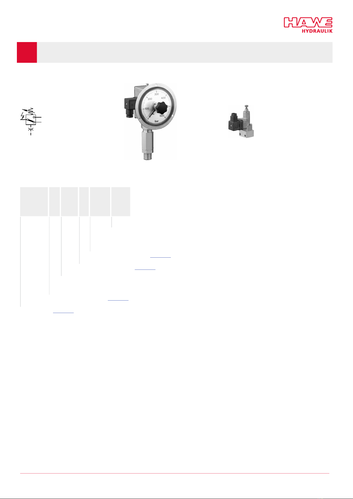
Pressure switch type DG 1
Pressure switch type DG 3
4/21 D 5440 - 10-2020-1.1 © HAWE Hydraulik SE
2Available versions, main ata
Circuit symbol: DG 1 DG 3
Or er co ing example:
DG 1 RF
DG 33
DG 35
DG 34 M
- KB
V
- YS 8
300 F
Pressure setting (factory-set, optional), bar ■Series: setting with increasing pressure
■Coding F: setting with decreasing pressure
Hy raulic connection "Table 4"
A justment evices "Table 3"
Low-temperature seal congurable only with DG 35 -X. and DG 364 -X.
Their micro switches are installed with gold contacts.
Electrical connection "Table 2"
Basic type "Table 1"
© HAWE Hydraulik SE D 5440 - 10-2020-1.1 5/21
Table 1 Basic type
Pressure setting (range) (bar)Basic type Description
pmin–max pmax
DG 1 R Scale, pipe connection
DG 1 RF Scale, front ring for control panel installation, pipe connection
DG 1 RU
DG 1 RUFS Scale mounted with 180° rotation, for “suspended” installation
20 ... 600 600
DG 33
DG 34
DG 35 *
DG 36
DG 364 *
DG 365
Manifold mounting 200 to 00
100 ... 400
20 to 250
4 to 12
4 to 50
12 to 1 0
00
*DG 35 and DG 364 in version -X.-KB have different hydraulic data depending on the temperature.
For further information, please look at Chapter 3.1, "General and hydraulic".
Table 2 Electrical connection
Co ing Electrical connection Protection class
(IEC 60529)
DG 1 R
DG 1 RF
DG 1 RU
DG 1 RS
DG 1 RFS
DG 1 RUFS
DG 3
-- Terminal connection IP 54 o
-- Line connector
DIN EN 1 5 301-803 A
IP 65 o o
- X DIN EN 1 5 301-803 A
(without line connector)
IP 54 o
- X1 DIN EN 1 5 301-803 A
(without line connector)
IP 54 o
- AMP AMP Junior Timer IP 6 o
- S SCHLEMMER (bayonet PA 6) IP 6 o
- M M12x1 (in compliance with DESINA) IP 6 o
Table 3 A justment evices
Co ing Version
No esignation - Turn knob for DG 1 R(S), DG 1 RF(S)
- Adjusting screw for DG 3..
- DG 35.. - KB and DG 364..- KB with gold contacts only have an adjusting screw
Ronly DG 3.. : Adjustable by hand (wing bolt and wing nut)
Vonly DG 3.. : Turn knob
Honly DG 3.. : - Lockable turn knob (BKS lock)
- Key in line with factory specifications for the automotive industry; a key is included in the scope
of delivery (with an additional key held by authorised plant personnel).
6/21 D 5440 - 10-2020-1.1 © HAWE Hydraulik SE

Table 4 Hy raulic connection
Suitable for DG 1 R..
For combination with various ttings, see D 065
Co ing Connection type
Directly using a type-B pipe screw connection in accordance with DIN 3852-2
G 1/4 or G 1/2 A connection thread (ISO 228-1 (BSPP))
No esignation
With union nut DIN 16283 (pressure gauge screw tting, e.g. DIN 162 0)
Suitable for DG 3..
Co ing Connection type
No esignation Manifold mounting
- 1/4 Pipe connection G 1/4 (BSPP)
- Y1 Tapped journal G 1/4 A (BSPP)
- Y2 Tapped journal M12x1.5
- Y3 Tapped journal G 1/8 (BSPP)
- YS 6
- YS 8
Tapered cone #6 and #8 for a cutting ring and union nut
- Y6
- Y8
Pipe bracket #6 and #8 for a pipe screw connection
© HAWE Hydraulik SE D 5440 - 10-2020-1.1 /21
3Parameters
3.1 General an hy raulic
Description Pressure switch
Design Spring-loaded piston-type pressure switch
Mo el Pipe connection, manifold mounting
Material DG 1: Galvanised steel housing
DG 3: Zinc die casting housing
Tightening torques See Chapter 4, "Dimensions"
Installation position DG 1 R.. = Vertical, sideways scale, hydraulic part at the bottom
DG 3.. = As desired
Hy raulic ui Hydraulic oil: according to part 1 to 3;
ISO VG 10 to 68 according to DIN ISO 3448
Viscosity limits: min. approx. 4, max. approx. 1500 mm2/s
opt. operation approx. 10... 500 mm2/s.
Also suitable for biologically degradable hydraulic uids type HEPG (polyalkylene glycol)
and HEES (synthetic ester) at operating temperatures up to approx. + 0°C.
Cleanliness level ISO 4406
21/18/15...19/1 /13
Temperatures Ambient: approx. -40 ... +80°C, Fluid: -25 ... +80°C, Note the viscosity range!
Start temperature: down to -40°C is permissible (observe start viscosities!),
as long as the steady-state temperature is at least 20K higher during subsequent operation.
Biologically degradable pressure uids: Observe manufacturer's specifications. By considera-
tion of the compatibility with seal material not over + 0°C.
Hy raulic ata of DG 35 -X.-KB an
DG 364 -X.-KB Temperature range -30°C < x < 0°C 0°C < x < 50°C
Speed of pressure change < 6 bar/s
DG 35 80 ... 250 bar 20 ... 250 barPressure setting pmin to pmax
DG 364 35 ... 50 bar 12 ... 50 bar
DG 35Maximum pressure pmax
DG 364 500 bar 500 bar
8/21 D 5440 - 10-2020-1.1 © HAWE Hydraulik SE

Weight
Type
DG 1 R.. = 1.3 kg
DG 33 = 0.3 kg
DG 34 = 0.3 kg
DG 35 = 0.3 kg
DG 36 = 0.3 kg
DG 364 = 0.3 kg
DG 365 = 0.3 kg
DG 3.. - 1/4 = 0.4 kg
DG 3.. - Y.. = 0.4 kg
© HAWE Hydraulik SE D 5440 - 10-2020-1.1 9/21

3.2 Electrical ata
Switching operations/h Reference values approx. 2000 switching operations/h max. (roughly equally distributed).
Note the number of possible switching cycles; see below. Switching accuracy * 2 to 3%
(repeat accuracy for increasing pressure!)
DG 1 R
DG 1 RF
DG 1 RU
DG 1 RS
DG 1 RFS
DG 1 RUFS
DG 3. - X
DG 3. -S
DIN EN 1 5 301-803 ATerminal connection
Cable 3x0. 5
See also the product assembly
instructions
3-pole 3-pole
Electrical connection
DG 3. - AMP DG 3. - M DG 3. - X1
AMP Junior Timer DIN EN 1 5 301-803 A
4-pole 4-pole 3-pole
1+24 V
2PNP switching signal
3GND
4IO-Link
10/21 D 5440 - 10-2020-1.1 © HAWE Hydraulik SE
Pressure switch DG 1.. DG 3..
Micro switch type X 04-Z 25 XCG 3
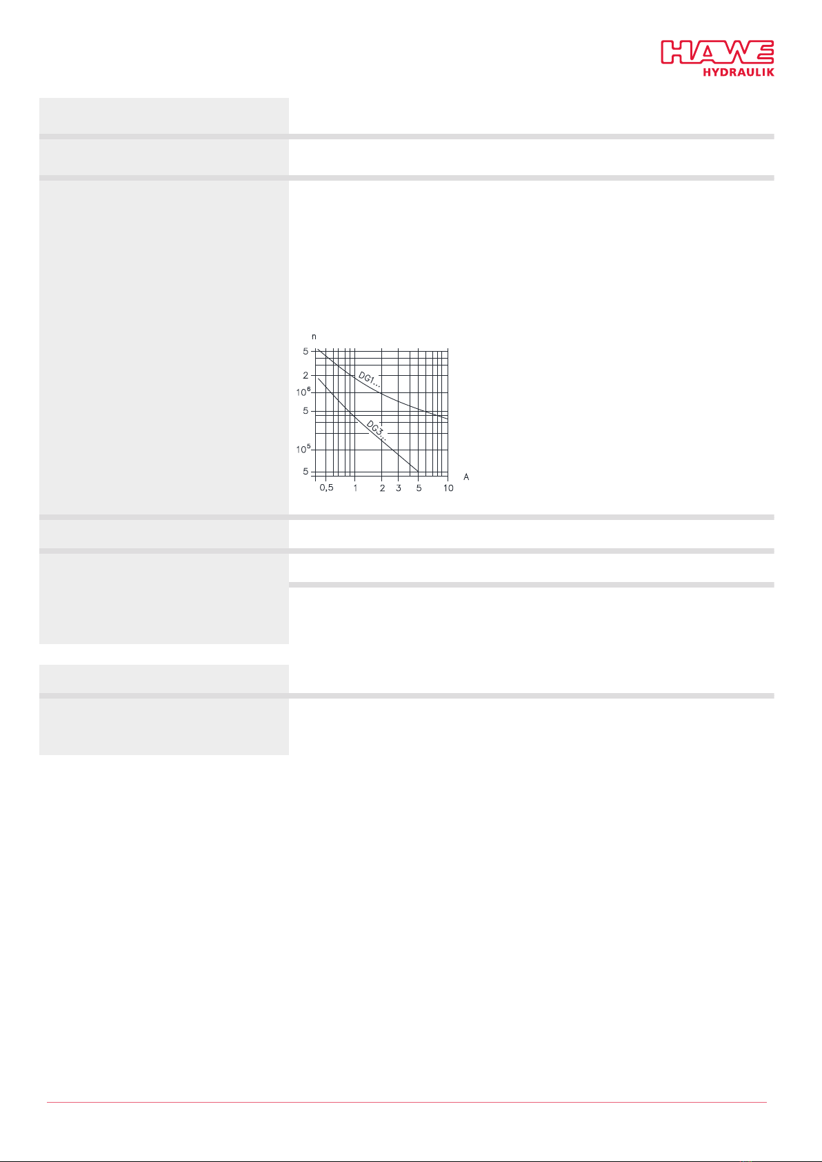
Mechanical lifetime approx./switching cycles 10 x 10610 x 106
For 12 V DC = 4 A and L/R = 10 ms
1 x 1060.35 x 106
For 230 V, 1 A and cos. 9 = 0.3
A current at 230 V AC; n switching cycles
Maximum supply voltage Umax < 50 V AC or 5 V DC
2 ASwitching current Imin
To ensure a safe contact, the current must not fall below certain minimum values:
24 V DC = Imin = 10 mA
12 V DC = Imin = 100 mA
Version DG 3. -X. -KB
Switching current Imin To ensure a safe contact, the current must not fall below certain minimum values:
24 V DC = Imin = 5 mA
12 V DC = Imin = 100 mA
© HAWE Hydraulik SE D 5440 - 10-2020-1.1 11/21

4Dimensions
All dimensions in mm, subject to change.
DG 1 R
1Cable fitting PG 9
2Ground connection
3Actuation cylinder
4Scale housing
5Setting knob for main switch
NOTE
For types DG 1.., the scale housing > must not be twisted relative to the hex (width across ats 2 ) = for functional-technical
reasons!
DG 1 RS
1Line connector can be mounted offset by 4x90°
DG 1 RU
12/21 D 5440 - 10-2020-1.1 © HAWE Hydraulik SE

DG 1 RF
With front ring for switch panel installation
1Cable fitting PG 9
2Ground connection
3Actuation cylinder
4Scale housing
5Setting knob for main switch
6Fixing holes are rotated by 180° in version “U”.
NOTE
For types DG 1.., the scale housing > must not be twisted relative to the hex (width across ats 2 ) = for functional-technical
reasons!
DG 1 RFS (DG 1 RUFS)
1Line connector can be mounted offset by 4x90°
© HAWE Hydraulik SE D 5440 - 10-2020-1.1 13/21

Hy raulic connection
G 1/4 (BSPP) thread
for pipe screw connection
G 1/2 (BSPP) thread
e.g. pressure gauge screw tting
G 1/2 (BSPP) thread
Fitting type X1 (example) from D 065
DG.. can be tted in any direction
1Cu sealing ring DIN 7603
Base plate hole pattern
1Hydraulic connection
DG 3..
Series (adjustment device without designation)
1Plug can be mounted offset by 4x90°
2Sealing option
3Sealing with O-ring
DG 3..X DG 3..M
1Light ring (yellow)
14/21 D 5440 - 10-2020-1.1 © HAWE Hydraulik SE
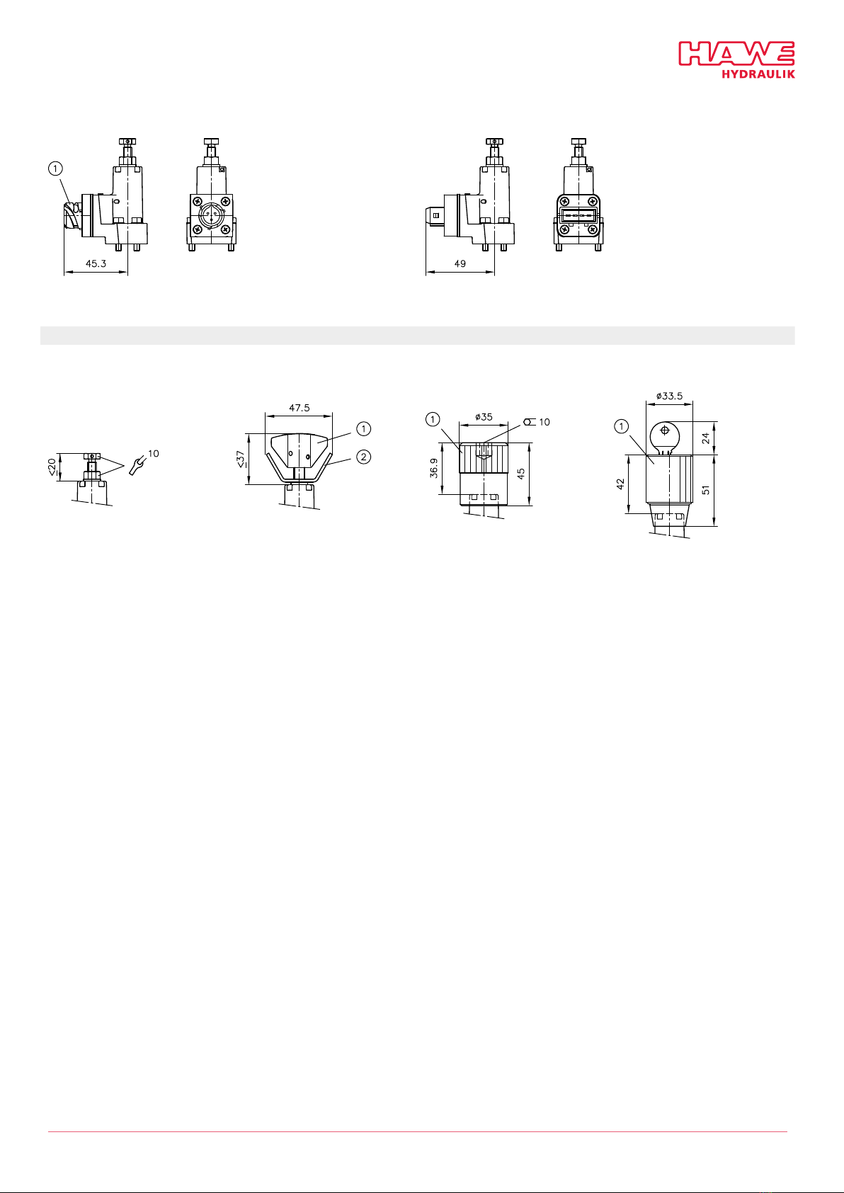
DG 3..S
1Bayonet PA 6 (Schlemmer)
DG 3..AMP
A justment
No designation Coding RCoding VCoding H
1Wing bolt
2Wing nut 1Turn knob
1Turn knob
© HAWE Hydraulik SE D 5440 - 10-2020-1.1 15/21
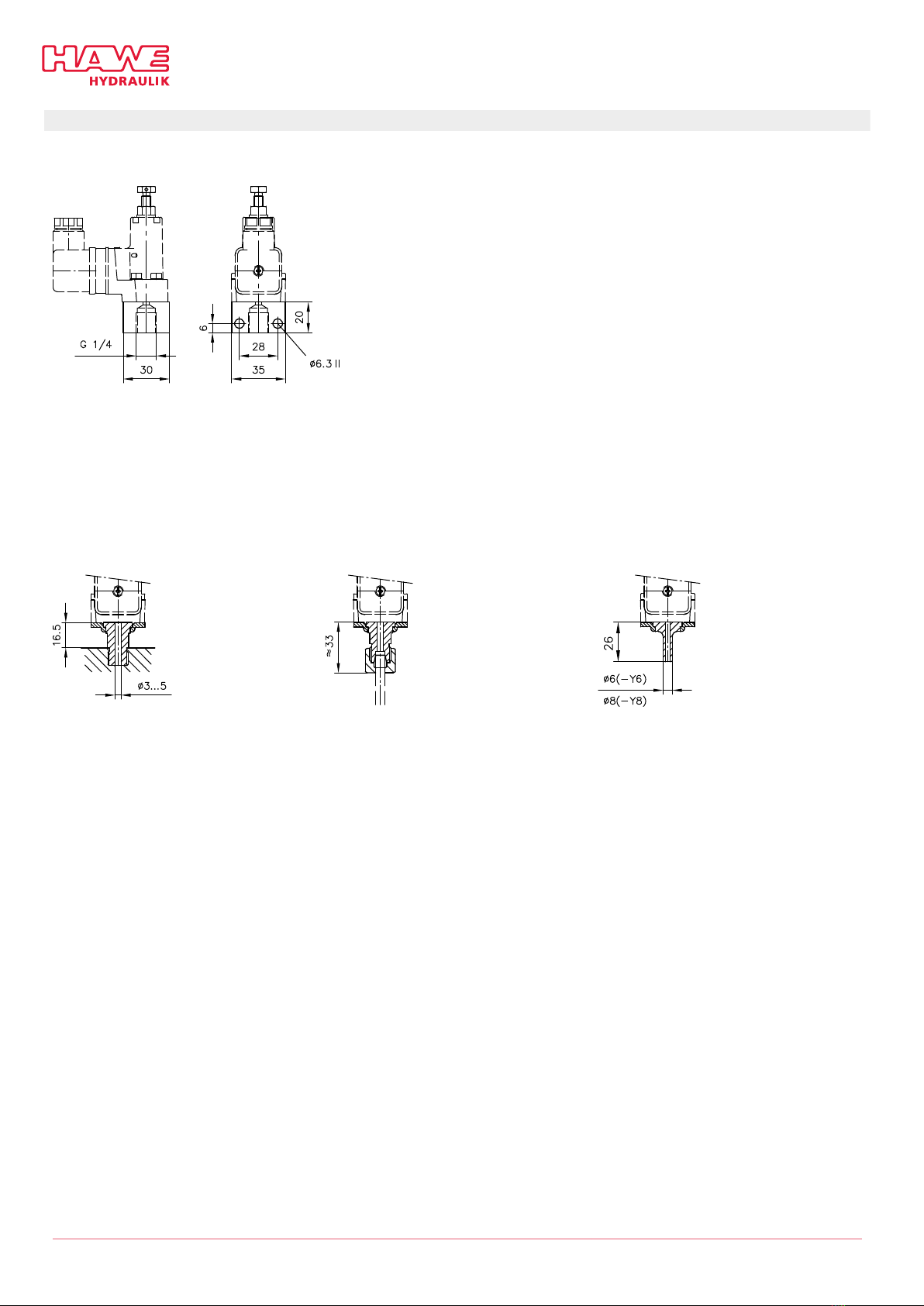
Hy raulic connection
DG 3.. - 1/4
DG 3.. - Y1 (G 1/4 (BSPP))
DG 3.. - Y2 (M12x1.5)
DG 3.. - Y3 (G 1/8 (BSPP))
DG 3.. - YS6
DG 3.. - YS8
DG 3.. - Y6
DG 3.. - Y8
Tapped journal with sealing edge Pipe connection with EO progressive ring
and union nut
Pipe connection pieces
DG 3.. can be rotated in any direction around the pipe axis after loosening the clamping plate (by loosening M4).
16/21 D 5440 - 10-2020-1.1 © HAWE Hydraulik SE
5Assembly, operation an maintenance recommen ations
5.1 Inten e use
This productis exclusively intended for hydraulic applications (uid engineering).
The user must observe the safety measures and warnings in this documentation.
Essential requirements for the pro uct to function correctly an safely:
– All information in this documentation must be observed. This applies in particular to all safety measures and warnings.
– The product must only be assembled and put into operation by qualied personnel.
– The product must only be operated within the specied technical parameters. The technical parameters are described in detail in this
documentation.
– All components must be suitable for the operating conditions in the event of application in an assembly.
– The operating and maintenance manual of the components, assemblies and the specic complete system must also always be
observed.
If the product can no longer be operated safely:
1. Remove the product from operation and mark it accordingly.
✓It is then not permitted to continue using or operating the product.
5.2 Assembly information
The product must only be installed in the complete system with standard and compliant connection components (screw ttings, hoses,
pipes, xtures etc.).
The product must be shut down correctly prior to dismounting (in particular in combination with hydraulic accumulators).
DANGER
Risk to life cause by su en movement of the hy raulic rives when ismantle incorrectly!
Risk of serious injury or death.
■Depressurise the hydraulic system.
■Perform safety measures in preparation for maintenance.
5.2.1 Preparing the base plate for DG 3
See description in Chapter 4, "Dimensions".
© HAWE Hydraulik SE D 5440 - 10-2020-1.1 1 /21

5.3 Operating instructions
Purity an ltering of the hy raulic ui
Fine contamination can significantly impair the function of the hydraulic component. Contamination can cause irreparable damage.
Examples of ne contamination inclu e:
– Metal chips
– Rubber particles from hoses and seals
– Dirt due to assembly and maintenance
– Mechanical debris
– Chemical ageing of the hydraulic uid
NOTE
New hydraulic uid from the manufacturer does not necessarily have the required level of purity.
The hydraulic uid must be ltered during lling.
Pay attention to the cleanliness level of the hydraulic uid to maintain faultless operation.
(Also see cleanliness level in Chapter 3, "Parameters").
Additionally applicable document: D 5488/1 Oil recommendations
5.4 Maintenance information
Conduct a visual inspection at regular intervals, but at least once per year, to check if the hydraulic connections are damaged. If
external leakages are found, shut down and repair the system.
Clean the device surface of dust deposits and dirt at regular intervals, but at least once per year.
18/21 D 5440 - 10-2020-1.1 © HAWE Hydraulik SE
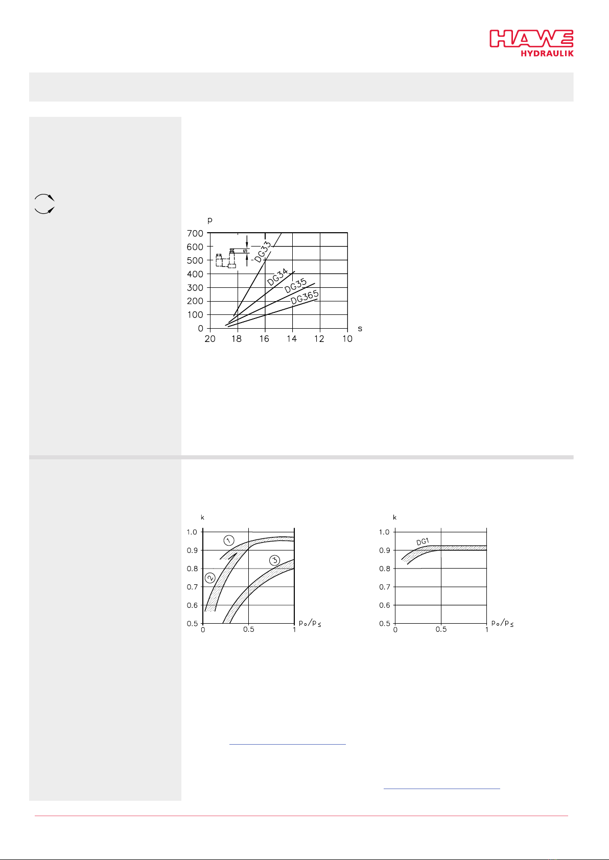
5.5 A justability an switching pressure
A justability
Pressure increases
Pressure rops
When deactivating pumps directly, be aware of a potential afterrun caused by mass action. Also
available for delivery with preset pressure.
Type coding, e.g.
DG 33–600 (setting for increasing pressure)
DG 33–600 F (setting for decreasing pressure)
The tables only contain approximate reference values. Use a pressure gauge to establish a more
accurate switching point!
p pressure setting (bar); s adjustment dimension (mm)
■DG 1 R..: Using a setting knob on the pressure selection scale (there may be slight deviations
between the scale value and the pressure value measured with the pressure gauge).
■DG 3..: With adjusting screw, after unfastening the counter screw (wrench, width across ats 10)
■DG 3..R: By hand with the wing bolt, after unfastening the wing nut
■DG 3..V: With the turn knob
■DG 3..H: With the turn knob, after unlocking (key)
Switching pressures Switching differential between the upper switching point po as the pressure increases and the lower
switching point as the pressure drops.
The calculated pressure value pu = k · po can only be considered an approximate reference value.
po/p Ò set response pressure; k factor
1DG 33, DG 34
2DG 35, DG 364, DG 365
3DG 36
po/p Ò set response pressure; k factor
po= Upper switching point at which the device jumps from its idle position to its switching
position during a pressure increase (response pressure, adjustment range pmin to pmax
"Available versions, main data", Table 1)
pu= Lower switching point at which the device reverts from its switching position back to its
idle position during a pressure drop
pmax = Max. pressure setting in accordance with "Available versions, main data", Table 1
© HAWE Hydraulik SE D 5440 - 10-2020-1.1 19/21

6Other information
6.1 Accessories, spare parts an separate components
Line connectors
Co ing Description Or er co ing
G.. Line connector MSD 3-309
L.. Line connector with LED SVS 296100
L5K - DG Line connector with LED, 5 m cable L5K - DG
L10K - DG Line connector with LED, 10 m cable L10K - DG
SAngled plug for bayonet PA6
Straight plug for bayonet PA6
846 010 A
846 010 B
Co ing Description
K Kostel, 03888005
S Schlemmer, cone with bayonet 10 SL
AMP AMP, AMP Junior 2-pole code number 1
20/21 D 5440 - 10-2020-1.1 © HAWE Hydraulik SE
This manual suits for next models
9
Table of contents


