Hawk Sultan User manual

Table of Contents
Sultan Sonar System
2
Contents
Overview 3
Principle of Operation 3
Benefits 3
Features 3
System Components & Wiring 4
Impact Plate Auto Scum Cleaner 4
AWR234 Wiring 4
AWR234 Amplifier 4
AWRTS Transducer 4
Dimensions 5
AWR234 Remote Amplifier 5
Remote Transducer 5
Impact Plate 5
Dimensions & Mounting Connection 6
Impact Plate Mounting Connection 6
Mounting & Hardware Assembly 7
Impact Plate Assembly 7
*A: Important Cabling Steps to Follow 7
Mounting 8
Transducer Submersion 8
Setup Procedure 9
Powering The Unit 9
Quickset 10
Interface Table 10
Typical High & Low Level 10
Output Adjustment 11
Comms Type 11
Relay Actions 12
Relay Actions 12
Setup Procedure 13
Advanced 13
(1) Gain4 default settings 13
Operating Diagnostics 14
Operating State 14
Communications 15
Modbus 15
HART 16
Profibus PA / Foundation Fieldbus 16
DeviceNet 17
Profibus DP 18
Troubleshooting 19
Unit is measuring incorrect depth or height 19
Error Codes 01 - 04 19
PLC indication does not match measurement 19
Error Codes 08 - 11 & 13 20
Unit Specs & Checks 20
Part Numbering 21
Amplifier 21
Remote Sonar Transducer 22
Scum Cleaner 22
Accessories 23
Specications 24
>
<

Sultan Sonar System
Overview
3
Principle of Operation
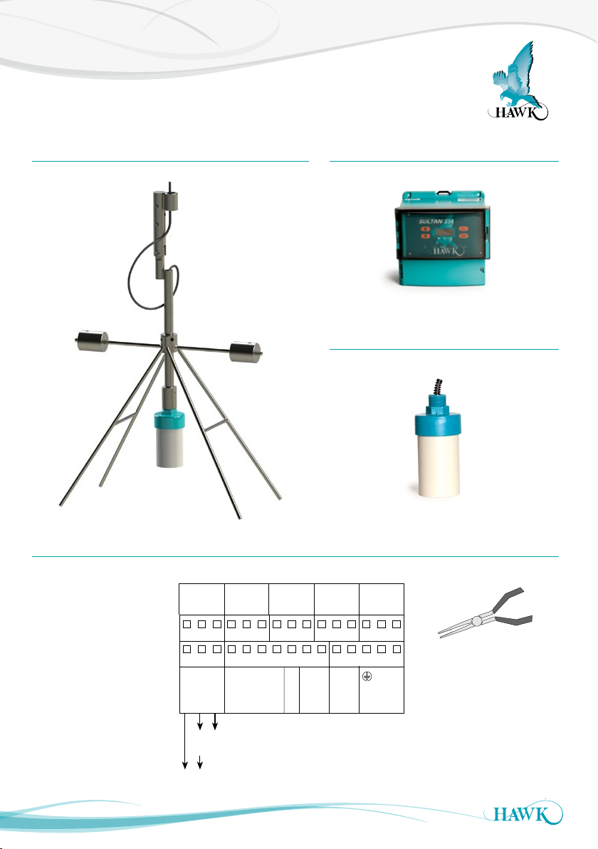
The Hawk Sultan Sonar uses state of the art Sonar technology to measure and control Waste Water
Clarifiers and Thickeners.
The system is easy to use and the innovative design provides critical plant control to optimize performance.
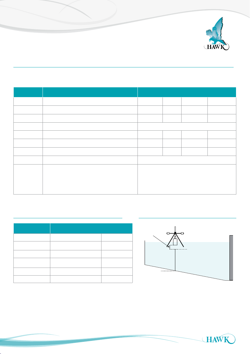
In the water, wastewater industry process conditions will vary greatly between a primary sedimentation tank,
secondary / final clarifier and a gravity thickener. Thickener bed levels, secondary RAS blanket, flocculent
blanket etc, all have different densities and the water above these interface levels are subject to different
process conditions that change.
To optimize performance in each interface application under all process environments:
HAWK has developed a low frequency transducer to penetrate through the suspended solids and capable of
measuring the lightest floc using one single transducer.
To optimize performance under all process environments in each interface application:
HAWK uses one transducer with a frequency and power level that is applicable to the density of the interface
and process conditions expected in the tank. Also, HAWK can guarantee performance for controlling pumps
etc, rather than for monitoring purposes only.
• Simple and easy calibration to track specic densities
• Tune Sensor to 5 preset factory densities or ne tune
to the required density in-situ
• Sonar transducer developed to optimize detection of
heavy and light density interfaces
• Easy calibration to track specic density interfaces,
eg: RAS blanket - 4g/l, oc / uff layer - 1g/l, Bed 10g/l+
• Industrial scum cleaning mechanisms that do not
require maintenance
• No wiper blade assemblies
• Wide range of communications: Modbus, HART,
Foundation Fieldbus, DeviceNet, Probus DP and
Probus PA
• 3G remote support capability for calibration,
commissioning or technical back-up from
HAWK Service Engineer
• 5 Relay alarms
• 1640 feet (500 metre) separation possible between
transducer and Sultan Sonar transmitter.
Benets
• Improved efficiency and control of the
treatment process
• Fully automated plant systems with reliable blanket
level monitoring
• Advanced warning of biological upset or hydraulic
in-balance
• Reduced maintenance with 5 year cleaning
mechanism warranty (no blades to replace)
• Reduced site operational costs significantly with
improved process control
• Improved health and safety on site
(no manual dips required).
Features
>
<

System Components & Wiring
Sultan Sonar System
4
Impact Plate Auto Scum Cleaner
AWRTS Transducer
AWR234Amplier
AWR234 Wiring
Inputs model dependant
Sourcing 4-20mA from Sultan
Sinking 4-20mA
from user device
OR
+–
A
1L
+
–
N
B
RED
BLACK
BLUE
WHITE
Test In
Is
TRANSDUCER DC-In AC- In*4-20mA
COMMS
RELAY 1
NC
COM
NO
RELAY 2
NC
COM
NO
RELAY 3
NC
COM
NO
RELAY 4
NC
COM
NO
RELAY 5
NC
COM
NO
1 2 3 4 5 6 7 8 9 10 11 12 13 14 15
16 17 18 19 20 21 22 23 24 25 26 27 28 29 30
*36-60VDC Sultan version will
have these terminals marked
as the 36-60VDC input
Use long nose pliers
to extract terminals
>
<

Dimensions
Sultan Sonar System
5
Remote Transducer
14 mm (0.6”)
74 mm (2.9”)
78 mm (3.1”)
107 mm (4.2”)
111.5 mm (4.4”)
4 mm (0.2”)
50 mm (2”)
131.5 mm (5.2”)
7.5 mm (0.3”)
192.5 mm (7.6”)
141.5 mm (5.6”)
190 mm (7.5”)
182.5 mm (7.2”)
147 mm (5.8”)
167.5 mm (6.6”)
147 mm (5.8”)
30.7 mm (1.2”)
158 mm (6.2”)
108 mm (4.3”)
190 mm (7.5”)
174 mm (6.9”)
192.5 mm (7.6”)
182.5 mm (7.2”)
30.0
20
.
2
33.029.029.033.0
1
6
.
2
AWR234RemoteAmplier
75mm (2.9")
135mm (5.3")
1" BSP Nipple
588mm
605mm
300mm
588mm
605mm
300mm
Impact Plate
>
<

Dimensions & Mounting Connection
Sultan Sonar System
6
Impact Plate Mounting Connection
The top of the Impact Plate has 3 x 7mm bolt holes
which can be secured to an angle iron or equivalent
bracket. There is also a M25 (1.5”) threaded
connection for a mounting pole connection. The
Impact Plate is designed to swing parallel with the
counter weights. The surface sweeper must come
in contact with the legs of the Impact Plate which
swings the bracket lifting the transducer out of the
liquid. When the sweeper has cleared, it will drop
back in and use the counter weights to re-center. The
force of the movement will clear the sensor face of
any build up
Impact Plate Connection Point
Angle iron or equivalent
Swing
Bolt
90mm (3.54”)
50mm (1.97”)
7.00
(0.79”)
×3
M25 x 1.5 INT
THD THRU
ISOVIEW FOR
REFERENCE ONLY
>
<

Mounting & Hardware Assembly
Sultan Sonar System
7
Impact Plate Assembly
1
2
3
4
5
6
7
8
9
10
11
12
No. Description
QTY.
1
Impact Plate Dual Direction
1
2
Sonar Pole Adaptor
1
3
Impact Plate Counter Balance
1
4
Sonar Male Clevis Assembly
1
5
Sonar Female Clevis Assembly
1
6
M6×45 Stainless Steel Bolt
3
7
M10×40 Stainless Steel Bolt
1
8
M10×12 Stainless Steel Set Screw
4
9
M10×20 Stainless Steel Set Screw
2
10
M6 Stainless Steel Nut
3
11
M10 Stainless Steel Nyloc Nut
1
12
M10 Stainless Steel Washer
1
170mm
Right
30mm
Front
60mm
mm03
Back
160mm
550mm
Allow 550mm loose
cable
to perform the
looping of the cable
Use electrical tape to
hold cable in place
*A: Important Cabling Steps to Follow
*A
>
<

Mounting
Sultan Sonar System
8
Wrap cable entry and
lower connection cable
with Teflon tape
Transducer Submersion
• The transducer should be half submerged in the liquid and mounted 1/3rd radius from the feedwell
to the launder
• Avoid mounting in the proximity of a feedwell.
• Impact Plate must make contact with surface sweeper
High Level
20mA
0.500m
Low Level
4mA
X.xxm
Blanking /
non-measured
zone
1/2 Submerged
1/3 Radius
>
<

Setup Procedure
Sultan Sonar System
9
CAL
Height/Depth
CAL
Unlock 0
Quickset
CAL
App Type
CAL
App Type
*Edit*
Density
Switch
Blocked Chute
Boom Protect
Alignment
Output Adj Advanced*
Advanced
(Tx Setup)
*Also Tx Setup
Operating Diagnostic Display
Unlock Code (default 0)
Main Menus
Amplifier /
Application
settings
Comms / Output
Settings
Transducer
settings.
Powering The Unit
When power is applied the unit will start up automatically. It will scroll through its boot diagnostics and display
the serial numbers, software version and model types for the amplifier and transducer
The unit will display its default operating screen ‘Height’ or ‘Depth’ with a measurement. The unit will re-scan
for the level whenever it is powered up.
The sensor face must be submerged in liquid in order to operate correctly.
CAL
RUN
CAL for select / proceed / edit
Arrows to scroll / adjust
RUN to re-active unit
*Do not adjust Advanced settings without expert knowledge
>
<

Setup Procedure
Sultan Sonar System
10
1/3 Radius
1/2 Submerged
High Level
20mA
0.500m
Low Level
4mA
X.xxm
Blanking /
non-measured
zone
Typical installation - Set ‘Low Level’ (4mA) to
be the distance from the transducer face to the
bottom of the tank. High Level should be 0.500m
for most accurate and reliable measurement.
Parameter Description Options
Unit Adjust displayed measurement unit Inches Feet Meters Centimeters
Low Level Set Low level measurement point (4mA) Adjustable
High Level Set High level measurement point (20mA) Adjustable
Blanking Non-Measured zone Adjustable (recommended default 350mm)
Damping Adjust output response time & smoothness Adjustable
Failsafe Set failsafe output & timer 20mA 4mA LastKnown 20.20mA
DispMode Set LCD measurement display mode Height Depth
Interface Select preferred interface density Adjustable grams per liter (see Interface Table
Fine Adj
• Manually fine tune sensor for required density
• Higher value for lighter densities
• Press CAL to fire a test pulse which will
return the depth measurement.
Adjustable
• After selecting Interface pre-set you can also use ‘Fine Adj’ to
fine tune calibration.
• Fire several test pulses to attain a good sample size.
• If ‘Fine Adj’ is reduced to 0%, select a lighter Density
Quickset
The Quickset menu contains the basic parameters required to get the unit up and running.
It is one of the three main menu options in the internal software.
Interface Table
Interface g/l Typical Applications
0.1 - 0.6 Lighter layers
0.6 - 1.2 Hindered layer Settling layer
1.2 - 3.0 RAS
3.0 to 6.0 RAS Bed
6 to 10 Bed
10+ Bed / Heavy sludge
Typical High & Low Level
>
<

Setup Procedure
Sultan Sonar System
11
Output Adjustment
The Output Adj menu contains parameters related to adjusting analogue, switch & communication protocol
relayed settings.
Parameter Description Options
4mA Adj Fine tune the 4mA output current Adjustable
20mA Adj Fine tune the 20mA output current Adjustable
Analog Invert analogue from 4-20mA to
20-4mA 4-20mA 20-4mA
Simulate
A simulated distance reading is
transmitted as analogue (distance
measured from sensor face)
Adjustable
Comm Type
• Adjust communication protocol
settings.
• Standard Analogue and Switch
models include Modbus as default.
Modbus* HART* Profibus
(DP)* DeviceNet* FF/
PA*
RlyMod 1-5 Configure Relay actions De-energise** Energise** Failsafe** Off**
Bk Light Turn LCD back light on or off On / Off
V in Chk
V in Chk will trigger failsafe relay
if voltage supply to the unit falls
below minimum requirement.
On / Off
*See ‘Comms Type **See ‘Relay Actions’
Comms Type
Sub-Menu Description Options
DeviceID
Adjust unit device ID for
Modbus, HART, Profibus
DP
1-255
FBusAdd Adjust unit Device ID for
FF/PA, DeviceNet 1-255
BaudRate Adjust comms network
speed
Comms
dependant
>
<

Relay Actions
Sultan Sonar System
12
Set Relay Parameters in Output Adjustment menu
The two relay levels are RlyL1 and RlyL2
The display will show RlyL1 1, the last 1 indicated the
Relay number (eg 1 to 5)
L1 and L2 distances are measured from the
transducer face
L1 must be equal to or less than L2.
Energise
EN
DeEnergise
DEN
NC NOCOM NC NOCOM
NC NOCOM
State 1
State 2
Relay Action
FailSafe
FS
FailSafe
FS
NC NOCOM
Relay Status
LED Status
Remote Amplifier
terminal function
labels
NC NOCOM
NC NOCOM
NC NOCOM
NC NOCOM
NC NOCOMNC NOCOM
system operating
normally
OFF
power/system/
measurement failure
Below L2 or
RISING LEVEL
L1
L2
between L1 and
L2 after passing
below L2.
LOW LEVEL or
Above L1 or
FALLING LEVEL
L1
L2
between L1 and
L2 after passing
above L1.
HIGH LEVEL or
POWER FAILURE
NC NOCOM NC NOCOM NC NOCOM NC NOCOM NC NOCOM
Relay Actions
Sub-Menu Description Options
R ly L1 1- 5 Adjust Relay switch point
(L1 must be < L2) Adjustable
RlyL2 1-5 Adjust Relay switch point
(L2 must be > L1) Adjustable
>
<

Setup Procedure
Sultan Sonar System
13
Advanced
The Advanced menu contains parameters for Gain control, manually adjustment of speed of sound, offset and
restoring the amplifier and transducer to their default state.
These settings typically do not require adjustment unless there are special circumstances. Do not adjust
Advanced settings without expert knowledge or consulting your local representation.
Parameter Description Options
Gain4 Primary sensitivity adjustment. This value is automatically(1) set by the
selected Interface range in Quickset. Higher values for lighter densities. Adjustable
GainStep3 Adjustment of sensitivity for DistStep3 zone. Adjustable
DistStep3 Depth of zone measured from the sensor face for non-variable GainStep3. Adjustable
Threshold Minimum echo size which the unit will accept as a valid echo Adjustable
EmptyDist Unit will not consider any echoes beyond this distance valid.
This is automatically calculated by the ‘Low Level’ parameter. Adjustable
Temp Trim Create manual measurement offset for a specific temperature. Adjustable
Dist Trim Create manual measurement offset for a specific distance. Adjustable
Velocity Adjusts the internal speed of sound calculation. 1.0000 is speed of sound
through water Adjustable
(1) Gain4 default settings
Interface Selected (g/l) Default Value
0.1 - 0.6 24.9%
0.6-1.2 14.9%
1.2-3.0 10.0%
3.0-6.0 4.9%
6.0-10.0 2.0%
10+ 1.1%
>
<

Operating Diagnostics
Sultan Sonar System
14
Operating State
In this operational state you can use the
Space
2.622m
Matrl%
74.0%
buttons to navigate through and view unit diagnostics and other
measurements.
Diagnostic Typical Reading Description
Bed
Distance
Bed indicates Bed height measured from Low Level
Level Depth indicates depth of measured Density measured from the
transducer face
Bed% %
Tx 1Transducer 1
Normal
Distance
Unit is operating normally
Recover Unit is searching for new signal
Failed Unit is in failsafe mode
W (down) Distance Tracking Window end point (measured from sensor face)
W (up) Distance Tracking Window start point (measured from sensor face)
T: 23.8 Measured Temperature
N: 0.00% Noise (electrical and frequency interference)
R: 0.00% Current Recover Gain added
G: 44.6% Total amount of Gain applied to track current echo
S: 2.49V Signal size in Volts
E: Distance Non-damped measured distance measured from sensor face down
>
<

Communications
Sultan Sonar System
15
Protocol: Modbus RTU (2 wire)
Speed: 19200 Baud
Data bits: 8
Parity: None
Stop Bits: 1
HAWK Sultan series units act as ‘slave’ devices on a
Modbus network.
Units are shipped from the factory with a default
Modbus address of 1. The Modbus address of any
unit can be changed individually if units are to be
connected in a multi-drop network. Each address
number must only be used once on any network
(possible addresses are 1-255).
Diagnostic Block (Read Only): *Can be read as
Singles or any Block wholly within the limits of this
range of addresses*
40123 - LOW LEVEL span set point in mm
40124 - HIGH LEVEL span set point in mm
40125 - DISPLAYED DISTANCE (DISTANCE) in mm
40127 - NEW DISTANCE (E-DISTANCE) in mm
40128 - CONFIRM DISTANCE (C-DISTANCE) in mm
40129 - ECHO SIZE in Volts/102
40130 - GAIN at Echo detection point in %/7.5
40131 - NOT USED (Gain Limit)
40132 - RECOVER GAIN in %/7.5
40133 - NOISE in %/7.5
40134 - TEMPERATURE in Degrees K/10
((DegreesC - 273.2)/10)
40136 - CONFIRM COUNTER current value
40137 - HOLD COUNTER current value
40139 - WINDOW FORWARD POSITION in mm
40140 - WINDOW BACK POSITION in mm
Span Adjustment (Read/Write) MUST Read/Write
SINGLES-NOT BLOCKS:
40012 - LOW LEVEL span set point in mm
40013 - HIGH LEVEL span set point in mm
Relay Function Adjustment (Read/Write)
MUST Read/Write SINGLES-NOT BLOCKS:
40051 - Relay 1 Mode setting
0-OFF
1-FS (Failsafe)
2-EN (Energise on Level)
3-DEN (De-Energise on Level)
40052 - Relay 2 Mode setting (see Relay 1)
40053 - Relay 3 Mode setting (see Relay 1)
40054 - Relay 4 Mode setting (see Relay 1)
40055 - Relay 5 Mode setting (see Relay 1)
40035 - Relay 1 L1 set point in mm
40036 - Relay 1 L2 set point in mm
40037 - Relay 2 L1 set point in mm
40038 - Relay 2 L2 set point in mm
40039 - Relay 3 L1 set point in mm
40040 - Relay 3 L2 set point in mm
40041 - Relay 4 L1 set point in mm
40042 - Relay 4 L2 set point in mm
40043 - Relay 5 L1 set point in mm
40044 - Relay 5 L2 set point in mm
Modbus
>
<

Communications
Sultan Sonar System
16
Extended Parameters (Read/Write) *MUST Read/
Write SINGLES-NOT BLOCKS*:
40059 - DISPLAY UNITS
3-Millimetres
4-Centimetres
5-Metres
6-Feet
7-Inches
40014 - FAILSAFE MODE
0 - 3.5mA
1 - 3.8mA
2 - 20.2mA
3- Last Known
4 - 4.0mA
5 - 20.0mA
40015 - FAILSAFE TIME (seconds)
40016 - DENSITY SELECTION
1 - 0.1 - 0.6g/l
2 - 0.6 - 1.2g/l
3 - 1.2 - 3g/l
4 - 3.0 - 6.0g/l
5 - 6.0 - 10.0g/l
6 - 10.0+g/l
40019 - DISPLAY MODE
3 - Material %
4 - Height
5 - Depth
40032 - OFFSET (mm)
40020 - LOCK CODE
40021 - FILL DAMPING
40022 - EMPTY DAMPING
40063 - ANALOG
0 - 4-20mA (4mA low, 20mA high - standard)
1 - 20-4mA (20mA low, 4mA high - inverted)
40432 - Fine Adj in %/7.5
40447 - GAIN parameter setting in %/7.5
40448 - GAIN STEP in %/7.5
40449 - DISTANCE STEP (mm)
40450 - THRESHOLD in Volts/100
40451 - BLANKING (mm)
40452 - EMPTY DISTANCE (mm)
40452 - VELOCITY /10000
Modbus
HART
Basic functions / commands only
PV Measurement
Measured Units
Analog Value
Percent Range
Upper Range Value
Lower Range Value
Damping
Foundation Fieldbus and Profibus PA have stand
alone manuals located in the downloads-manuals
section of www.hawkmeasure.com
ProbusPA/FoundationFieldbus
>
<

Communications
Sultan Sonar System
17
Setting the Baud Rate and the
DeviceNet Address
The DeviceNet factory default of Baud Rate and
FBus Address are 125kbps and 63 in a Sultan unit
with. To modify these values follow the instructions
below.
1. Go to the ‘Output Ad’ menu
2. Use the Up and Down push buttons to reach the
CommType parameter
3. Make sure that the CommType is set to
‘DeviceNet’
4. Press the CAL button twice
5. DeviceID will be displayed - this ID is for Modbus
networking, do not adjust.
6. Use the Down push button to reach the
BaudRate parameter
7. The default value for the BaudRate is 125kpbs.
Press CAL button and use the Up and Down push
buttons to modify this value
8. Press CAL button when finished
9. Use the Down push button to reach the FBusAdds.
The default value of the FieldBus Address is 63.
Press CAL button and use the Up and Down push
buttons to modify this value
10. Press CAL button again when finished
11. Press RUN to save and several times again to
return the unit to operating mode.
Output Data
Profibus/DeviceNet now transmit 18 bytes/9 words,
description of the words is as follows (For firmware
version 5.54 and above).
1. Displayed Distance
(Space Distance is the Primary Variable)
2. Percentage (Percent of Range)
3. Hi Level (Upper Range)
4. Low Level (Lower Range)
5. Status Flags
Bit0 = Echo was received inside the span.
Bit1 = Echo is Confirmed.
Bit3 = Searching is searching for an Echo.
BitF = Unit has Failed to detect an Echo.
6. Displayed Distance2 (Second/Differential Variable)
7. Percentage2 (Second/Differential Variable)
Integral
Bit F Bit E Bit 3 Bit 1 Bit 0
Failed ~~~~~ Search 0 Echo Cfm : 1 = , True, 0 = False Echo R : 1 = , True, 0 = False
AC-IN DEVNET DC-IN
TEST
DEVNET COMMS RL1
24V+shld GND
5. V+
4. CAN_H
3. SHEILD
2. CAN_L
1. V-
ABshld NC COM NO
ABshld
LI N -+
AC-IN DEVNET DC-IN
TEST
DEVNET COMMS RL1
24V+shld GND
5. V+
4. CAN_H
3. SHEILD
2. CAN_L
1. V-
ABshld NC COM NO
ABshld
LI N -+
Remote
DeviceNet
>
<

Communications
Sultan Sonar System
18
SettingtheProbusDPAddress
Factory defaults of FBusAdds is 126 in a Sultan unit
with Profibus CommType. To modify this value follow
the instruction below:
1. Go to the ‘Output Ad’ menu
2. Use the Up and Down push buttons to reach the
CommType parameter
3. Make sure that the CommType is set to ‘Profibus’
4. Press the CAL button twice
5. DeviceID will be displayed - this ID is for Modbus
networking, do not adjust.
6. Use the Down push button to view the BaudRate
parameter. The value for the BaudRate is selected
automatically and can not be modified.
8. Use the Down push button to reach the FBusAdds.
The default value of the FieldBus Address is 126.
Press CAL button and use the Up and Down push
buttons to modify this value.
9. Press CAL button again when finish.
10. Press RUN several times to return the unit to
operating mode.
Output Data
DeviceNet now transmits 18 bytes/9 words,
description of the words is as follows (For firmware
version 5.54 and above)
1. Displayed Distance
(Space Distance is the Primary Variable)
2. Percentage (Percent of Range)
3. Hi Level (Upper Range)
4. Low Level (Lower Range)
5. Status Flags
Bit0 = Echo was received inside the span.
Bit1 = Echo is Confirmed.
Bit3 = Searching is searching for an Echo.
BitF = Unit has Failed to detect an Echo.
6. Displayed Distance2 (Second Variable)*
7. Percentage2 (Second Percent of Range)*
*Used for Differential output
Wiring
5. B IN
4. A IN
3. SHEILD
2. B OUT
1. A OUT
ProbusDP
>
<

Troubleshooting
Sultan Sonar System
19
Error Codes 01 - 04
Error 01
Amplifier/Transmitter can not communicate with
transducer.
• Wiring: Check the terminals for a loose or
incorrect connection (including junction box/cable
extensions)
• Check the cables for any signs of damage
• Ensure any customer supplied cable meets
HAWK specifications
• If using junction box extension trace the 8-10VDC
from the red/black amplifier terminals to
the transducer to ensure wires are correct
• If using a junction box ensure you follow HAWK
specification for extending cable
• ‘Unit Specs & Checks’ has additional checks for
causes of Error 01.
Error 02
Communication data corruption between
Transmitter and Transducer.
• It can be a result of noise in data lines or one of
data lines (white or blue) being open circuit.
• Make sure wiring is correct especially look to the
screen (earth).
• Ensure you are using quality shielded
instrument cable.
• ‘Unit Specs & Checks’ has additional checks for
causes of Error 02.
Error 03
• Specific comms mode is selected (eg Profibus, FF)
but comms module is not connected or responding
• Check your unit part number to ensure it has
correct comms
• If you do not have additional comms
(part number option X) then select Modbus.
Error 04
Amplifier is programmed with incorrect software
or has wrong hardware connected.
• Contact your local support.
Unit is measuring incorrect depth or height
• Confirm display mode is correct (Depth is measured
from sensor face to target. Height is measured from
low level to target.
• Confirm High Level and Low Level match application
requirement.
• Increase or decrease selected 'Density'. A higher
Density value programs the unit to look for a more
dense layer deeper.
• High volumes of poor settling or suspended material
with attenuate the Sonar pulse. The unit may
read higher tracking suspended material if process
conditions in the tank fail.
PLC indication does not match measurement
• Disconnect the analogue wires from the amplifier.
Use a multimeter on the 4-20mA terminals labeled
IS and + to read the direct mA from the unit. Re-
connected analogue wires and compare this value
with the reading from the control system.
• Confirm High Level and Low Level are set to the
same values in amplifier and control system.
>
<

Troubleshooting
Sultan Sonar System
20
Unit Specs & Checks
Sultan 234
Specified ranges (supply dependant): 90-260VAC,
12-30VDC, 30-48VDC). For suspected power issues
ensure user supply is appropriate & consistent.
If using AC power you can check the power supply
for faults by reading the DC +/- terminals with a
multimeter set to DC. This terminal will produce 15-
16VDC stable. If this value is lower or inconsistent
you may a problem with the internal power supply.
Unit performance will be affected if the unit detects
voltage below 9VDC. If ‘V in chk’ is on the unit will
trigger its failsafe routine. If V in chk is off the unit will
display V fail on the LCD.
Transducers
The Transducer power (red wire) should draw
8-10VDC. If this figure is too high or too low check
Sultan power & supplied power as above.
Disconnect transducer from amplifier.
There should be no open circuits between wires.
Resistances between transducer wires (approximate
values):
If any are open circuit check wiring connections or
there may be a problem with the transducer.
Transducer problems may exhibit via the amplifier
protecting itself against high current draw - measure
resistance across transducer: Red and DC:+
terminals on the amplifier while the transducer
disconnected and then connected. If the resistance
increases dramatically there is potentially a wiring or
transducer problem.
Blue - White 32Kohms
Black - Blue 15.6Kohms
Black - Red 1-2Mohm (or OV / high resistance)
Black - White 15.6Kohms
Error Codes 08 - 11 & 13
Error 08
Transducer type mismatch.
Error 09
NV ram corrupted.
Error 10
NV write error
Error 11
Transducer no. 2 communication error (cannot talk to
the sensor)
Error 13
Voltage error. Input voltage too low or voltage error.
>
<
Table of contents
Other Hawk Sonar manuals