Hawker Freedom User manual
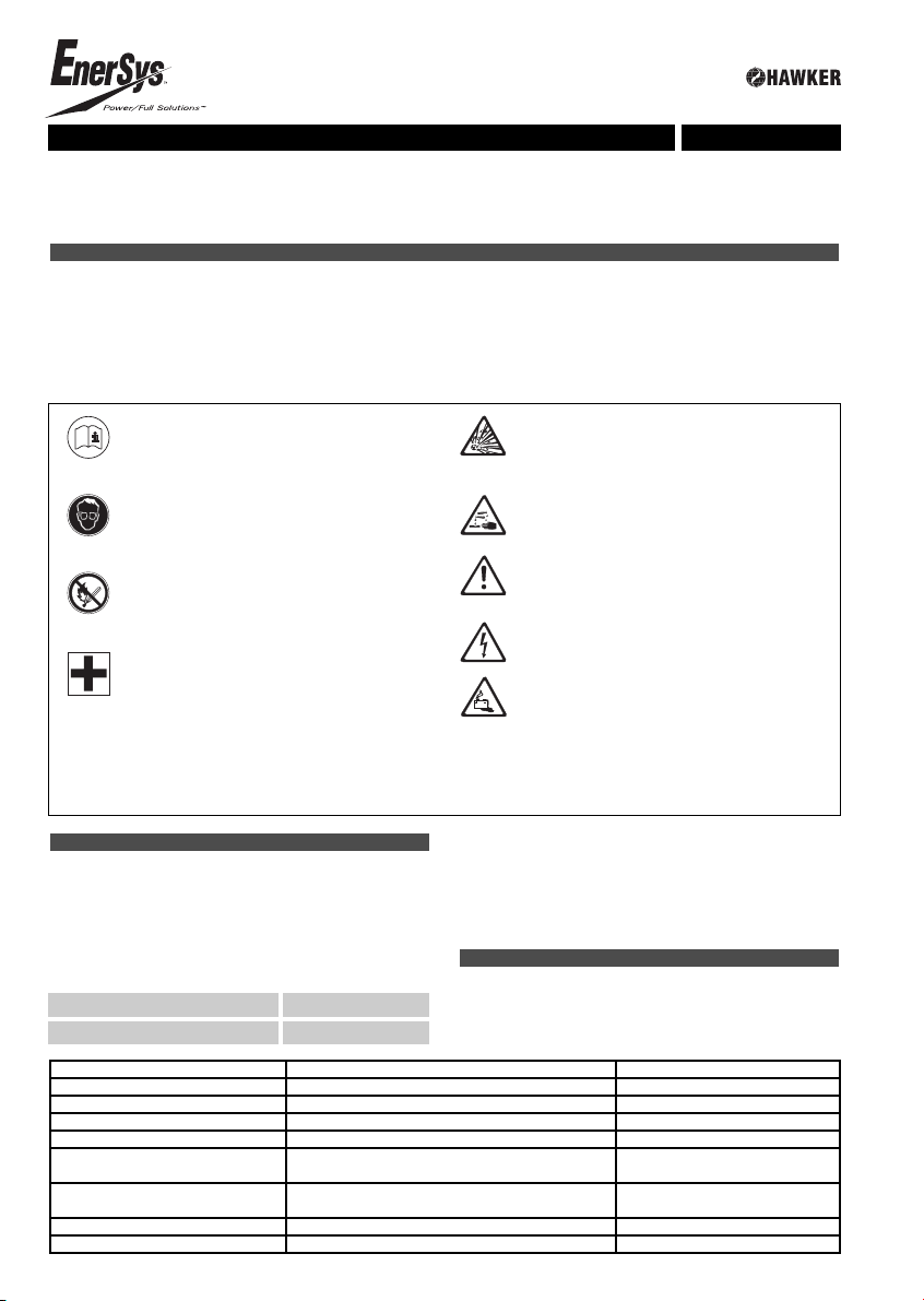
•Pay attention to the operation instruction and
fix them close to the battery.
•Work on batteries to be carried out by skilled
personnel only!
•Use protective glasses and clothes when
working on batteries. Pay attention to the
accident prevention rules as well as
EN 50272-3 and EN 50110-1.
•No smoking!
•Do not expose batteries to naked flames,
glowing embers or sparks, as it may cause
the battery to explode.
•Acid splashes in the eyes or on the skin must
be washed with water. In case of accident
consult a doctor immediately!
•Clothing contaminated by acid should be
washed in water.
•Risk of explosion and fire, avoid short circuits!
•Caution: Metal parts of the battery are always
live. Do not place tools or other metal objects
on the battery!
•Electrolyte is highly corrosive.
•Batteries and cells are heavy. Ensure secure
installation!
•Useonly suitable handling equipment
•Dangerous electrical voltage!
•Pay attention to the hazards that can be
caused by batteries
ENGLISH
Instructions for use Hawker freedom system
Ignoring the operation instructions, repair with non-original parts or using additives for the electrolyte will render
the warranty void.
The Hawker freedom system integrates a battery with airmixing system, an on-board electronic device, the easyplus, for
checking temperature, electrolyte level and voltage balance, and for recording data on capacity and battery, this permitting
the communication with the HF charger, a Powertech easy.com charger (for instructions concerning the charger, please read
specific manual)
Rating Data
1. Nominal capacity C5: See type plate
2. Nominal voltage : 2.0 V x No of cells
3. Discharge current : C5/5h
4. Nominal S.G. of electrolyte* : 1.29 kg/l
5. Rated temperature : 30°C
6. Nominal electrolyte level : up to electrolyte level mark ”max.”
*Will be reached within the first 10 cycles.
1. Commissioning filled and charged batteries
(For commissioning of unfilled batteries see separate
instructions!)
The battery should be inspected to ensure it is in perfect
physical condition.
The charger cables must be connected to ensure a good
contact, taking care that the polarity is correct. Otherwise
battery, vehicle or charger could be damaged. The specified
torque loading for the polscrews of the charger cables and
connectors are:
steel
M 10 perfect connector 25 ± 2 Nm
The level of the electrolyte must be checked. If it is below
the anti-surge baffle or the top of the separator it must first
be topped up to this height with distilled or demineralised
water (DIN 43530 part 4).
The battery is then charged as in item 2.2. The electrolyte
should be topped up to the specified level with distilled or
demineralised water.
2. Operation
EN 50272-3 “Traction batteries for industrial trucks” is the
standard which applies to the operation traction batteries
in industrial trucks.
In normal working condition, the green LED on easyplus
must be ON, with fixed or flashing light.
LED DEFINITION ACTION
Off No power Check connection
Green LED flashing (slowly) Power and Hardware OK
Fixed green LED Complete charge
Fixed red LED Overdischarge Charge immediately
Red LED flashing Excessive temperature Cool down til normal
temperature is reached
Blue LED flashing (slowiy) Power and Hardware OK for voltage
balance and level indication
Blue LED flashing Difference of voltage balance Hawker Service action
Blue LED ON Low electrolyte level Topping up

The easyplus contains data on the battery (serial number,
capacity, technology), records data during the operation
(number of cycles, temperature, capacity, …) and transmits
the information to the charger with warnings appearing
on the charger’s display. (low electrolyte level, topping up
needed, overdischarge, daily cycle, excessive temperature,
voltage balance anomaly). Some of the information is
already indicated through the LEDs on the top of the
easyplus. When the blue led on easyplus is ON and stays
fixed, topping up must be carried out. Water topping up
should be done latest when the blue LED is ON or after
maximum 200 cycles.
2.1 Discharging
Be sure that all ventilation openings are not sealed or
covered. Electrical connections (e.g. plugs) must only be
made or broken in the open circuit condition. To achieve
the optimum life for the battery, operating discharges of
more than 80% of the rated capacity must be avoided
(deep discharge). This corresponds to an electrolyte specific
gravity of 1.15 kg/l at 30°C at the end of the discharge.
Discharged batteries must be recharged immediately and
must not be left discharged. This also applies to partially
discharged batteries.
2.2 Charging
Only direct current must be used for charging. The Hawker
freedom system is designed with a Hawker HF charger,
Powertech easy.com. In the system, the charger assigned
to the battery has been specifically determined for suiting
the size of the battery.
Hawker freedom batteries are low gas emission, so some
charging gasses are evolved.
Battery container lids and the covers of battery
compartments must be opened or removed.
The ventilation must comply to EN 50272-3 standard.
The vent plugs should stay on the cells and remain closed.
With the charger switched off connect up the battery,
ensuring that the polarity is correct. (positive to positive,
negative to negative). Now switch on the charger. When
charging the temperature of the electrolyte rises by about
10°C, so charging should only begin if the electrolyte
temperature is below 45°C. The electrolyte temperature of
batteries should be at least +10°C before charging otherwise
a full charge will not be achieved.
If a defect signal concerning the pump or the electrolyte
mixing system appears on charger’s display, check that the
piping system is connected and examine the piping circuit
for leaks or defects.(see 3. Maintenance). In the meantime,
the HF charger will adapt the profile.
The air pipe should never be removed during charge.
2.3 Equalising charge
Equalising charges are used to safeguard the life of the
battery and to maintain its capacity. They are necessary
after deep discharges or repeated incomplete recharges.
Equalising charges can be carried out manually, or will
be performed automatically after a rest following normal
charging.
Watch the temperature!
2.4 Temperature
An electrolyte temperature of 30°C is specified as the rated
temperature. Higher temperatures shorten the life of the
battery, lower temperatures reduce the capacity available.
55°C is the upper temperature limit and is not acceptable
as an operating temperature.
A temperature sensor is integrated in the easyplus device.
In case of excessive temperature the red LED is flashing.
Several hours of rest can be necessary to let the battery
cool down and to avoid damage.
2.5 Electrolyte
The rated specific gravity (S. G.) of the electrolyte is related
to a temperature of 30°C and the nominal electrolyte level
in the cell in fully charged condition. Higher temperatures
reduce the specific gravity of the electrolyte, lower
temperatures increase it. The electrolyte must conform
to the purity regulations in DIN 43530 part 2.
3. Maintenance
3.1 Daily
After each recharge, visual inspection after recharging for
signs of dirt and mechanical damage.
3.2 Weekly
Control all indications on easyplus and on charger’s display
for eventual warnings, defects, or need for water topping up
(especially if the battery remains in battery compartment in
the truck).
If the blue LED on the easyplus is ON, the battery needs to
be topped up in the shortest delay. In case of Hawker
Service contract, contact it immediately.
3.3 Annually
In accordance with EN 1175-1 and EN 50272-3 at least once
per year, the insulation resistance of the truck and the
battery must be checked by an electrical specialist.
After approx.200 cycles (one shift operation) or when the
blue LED on the easyplus is ON the Hawker freedom
batteries have to be topped up. In multiple shift and warm
ambient temperature operations, it may be necessary to
have shorter than 200 cycles topping up intervals
If you have a service contract, please contact the Hawker
Service!
After charging has ended the specific gravity and the
temperature of the electrolyte in all cells should be
measured and recorded. If significant changes from earlier
measurements or differences between the cells are found
further testing and maintenance by the service department
should be requested.
The filter of the air pump has to be checked during the
annual maintenance and eventually to be cleaned or
replaced. Earlier replacement of the filter is necessary if,
for undefined reasons (no leaks in the air pipes) the defect
signal of the air mixing system on the charger or on the
battery (on DC air pump or remote signal) is illuminated.
During the annual maintenance, check the correct
operation of the air pump.
4. Care of the battery
The battery should always be kept clean and dry to prevent
tracking currents. Any liquid in the battery tray must be
extracted and disposed of in the prescribed manner.
Damage to the insulation of the tray should be repaired
after cleaning, to ensure that the insulation value complies
with EN 50272-3 and to prevent tray corrosion. Repairs on
batteries have to be performed by Hawker service personnel
only.
5. Storage
If batteries are taken out of service for a lengthy period
they should be stored in the fully charged condition in a dry,
frost-free room. To ensure the battery is always ready for
use a monthly equalising charge as in point 2.3 can be made:
After a maximum of 6 weeks storage, proceed to a full
charge (see 2.2)
The storage time should be taken into account when
considering the life of the battery.
6. Malfunctions
If malfunctions are found on the battery or the charger
our service department should be called in without delay.
A service contract with us will make it easier to detect and
correct faults in good time.
freedom
OPTION
Aquamatic water refilling system (optional accessory)
1. Application
The water refilling system is used to automatically maintain
the nominal electrolyte levels.
2. Function
A valve and a float together control the topping up process
and maintain the correct water level in each cell. The valve
allows the flow of water into each cell and the float closes
the valve when the correct water level has been reached.
For fault-free operation of the water refilling system, please
note the instructions below:
2.1 Manual connection
The battery should be topped up shortly before completion
of a full charge, as at this point the battery has reached a
defined operational state resulting in satisfactory electrolyte
mixing. Filling takes place when the connector (7) from the
tank is connected to the coupling (6) on the battery. The
battery should only be connected to the filling system once
the easyplus BLUE Led is ON, or when.the need for water
topping is appearing on charger display, or when 200 cycles
are reached.
2.1.1. In multiple shift and warm ambient temperature
operations, it may be necessary to have shorter than
200 cycles topping up intervals.
2.2 Filling time
Filling time depends on the utilisation rate and the
corresponding battery temperature. Generally speaking, the
top up process takes some minutes and can vary according
to the battery capacity; after this, if manual filling is being
used, the water supply to the battery should be turned off.
2.3 Working pressure
The water refilling system should be installed in such a way
that a water pressure of 0.2 to 0.6 bar is obtained (with at
least 2 m height difference between the upper edge of the
battery and the lower edge of the tank). Any deviation from
this means that the system will not function properly.
2.4 Purity
The topping up water must be distilled or demineralised.
The water used to refill the batteries must have a
conductance of not more than 30 µS/ cm. The tank and
pipes must be cleaned before operating the system.
2.5 Pipe system on the battery
The plugs of each cell are connected in series or
series/parallel through a piping system.(EN 50272-3)
For safety reasons, the system must not be modified in
any way.
2.6 Working temperature
Batteries fitted with Aquamatic must only be charged
or refilled in a room temperature above 0°C.
2.7 Flow control
A flow indicator built into the water supply pipe to the
battery monitors the filling process. During filling the water
flow causes the built-in disc in the flow indicator to turn.
When all the plugs are closed the disc stops, indicating
that the filling process is complete.
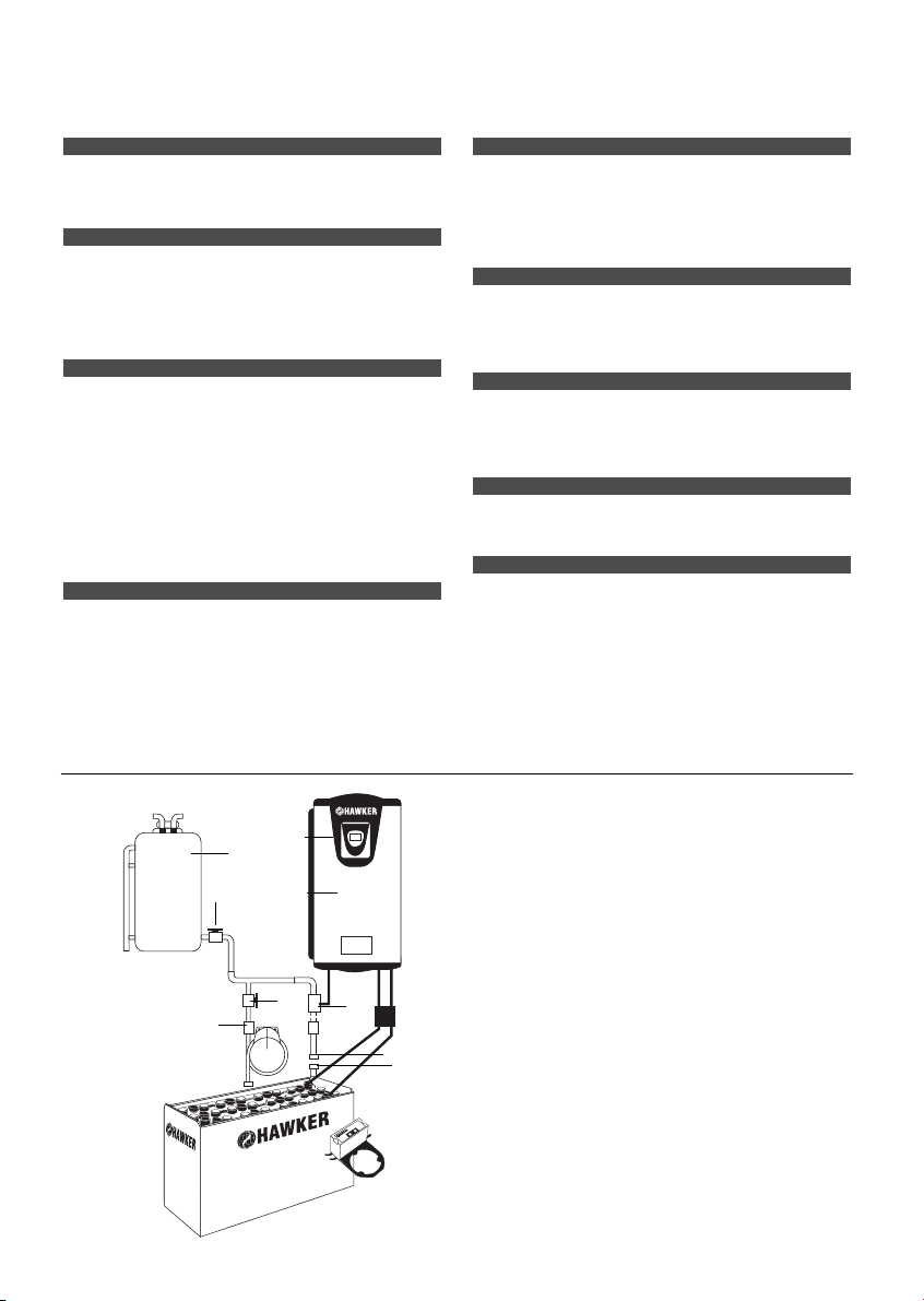
1. tank
2. outflow connector with ball valve
3. plug with magnetic valve
4. plug with ball valve
5. flow control
6. coupling
7. connector
8. battery charger
9. charger main switch
1
2
3
4
5
76
8
9
The easyplus contains data on the battery (serial number,
capacity, technology), records data during the operation
(number of cycles, temperature, capacity, …) and transmits
the information to the charger with warnings appearing
on the charger’s display. (low electrolyte level, topping up
needed, overdischarge, daily cycle, excessive temperature,
voltage balance anomaly). Some of the information is
already indicated through the LEDs on the top of the
easyplus. When the blue led on easyplus is ON and stays
fixed, topping up must be carried out. Water topping up
should be done latest when the blue LED is ON or after
maximum 200 cycles.
2.1 Discharging
Be sure that all ventilation openings are not sealed or
covered. Electrical connections (e.g. plugs) must only be
made or broken in the open circuit condition. To achieve
the optimum life for the battery, operating discharges of
more than 80% of the rated capacity must be avoided
(deep discharge). This corresponds to an electrolyte specific
gravity of 1.15 kg/l at 30°C at the end of the discharge.
Discharged batteries must be recharged immediately and
must not be left discharged. This also applies to partially
discharged batteries.
2.2 Charging
Only direct current must be used for charging. The Hawker
freedom system is designed with a Hawker HF charger,
Powertech easy.com. In the system, the charger assigned
to the battery has been specifically determined for suiting
the size of the battery.
Hawker freedom batteries are low gas emission, so some
charging gasses are evolved.
Battery container lids and the covers of battery
compartments must be opened or removed.
The ventilation must comply to EN 50272-3 standard.
The vent plugs should stay on the cells and remain closed.
With the charger switched off connect up the battery,
ensuring that the polarity is correct. (positive to positive,
negative to negative). Now switch on the charger. When
charging the temperature of the electrolyte rises by about
10°C, so charging should only begin if the electrolyte
temperature is below 45°C. The electrolyte temperature of
batteries should be at least +10°C before charging otherwise
a full charge will not be achieved.
If a defect signal concerning the pump or the electrolyte
mixing system appears on charger’s display, check that the
piping system is connected and examine the piping circuit
for leaks or defects.(see 3. Maintenance). In the meantime,
the HF charger will adapt the profile.
The air pipe should never be removed during charge.
2.3 Equalising charge
Equalising charges are used to safeguard the life of the
battery and to maintain its capacity. They are necessary
after deep discharges or repeated incomplete recharges.
Equalising charges can be carried out manually, or will
be performed automatically after a rest following normal
charging.
Watch the temperature!
2.4 Temperature
An electrolyte temperature of 30°C is specified as the rated
temperature. Higher temperatures shorten the life of the
battery, lower temperatures reduce the capacity available.
55°C is the upper temperature limit and is not acceptable
as an operating temperature.
A temperature sensor is integrated in the easyplus device.
In case of excessive temperature the red LED is flashing.
Several hours of rest can be necessary to let the battery
cool down and to avoid damage.
2.5 Electrolyte
The rated specific gravity (S. G.) of the electrolyte is related
to a temperature of 30°C and the nominal electrolyte level
in the cell in fully charged condition. Higher temperatures
reduce the specific gravity of the electrolyte, lower
temperatures increase it. The electrolyte must conform
to the purity regulations in DIN 43530 part 2.
3. Maintenance
3.1 Daily
After each recharge, visual inspection after recharging for
signs of dirt and mechanical damage.
3.2 Weekly
Control all indications on easyplus and on charger’s display
for eventual warnings, defects, or need for water topping up
(especially if the battery remains in battery compartment in
the truck).
If the blue LED on the easyplus is ON, the battery needs to
be topped up in the shortest delay. In case of Hawker
Service contract, contact it immediately.
3.3 Annually
In accordance with EN 1175-1 and EN 50272-3 at least once
per year, the insulation resistance of the truck and the
battery must be checked by an electrical specialist.
After approx.200 cycles (one shift operation) or when the
blue LED on the easyplus is ON the Hawker freedom
batteries have to be topped up. In multiple shift and warm
ambient temperature operations, it may be necessary to
have shorter than 200 cycles topping up intervals
If you have a service contract, please contact the Hawker
Service!
After charging has ended the specific gravity and the
temperature of the electrolyte in all cells should be
measured and recorded. If significant changes from earlier
measurements or differences between the cells are found
further testing and maintenance by the service department
should be requested.
The filter of the air pump has to be checked during the
annual maintenance and eventually to be cleaned or
replaced. Earlier replacement of the filter is necessary if,
for undefined reasons (no leaks in the air pipes) the defect
signal of the air mixing system on the charger or on the
battery (on DC air pump or remote signal) is illuminated.
During the annual maintenance, check the correct
operation of the air pump.
4. Care of the battery
The battery should always be kept clean and dry to prevent
tracking currents. Any liquid in the battery tray must be
extracted and disposed of in the prescribed manner.
Damage to the insulation of the tray should be repaired
after cleaning, to ensure that the insulation value complies
with EN 50272-3 and to prevent tray corrosion. Repairs on
batteries have to be performed by Hawker service personnel
only.
5. Storage
If batteries are taken out of service for a lengthy period
they should be stored in the fully charged condition in a dry,
frost-free room. To ensure the battery is always ready for
use a monthly equalising charge as in point 2.3 can be made:
After a maximum of 6 weeks storage, proceed to a full
charge (see 2.2)
The storage time should be taken into account when
considering the life of the battery.
6. Malfunctions
If malfunctions are found on the battery or the charger
our service department should be called in without delay.
A service contract with us will make it easier to detect and
correct faults in good time.
freedom
OPTION
Aquamatic water refilling system (optional accessory)
1. Application
The water refilling system is used to automatically maintain
the nominal electrolyte levels.
2. Function
A valve and a float together control the topping up process
and maintain the correct water level in each cell. The valve
allows the flow of water into each cell and the float closes
the valve when the correct water level has been reached.
For fault-free operation of the water refilling system, please
note the instructions below:
2.1 Manual connection
The battery should be topped up shortly before completion
of a full charge, as at this point the battery has reached a
defined operational state resulting in satisfactory electrolyte
mixing. Filling takes place when the connector (7) from the
tank is connected to the coupling (6) on the battery. The
battery should only be connected to the filling system once
the easyplus BLUE Led is ON, or when.the need for water
topping is appearing on charger display, or when 200 cycles
are reached.
2.1.1. In multiple shift and warm ambient temperature
operations, it may be necessary to have shorter than
200 cycles topping up intervals.
2.2 Filling time
Filling time depends on the utilisation rate and the
corresponding battery temperature. Generally speaking, the
top up process takes some minutes and can vary according
to the battery capacity; after this, if manual filling is being
used, the water supply to the battery should be turned off.
2.3 Working pressure
The water refilling system should be installed in such a way
that a water pressure of 0.2 to 0.6 bar is obtained (with at
least 2 m height difference between the upper edge of the
battery and the lower edge of the tank). Any deviation from
this means that the system will not function properly.
2.4 Purity
The topping up water must be distilled or demineralised.
The water used to refill the batteries must have a
conductance of not more than 30 µS/ cm. The tank and
pipes must be cleaned before operating the system.
2.5 Pipe system on the battery
The plugs of each cell are connected in series or
series/parallel through a piping system.(EN 50272-3)
For safety reasons, the system must not be modified in
any way.
2.6 Working temperature
Batteries fitted with Aquamatic must only be charged
or refilled in a room temperature above 0°C.
2.7 Flow control
A flow indicator built into the water supply pipe to the
battery monitors the filling process. During filling the water
flow causes the built-in disc in the flow indicator to turn.
When all the plugs are closed the disc stops, indicating
that the filling process is complete.
1. tank
2. outflow connector with ball valve
3. plug with magnetic valve
4. plug with ball valve
5. flow control
6. coupling
7. connector
8. battery charger
9. charger main switch
1
2
3
4
5
76
8
9

Back to the manufacturer!
Batteries with this sign must be recycled.
Batteries which are not returned for the recycling process must be disposed of as hazardous waste!
When using motive power batteries and chargers, the operator must comply with the current
standards, laws, rules, and regulations in force in the country of use!
www.enersys-hawker.com - Subject to technical modification without any prior notice.
•Respecter la notice d’utilisation et l’afficher
visiblement près du site de charge!.
•Interventions sur batteries uniquement par
du personnel qualifié.
•Pour toute intervention sur la batterie, porter
des lunettes et des vêtements de protection.
•Observer les règlements de prévention des
accidents et les normes EN 50272-3,
EN 50110-1.
•Défense de fumer.
•Ni flamme, ni étincelles à proximité de la
batterie en raison du risque d’explosion et
d’incendie.
•En cas de projection d’acide dans les yeux
ou sur la peau, rincer abondamment à l’eau
claire. Consulter immédiatement un médecin.
•Rincer à l’eau les vêtements couverts d’acide.
•Danger d’explosion et d’incendie, éviter les
courts-circuits.
•Attention! Les parties métalliques des
éléments de batterie sont toujours sous
tension, pour cette raison ne jamais poser
d’outil ou d’objets métalliques sur la batterie.
•L’électrolyte est extrêmement corrosif
•Les batteries sont lourdes.Utiliser uniquement
les engins de levage et de transport autorisés.
•Tension électrique dangereuse
•Se méfier des risques liés aux batteries.
FRENCH
Notice d’utilisation Système Hawker freedom
Le droit à la garantie est supprimé en cas de non-observation de la notice d’utilisation, réparation avec des pièces de
rechange autres que des pièces d’origine, intervention arbitraires, utilisation d’additifs à l’électrolyte (soi-disant agents
d’amélioration).
Caractéristiques nominales
1. Capacité nominale C5: voir plaque signalétique
2. Tension nominale : 2,0 V x nombre d’éléments
3. Courant nominal de décharge [A] : C5/ 5h
4. Densité nominale de l’électrolyte * : 1.29 Kg/l
5. Température nominale : 30°C
6. Niveau d’électrolyte nominal : jusqu’au repère maxi de remplissage
* Est atteint pendant les 10 premiers cycles.
1. Mise en service des batteries remplies et chargées
(Mise en service d’une batterie non remplie, voir notice
séparée.)
Vérifier le bon état de la batterie. Toutes les vis du câblage
doivent être de façon à assurer un contact sûr.
Le couple de serrage est de :
acier
connexion perfect M 10 25 ± 2 Nm
Contrôler le niveau d’électrolyte Si celui-ci est inférieur au
déflecteur ou au bord supérieur du séparateur, ajouter de
l’eau distillée ou déminéralisée (DIN 43530, 4éme partie) jus-
qu’à ce niveau. Raccorder les fiches de la batterie et les
câbles de charge en respectant les polarités, sinon la batte-
rie et le chargeur risquent d’étre détruits. Recharger la batte-
rie conformément au point 2.2. Rétablir le niveau d’électro-
lyte avec de l’eau distillée ou déminéralisée.
2. Exploitation
L’exploitation de batteries de traction pour véhicules est
régie par la norme EN 50272 - 3 « batteries de traction pour
véhicules électriques ».
En condition normale de fonctionnement, la LED verte sur le
easyplus doit être allumée, lumière fixe ou clignotante
LED DEFINITION ACTION
Eteint Pas d’alimentation Vérifier les connexions
Led verte clignotante (lentement) Alimentation et Matériel OK
Led verte fixe Charge terminée
Led rouge fixe Surdécharge Charge immédiate
Led rouge clignotante Température excessive Refroidir jusqu’à température
normale
Led bleue clignotante (lentement) Alimentation et Matériel OK pour la tension 1/2
batterie et l’indication de niveau
Led bleue clignotante Différence de tension 1/2 batterie Action Service Hawker
Led bleue allumée Niveau d’électrolyte bas Remise en eau
Le système Hawker freedom inclut une batterie à brassage pneumatique, un boîtier électronique embarqué, le easyplus,
pour la mesure de la température, du niveau d’électrolyte et de la balance tension, ainsi que l’enregistrement des
informations concernant la capacité et la batterie. Ce contrôleur assure la communication avec le chargeur HF.
Un chargeur, Powertech easy.com (pour les instructions concernant le chargeur, voir notice spécifique)
Other Hawker Camera Accessories manuals


Popular Camera Accessories manuals by other brands


Trojan
Trojan GC2 48V quick start guide

Calumet
Calumet 7100 Series CK7114 operating instructions

Ropox
Ropox 4Single Series User manual and installation instructions

Cambo
Cambo Wide DS Digital Series Main operating instructions

Samsung
Samsung SHG-120 Specification sheet

Ryobi
Ryobi BPL-1820 Owner's operating manual