Hawker F20/4H1C-R Operating instructions

1
AEROSPACE
Nickel – Cadmium
Batteries
Operating and
Maintenance Manual
UK
The document reference is online, please check the correspondence between the online documentation and the printed version.

Nickel – Cadmium Airborne Batteries
Operating and Maintenance Manual
HISTORY O REVISION
This manual replaces the issues:
53003 d/e 05.2009 3; 53003 R and 53003 RE
2
SAP number: 4635536
Date of issue: 01/01/13
Index of Revision: 01
Name of the Manufacturer: HAWKER GmbH, Dieckstrasse 42, 58089 Hagen
© Copyright
This document and all information contained herein is the property of EnerSys. Its use is
restricted solely to the maintenance of EnerSys Safety Plus Power batteries referenced in table 2
of section 1.6.3.
IM ORTANT
Please read this manual immediately on receipt of the battery(ies) before unpacking and
installing.
ailure to comply with these instructions will render any warranties null and void to the
extent permitted under applicable law. Manufacturer has not created any obligations
under this manual in the event the battery is damaged or destroyed as a result of any
misuse or not following the instructions
@ 2013 EnerSys. All rights reserved.
Trademarks and logos are the property of EnerSys and its affiliates unless otherwise noted.
Date Modification Version
The document reference is online, please check the correspondence between the online documentation and the printed version.

Coversheet 1
History of revisions 2
Update 2
Copyright 2
Table of effective contents 3
Abbreviations 5
Units (physical) 5
1.0 Maintenance Manual for the HAWKER®
Ni/Cd Airborne Battery – urpose
and Use 6
1.1. Application of Ni/Cd aircraft atteries 6
1.2. Features and designation of the attery 6
1.2.1 The battery 6
1.2.2. The cells 7
1.2.2.1 Positive and negative electrodes 7
1.2.2.2 Separators 7
1.2.2.3 Electrolyte 7
1.2.2.4 Vents 7
1.2.2.5 Pole terminals and connectors 7
1.3 Basic electrochemical reactions in cells 7
1.3.1 Conversion of energy 8
1.3.2 Electrolysis and evolution of gas during
overcharge and reversal charge 8
1.3.3 Oxygen recombination 8
1.4 Specified definitions 8
1.4.1 Current Rates 8
1.4.2 Rated Current (I1)8
1.4.3 Rated Capacity 8
1.4.4 Constant voltage current Ipr 8
1.4.5 EPV = End point voltage 8
1.5 Commonly used terms 8
1.5.1 Constant (low) Current Charging 8
1.5.2 IUI Charging 8
1.5.3 End of charge voltage 8
1.5.4 Constant Voltage Charging 8
1.5.5 Capacity test 8
1.5.6 Open circuit voltage 9
1.5.7 Deep discharge 9
1.5.8 Reconditioning 9
1.5.9 Capacity reduction during service
of the battery 9
1.5.10 Aging and loss of performance 9
1.5.11 Airworthiness 9
1.5.12 End of life capacity. 9
1.6 Technical data 9
1.6.1 Operational parameters and range
of application 9
1.6.2 Technical cell data: table 1 9
1.6.3 Technical battery data: table 2 10
2.0 Safety measures and instructions
for aircraft batteries 11
2.1 Instructions, warnings and notes 11
2.2 General safety instructions and
recommendations 11
3.0 Commissioning of new and
prolonged stored batteries 12
3.1 Log ook 12
3.2 Goods Inwards inspection Task for
new atteries 12
3.3 Commissioning Task for new atteries 13
3.4 Release to aircraft Task for atteries 16
4.0 Maintenance Intervals 17
4.1 Unscheduled maintenance procedures 17
4.2 Scheduled maintenance procedures 17
4.2.1 Monthly check on aircraft 17
4.2.2 Quarterly maintenance 17
4.2.3 Annual maintenance 17
4.3 Maintenance facility 17
4.4 Spare parts for repair 17
4.5 Equipment, Tools and Consuma les
for maintenance 17
3
Contents
The document reference is online, please check the correspondence between the online documentation and the printed version.

5.0 Storage Tasks airworthy batteries 18
5.1 Short-term storage of charged atteries 18
5.2 Long-term storage (up-to 5 years) of
discharged atteries 18
Task 5.1 Storage of maintained
(overhauled) charged batteries
up to 3 month 18
Task 5.2 Preparation for long-term
storage 19
Task 5. 3 Commissioning of prolonged
stored batteries 19
6.0 Transportation of batteries 22
Task 6.1: Shipment of batteries 22
7.0 Maintenance Tasks 23
Task 7.1: Monthly on aircraft check 23
Task 7.2: Quarterly maintenance
of airborne batteries 23
Task 7.3: Annual maintenance
of airborne batteries 26
8.0 Sub Tasks for Maintenance /
Commissioning procedures 30
Task 8.1 Reconditioning of cells
underperforming Discharge
requirements 30
Task 8.2 Check and adjust the torque
of the lower pole nuts 31
Task 8.3 Insulation resistance
measurement 32
Task 8.4 Check of electrolyte density 32
Task 8.5 Testing vents response
pressure after cleaning 33
Task 8.6 Battery cleaning procedure
of any disassembled battery
component 33
Task 8.7 unctional Test on
thermostats /
thermistors and temperature
switch assemblies 34
9.0 Fault finding ( for unscheduled
maintenance) 36
10.0 Unscheduled Maintenance - Repair 37
& Replacement – Overhaul Task
Task 10.1 Inspection and diagnostic 37
Task 10.2 Replacement of upper
pole nuts, spring washers
and links 39
Task 10.3 Replacement of lower pole
nuts, sealing caps and seals 40
Task 10.4 Replacement of the
Thermostat Switch Assembly 41
Task 10.5 Replacement of the Main
Battery Connector 41
Task 10.6 Replacement of the Battery
Case and or Battery Lid 42
Task 10.7 Replacement of Cell(s) 43
Task 10.8 Replacement of insulating
material (=liners / empty
containers ) 43
Task 10.9 Commissioning of repaired
batteries 44
Appendix 1:
IUI charge 45
Appendix 2:
Constant Current Charge 45
Appendix 3:
II-Charge 46
Appendix 4:
thermostats in temperature switch
harnesses 47
Appendix 5:
Recommended Tools and Consumables
for battery maintenance 48
Appendix 6:
Consumable for maintenance 49
Appendix 7:
Disposal of Airborne batteries 49
4
The document reference is online, please check the correspondence between the online documentation and the printed version.

5
AC Alternating Current
CHC’s Chlorinated hyro-carbons
DC Direct Current
DDP Declaration of Design and
Performance
EPV End point voltage
I Current
I-Charge Constant current charge
IPL Illustrated parts list
IU-charge Constant voltage charge with
a current limitation
IUI-Charge Combination of constant voltage
and constant current charge with
two current limitations
MSDS Material Safety Data Sheet
Ni/Cd Nickel/Cadmium
h / hrs Hour / Hours
min Minutes
A Ampere
Ah Amperehour
CA Rated Current
CAh Rated Capacity
V Volt
ΩOhm
M MegOhm
W Watt
Abbreviations
OCV Open circuit voltage
P/N Part number
P Power
PPE Personal Protective
Equipment
R Resistance
S/N Serial number
T Task = Maintenance Task
TOCV Top of charge voltage
TR Technical Requirement
U Voltage
NCC Normally closed contact
(type of thermostat)
NOC Normally opened contact
(type of thermostat)
Units
°C °C (temperature)
° ° ahrenheit (temperature)
bar bar
kPA kiloPascal
Nm Newtonmeter
g Gram
l Litre
kg/l Kilogram per Litre (density)
The document reference is online, please check the correspondence between the online documentation and the printed version.

1.1.
Applications of Ni/Cd aircraft batteries
HAWKER®airborne batteries are used for:
• starting engines or APUs,
• operations on ground and in flight
• emergency back up.
1.2 Features and designation of the
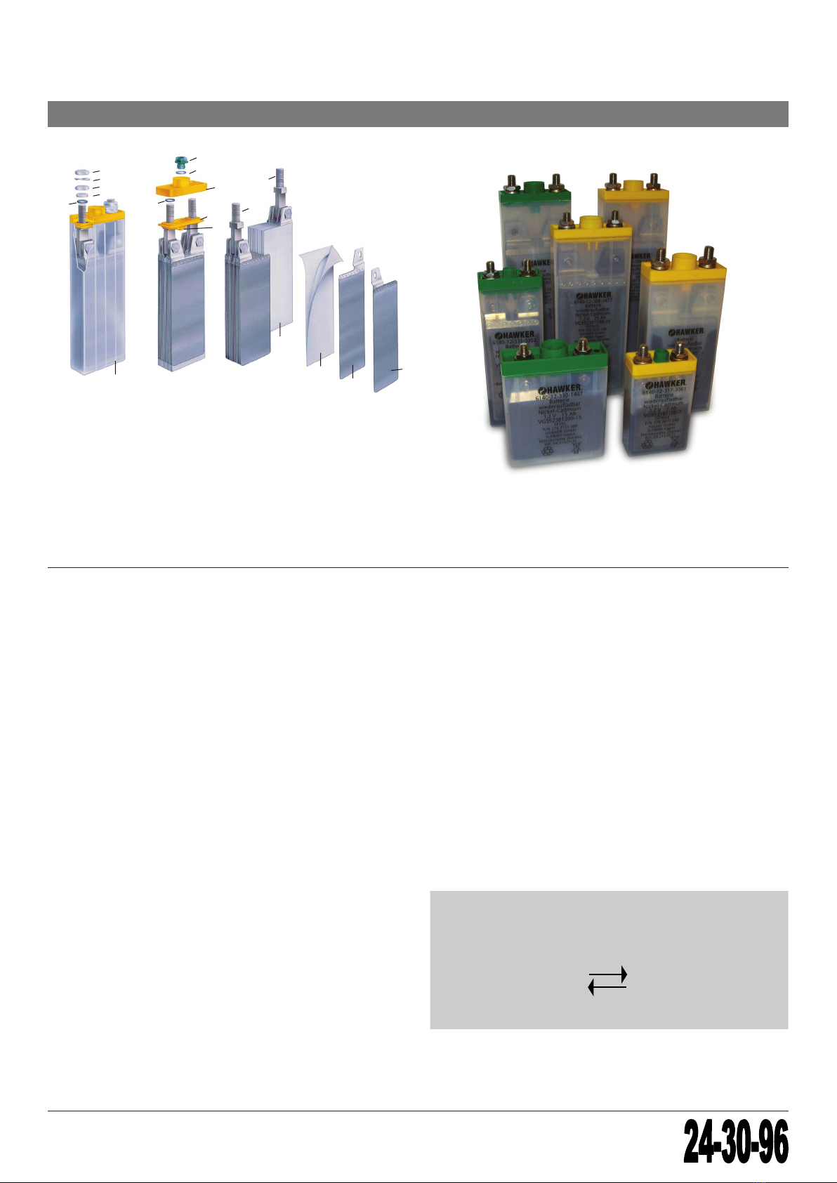
battery
1.2.1. THE BATTERY
The 24V battery is made up of 20 cells connected in series,
which are assembled in a battery case. The battery
container and the lid are typically made of stainless steel.
Some battery types have a container of stainless steel and
a lid of polymer material. The interior container walls are
lined with heat resistant plastic plates. The lid is lined with
a ribbing, which acts as a pressure pad for the cells. The
electrical connector typically is mounted on the front of the
battery container; but on some battery types the electrical
connector is mounted at the side. It enables electrical
connection of the battery to the power supply system. All
batteries can be additionally fitted with heater and
temperature sensors or temperature sensors only.
6
1. M inten nce M nu l for the HAWKER®Ni/Cd
Airborne B ttery – Purpose nd Use
Figure one: Batteries
The manual describes the processes
for trained technicians to maintain
Hawker®nickel-cadmium airborne
batteries. It informs about their basic
design features and details structured
tasks for visual inspection, diagnostic,
testing, performance reconditioning,
repair and the necessary care to
maintain best endurance and useful
life of these batteries.
Trained staff only should have access
to the manual, which always shall be
of latest revision and kept in good
condition by the battery owner.
Number of cells
Number of cells
Battery Capacity
Battery with thermostats
Number of thermostats
Special designed batteries
Cells designed for high rate applications
20
20
25 H1C (BER)1T
FP
F
Type of electrodes
Type of electrodes
Elements of the Battery designation:
The Hawker®aircraft battery designations
consist of the following elements
The document reference is online, please check the correspondence between the online documentation and the printed version.
1.2.2 THE CELLS
7
17
18
4
3
6
5
7
8
9
10
11
12
2
1
13
14
15
16
1 negative electrode 10 lid
2 positive electrode 11 seal (vent)
3 separator 12 vent (plug)
4 plate stack 13 upper terminal nut
5 negative pole terminal 14 springwasher
6 positive pole terminal 15 lower terminal nut
7 electrolyte level indicator 16 sealing cap
8 spacer 17 seal
9 seal 18 cell case
The cell comprises an assembly of positive (2) and
negative (1) sintered electrodes, alternately arranged and
meander-like separated with very thin hydrophilic layers of
polymer materials (3). The plate stack (4) with the two pole
terminals (5, 6) is placed in a prismatic plastic container
(18) which is leak-proof welded with a cell lid (10) that has
two bores for the poles and a centric threaded hole for the
vent (12). The vent closes the cell house filled with alkaline
electrolyte.
1.2.2.1. ositive and negative electrodes
The positive and negative electrodes are made of a
sintered metallic structure containing electrochemically
active masses in its pores. The metallic tabs welded to the
electrodes are acting as current collectors.
1.2.2.2 Separators
Three layers of oxidations-resistant separator made of
non-degradable synthetic materials separate the positive
and negative electrodes, arranged alternately. The outer
layers are of nonwoven fabric, whereas the inner layer is
a very thin hydrophilic polymer film. The film acts as
a gas barrier that is reducing the exothermic oxygen
recombination during charge and thus ensures excellent
charge stability of the cells.
1.2.2.3 Electrolyte
The electrolyte is a solution of potassium hydroxide in
deionised water with a typical density of 1.28 ± 0.02 kg/l
at 20°C.
Figure two: The cell
1.2.2.4 Vent plugs
The cell vents release the gas generated during float
charge, whilst also preventing electrolyte leakage and
contamination of electrolyte.
1.2.2.5 ole terminals, connectors and terminal nuts
Pole terminals, nuts and connectors used for the inter-cell
connection are made of highly conductive nickel-plated
copper material.
1.3 Basic electrochemical reactions in
cells
Positive Electrode = Nickel hydroxide – electrode
Negative Electrode = Cadmium/Cadmiumhydroxide –
electrode
Due to the very small changes in density by charge and
discharge operation, the density of the electrolyte cannot
indicate cell’s state of charge.
POSITIVE
ELECTRODE
NEGITIVE
ELECTRODE
POSITIVE
ELECTRODE
CHARGE
DISCHARGE
NEGITIVE
ELECTRODE
2Ni(OH)2Cd(OH)2
++
2NiO(OH) Cd+2H20
The document reference is online, please check the correspondence between the online documentation and the printed version.

1.3.1 CONVERSION O ENERGY
During charging, the active masses of the electrodes
convert electrical energy into chemical energy. The
discharge process reaction reverses it.
1.3.2 ELECTROLYSIS AND EVOLUTION O
GAS DURING OVERCHARGE AND
REVERSAL CHARGE
During overcharge, the water of the electrolyte is
decomposed. The hydrogen generated at the negative
Cadmium electrodes and oxygen generated at the positive
Nickelhydroxide electrodes escape through the vent of
the cell.
1.3.3
OXYGEN RECOMBINATION BY INTERNAL
ELECTROCHEMICAL REDUCTION ON
ELECTROLYTE-WET LIVE PARTS
A part of the oxygen generated, reduces according to the
two side reactions below. According to 1.3.2, the reduced
oxygen is equivalent to an amount of hydrogen that is not
generated. In total, the recombination of oxygen
suppresses the decomposition of water, but it heats
the cells.
Chemical reduction of oxygen at electrolyte-wetted
Cadmium during normal overcharge.
1.4 Specified definitions
1.4.1 CURRENT RATES
The current rates express values of current in ampere (A)
used to charge and discharge cells and batteries as a
multiple of its (nominal) current. or example, a current of
20 A used to charge a cell with a rated capacity of 100 Ah
would be expressed as C5= 0.2*I1or 0.2 C1= 0.2*I1.
1.4.2 RATED CURRENT (I1)
The rated discharge current of the battery returns not
less than its rated C1capacity in 1 hour.
8
2 H20 +
2H2 02
+++
4 0H° Heat
O
2
2 H
2
0
4e°
+++
2 Cd (OH)
2
Heat
2 Cd
0
2
2 H
2
0
1.4.3 RATED CAPACITY C1
The rated capacity is the minimum capacity, expressed in
Ah, obtained from a charged battery when discharged at
the I1rate to the EPV.
1.4.4 CONSTANT VOLTAGE CURRENT IPR
The Ipr is the discharge current, which the battery delivers
at the conclusion of a 15sec power discharge, controlled
as maintained a constant voltage of half the nominal
battery voltage.
1.4.5 EPV = END POINT VOLTAGE O
THE BATTERY
Unless otherwise stated during discharge the EPV of the
battery corresponds roughly to 1 Volt * number of cells.
1.5 Commonly used terms
1.5.1 CONSTANT (LOW) CURRENT
CHARGING (APPENDIX 2)
The constant current charging is a method used to charge
a fully discharged battery with a predefined current and
duration. The recommended rates for charge are 0.2*I1for
7 hours, or 0.1*I1for 14 hours. or the commissioning and
reconditioning of cells 8 hours at 0.2*I1is strongly
recommended.
1.5.2 IUI CHARGING – ( AST CHARGING IN
ACCORDANCE WITH APPENDIX 1)
The IUI-charge recommended in this manual is a general
method for recharging the batteries from an unknown
state of charge. It shall not be applied at battery
temperatures below 0°C and on batteries stored inactive
for more than 3 month.
1.5.3 END O CHARGE VOLTAGE
The end of charge voltage is the voltage of a battery or
cell prior to the charge current being switched off.
1.5.4 CONSTANT VOLTAGE CHARGING
Constant voltage charges (e.g. at 1.425 Volt per cell) shall
not be used to maintain and recondition the cells of
batteries as the overcharge at constant current (section
1.5.1) is more efficient to condition cells imbalanced from
cyclic services with constant voltage charges and shallow
discharges.
1.5.5 CAPACITY TEST
A capacity test is the measurement of the discharge time
and the discharge voltage at a constant discharge current
until the defined EPV is met. The product of discharge time
and discharge current calculates the capacity.
The document reference is online, please check the correspondence between the online documentation and the printed version.

1.5.6 OPEN CIRCUIT VOLTAGE
The open circuit voltage is the voltage of the battery,
without being connected to any units that can provide or
consume electrical power.
1.5.7 DEEP DISCHARGE
The deep discharge is a part of the maintenance process
“Reconditioning” to recover reversible losses of battery
capacity and discharge voltages, which might have been
created in service.
1.5.8 RECONDITIONING
Reconditioning is a process to recover reversible capacity
losses on cells imbalanced during shallow cycling and
discharge voltage reduction by continuous float charge, or
storage.
1.5.9 CAPACITY REDUCTION WHILE THE
BATTERY IS IN SERVICE
The battery capacity can reduce, if the on board charging
voltage is too low. This capacity reduction can be reversed
by battery maintenance.
9
1.5.10 AGEING AND LOSS O PER ORMANCE
Ageing causes battery’s irreversible losses of energy
conversion. These losses cannot be cured by electrical
treatments. One effect of cell’s ageing is the accumulation
of impurities, and of corrosion products in the electrolyte
and the electrodes of the cells. Any removal of such
effects, by undefined measures is inadmissible.
1.5.11 AIRWORTHINESS
Airworthiness is the compliance of battery component(s)
with all conditions and regulations required by the
approving authorities for their safe operation and
performance.
1.5.12 END O LI E CAPACITY.
The end of life capacity of maintained cells is defined as
≤80% of the rated capacity (compare section 1.4.3)
1.6 Technical data
1.6.1 OPERATIONAL PARAMETERS
• Operational temperature range limited from -50°C to 71°C;
• Continuous voltage controlled charges procedures should not be performed above 60°C (battery
temperature)
• Due to potential risk of any ice formation in the electrolyte of the cells should not be charged below -30°C
(battery electrolyte temperature)
• or any specific technical data refer to the relevant DDP (Declaration of Design and Performance) or Technical
Specification which can be requested from the authorised Hawker®representative.
1.6.2 TECHNICAL CELL DATA, TABLE 1
Cell designation FP44H1C FP40H1C FP38H1C FP27H1C FP25H1C FP22H1C FP17H1C FP7H1C FP4H1C
Rated voltage. (V) 1.2 1.2 1.2 1.2 1.2 1.2 1.2 1.2 1.2
Electrolyte – density Potassium hydroxide solution, density at 20°C: 1.28 kg/l ± 0.02 kg/l
Thread of upper pole nut M10 M10 M10 M10 M8 M8 M8 M8 M4
Torque of: lower pole nut
Torque of upper pole nut
7 Nm (70 kpcm)
10 Nm (100 kpcm)
4 Nm (40 kpcm)
5 Nm (50 kpcm)
0.9 Nm (9 kpcm)
1.6 Nm (16 kpcm)
Venting pressure Green vents 0.35 ± 0.2 bar;
Venting pressure Blue vents: 0.4 to 0.7 bar
The document reference is online, please check the correspondence between the online documentation and the printed version.

Battery
type
Type
No.
SAP
No*
Cell
type
Nominal
voltage (V)
Rated
capacity (Ah)
pr(A)
to 25°C
Length
(mm)
Width
(mm)
Height
(mm)
Typ. Weight
kg)
F20/4H1C-R 3349004 910 2314772 FP4H1C 24 4 150 166 118 109 4.5
F20/7H1C-E2 3349007 9000 2314845 FP07H1C 24 7 450 325 180 130 13.0
F20/15H1C 3349015 910 2314918 FP15H1C 24 15 600 198 195 196 16,7
F20/17H1C 3349017 910 2315047 FP17H1C 24 17 700 198 195 196 16.9
F20/17H1CT 3349017 960 2315096 24 17 700 198 195 196 17.1
F20/17H1C-1 3349017 920 2315055 24 17 700 253 158 188 16.9
F20/17H1CT2-1 3349017 900 2315039 24 17 700 253 158 188 17.2
F20/17H1C-2 3349017 930 2315063 24 17 700 260 147 188 17.0
F20/17H1CT-2 3349017 950 2315088 24 17 700 260 147 188 17.1
F20/17H1C-3 3349017 940 2315071 24 17 700 321 125 200 17.3
F20/22H1C-1 3349022 900 2315144 FP22H1C 24 22 900 424 119 180 23.5
F20/25H1C 3349025 900 2315274 FP25H1C 24 25 1025 254 197 223.5 25.5
F20/25H1CT 3349025 910 2315322 24 25 1025 254 197 223.5 25.6
F20/25H1C-L39 3349025 990 2315444 24 25 1025 402 207 250 28.5
F20/25H1CT2 3349025 920 2315355 24 25 1025 254 197 223.5 25.7
20FP25H1C-R 3349025 940 2315371 24 25 1025 363 174 226 24.5
20FP25H1CT-R 3349025 950 2315396 24 25 1025 363 174 226 24.5
F20/27H1C 3349027 920 2315622 FP27H1C 24 27 1125 254 248 204 27.5
F20/27H1CT 3349027 910 2315599 24 27 1125 254 248 204 27.6
F20/27H1C-T2 3349027 940 2315647 24 27 1125 254 248 204 27.7
F20/27H1C-E1 3349027 900 2315582 24 27 1125 363 168.5 218 28
F20/27H1C-M1 3349027 9600 2315703 24 27 1125 478.5 168.5 237.5 28.6
F20/27H1C-M1T 3349027 7000 2315509 24 27 1125 478.5 168.5 237.5 28.7
F20/27H1C-M3 3349027 8000 2315574 24 27 1125 478.5 168 218.5 29.4
20-FP38H1C-R 3349038 900 2315752 FP38H1C 24 38 1350 495 174 226 34.9
20FP38H1CT-R 3349038 901 2315769 24 38 1350 495 174 226 35.0
20FP38H1CT-R 3349038 9011 2315785 24 38 1350 495 174 226 35.0
20FP38H1CT2-R 3349038 9010 2315777 24 38 1350 495 174 226 35.1
F11/40H1C 3349040 100 2315793 FP40H1C 13.2 40 1500 223.5 182.5 253.5 21.7
F20/40H1C 3349040 910 2315914 FP40H1C 24 40 1500 254 248 262 36.4
F20/40H1CT 3349040 9206 2316002 24 40 1500 254 248 262 36.5
F20/40H1CT2(P) 3349040 9201 2315955 24 40 1500 254 248 262 36,6
F20/40H1C-AC 3349040 960 2316092 24 40 1500 254 248 262 36.5
F20/40H1C-E1 3349040 900 2315882 24 40 1500 363 168.5 268 38.5
F20/40H1CT/A 3349040 9200 2315947 24 40 1500 254 248 262 37.6
F20/40H1CT3 3349040 9209 2316035 24 40 1500 254 248 262 36.7
F20/44H1C 3349045 910 2316181 FP44H1C 24 44 1500 254 248 262 37,4
F20/44H1CT 3349045 920 2316198 24 44 1550 254 248 262 37.5
10
1.6.3 TECHNICAL BATTERY DATA: TABLE 2
The document reference is online, please check the correspondence between the online documentation and the printed version.

2.1 Safety Instructions, Warnings
and Notes
“CAUTION” is necessary, if non-adherence or
incorrect adherence to the service or working
instructions could cause injuries or fatal
accidents.
“ATTENTION” applies, if non-adherence or
incorrect adherence to the service or working
instructions might cause damage to the unit and
potential safety issues.
“NOTE” draws attention to important points.
2.2 General safety instructions:
• Observe the (local) instructions for battery
use and position them visibly near the
battery
• Trained personnel must only carry out
work on batteries
• Read the Material Safety data sheet.
• Use protective glasses and wear safety
clothing when working on batteries
• Adhere to the current accident prevention
rules in the country where the battery is
used.
• No smoking
• Do not expose batteries to naked flames,
glowing embers or sparks, as it may
cause the battery to explode. Avoid
sparks from cables or electrical apparatus
as well as electrostatic discharges.
• Avoid any contact of electrolyte with the
eyes, open wounds / skin and clothing
• Avoid ingestion of electrolyte. In case of
skin contact with electrolyte and/ or
ingestion of electrolyte as well as burns
consult a doctor immediately or “ irst
Aid”, flush skin and eyes with plenty of
water or a solution of boric acid in water,
11
2. S fety me sures nd instructions
• Remove electrolyte contaminated
clothes, immediately wash in excess of
acetic water
• The potassium hydroxide electrolyte
solution is highly corrosive.
• Avoid any spilling of electrolyte
• Do not disassemble cells since cadmium
and cadmium oxide is poisonous and is
believed to be carcinogenic. Nickel can
cause serious skin allergic reactions and
skin irritations to nickel sensitive and
exposed persons.
• Batteries are heavy.
• Use suitable transportation / lifting
equipment
• Battery vent tubes are not intended for
use as lifting handles.
• Risks of explosion and fire
• Do not use any inflammable organic
solvents, CHC’s and mixtures of it for
cleaning
• Do not dismantle cells
• Avoid conditions for electrical shocks by
using insulated tooling. Electrical short
circuits and sparks may injure the
operator, damage the battery and ignite
gases from charging
• Do not wear clothes with static fibres and
metallic accessories (rings, watches, belts
jewellery) when working on batteries. Use
a plastic brush and antistatic cleaning
cloth for dry wiping off adhesive dirt from
the battery
• Never place any conductive parts on
metallic parts of the battery
• Do not block the battery outlet pipes with
the liners
• Remove battery lid from container prior to
charging.
• Pay attention to the hazards that can be
caused by batteries.
The document reference is online, please check the correspondence between the online documentation and the printed version.

3.1 Log book
The operator shall record and confirm by signature in the log book the process steps and data measured on
the battery and its cells. These records are required to provide evidence of the airworthiness of the battery.
ailures to comply with this instruction may invalidate the warranty conditions.
3.2 Goods inwards inspection Task for new batteries
12
3. Commissioning of new b tteries
Task 3.1 – Goods inwards inspection of a new battery on receipt
OPERAT NG NSTRUCT ON AND TECHN CAL REQU REMENTS (TR) NSTRUCT ONS / EV DENCE WHEN DEV AT ONS FROM TR
1.
Visually check the delivered packing boxes with batteries for signs
of transportation and thermal damage as well as for moisture.
2. Unpack the boxes and check the delivery is
complete according to the accompanied documentation.
Contact the supplier.
3. Visually inspect the battery internally and externally
for signs of impact damage, corrosion and leakage.
Record the findings into the log book
Any defects quarantine the battery and contact the supplier.
4. For any additional goods inwards inspection refer
to the local regulations.
Record the findings into the log book.
5. Record the results in the battery log book.
The document reference is online, please check the correspondence between the online documentation and the printed version.

13
3.3 Commissioning Task 3.2 for new batteries
Task 3.2 – Commissioning of new batteries
OPERAT NG NSTRUCT ON AND TECHN CAL REQU REMENTS (TR) NSTRUCT ONS / EV DENCE WHEN DEV AT ONS FROM TR
ATTENTION
Never charge, discharge or adjust electrolyte on cells connected in
series outside the battery case.
1. Remove the lid from the battery case.
2.
Remove the caps from the main connector pins using insulated tools
Contact the supplier
3. Tighten the upper pole nuts with the correct torque as indicated in
Table 1 of section 1.6.2
Record the findings into the log book.
Any defects quarantine the battery and contact the supplier.
4. Measure the insulation resistance with a MΩ-meter at 250 V DC
between the + pin of the battery connector and the battery case
and the insulation resistances with same device at 250 V DC
between the + terminal of each cell and the battery case.
f R ≤ 10 MΩ due to moisture, remove the lid and store the
battery for 24 hours in an air-conditioned room and repeat the
test.
n case of failure: return the new battery to the supplier.
5. Undo the vents and keep them aside on the cells mouth.
ATTENTION
Do not top up the discharged cells at this stage
ATTENTION:
• Do not use mercury thermometer.
• Place none-insulated thermocouple probes between the cells.
6. nstall a thermometer or suitable insulated temperature probe in a
cell placed at the centre of the battery. The device shall touch the
separators of the plate stack.
7. Connect the battery to the charge / discharge unit.
8. Charge the battery for 8 hours at 0.2 1as shown in Appendix 2
(commissioning charge).
f necessary, adjust the electrolyte level of the cells
15 to 10 minutes prior to the end of charge.
Figure 3: adjusting electrolyte level
CA TION
Always wear protective goggles
and gloves when working on the
battery
ATTENTION
For adjusting the electrolyte level
use distilled water
The document reference is online, please check the correspondence between the online documentation and the printed version.

14
Figure 4: Electrolyte level indicator
ATTENTION
The electrolyte level of charged cells decreases after charge while
the gas is escaping. Do not adjust electrolyte level further.
9. Stand the battery for one hour on open circuit.
10. Check the battery temperature is below 35°C
11.
Ensure that the battery is connected to the charge/discharge unit.
12. Discharge the 24V Battery at
1
to 20 V.
Requirement: The voltage of each cell after 60 minutes must be equal
or greater than 1.0 V.
Note: f the discharge at the
1
rate is not feasible, select a different
set of discharge rate and criteria from the table below.
Record the cell voltages (column 3) in the log book.
f any battery does not meet the requirement contact
the supplier.
13. Soak the battery to room temperature for up to 8 hours before
recharging.
ATTENTION
f necessary, adjust the
electrolyte level to the
height that touches the
edge of the spacer.
Discharge current rate Time (min) cell voltage
reading
Voltage requirement for
cells (V)
0.2* 1300 ≥1.0
0.4* 1150 ≥1.0
0.6* 1100 ≥1.0
0.8* 175 ≥1.0
160 ≥1.0
The document reference is online, please check the correspondence between the online documentation and the printed version.

15
14.
Recharge the battery using a method indicated in section 14.1 or 14.2
or 14.3
• Adjust the electrolyte level at a current of 0.2* 115 minutes to 10
minutes prior to end of the charge methods, 14.1, 14.2, and 14.3
• Afterwards measure the voltage on each cell prior to the end of
charge at 0.2* 1
.
Requirement: cell voltage shall be ≥ 1.56 V
• Record the values in the log book.
Note:
f the battery has to be charged below 0°C, apply 7 hours charge
at 0.2* 1
.
ATTENTION:
• Do not charge the battery with currents higher than I1
• If you cannot fully supervise, do not use method described
in 14.3.
14.1 IUI charge – method (Appendix 1)
• Charge the battery at 1until voltage has increased to 1.55V times
number of cells and charge for 2 hours at 0.2* 1
• After about 1 hour charge, check that battery has reached the
voltage level to switch the charge current to 0.2* 1.
14.2 I charge method (Appendix 2)
• Charge the fully discharged battery for seven hours at 0.2* 1.
14.3 II charge method (Appendix 3)
ATTENTION:
• Charge the fully discharged battery with parameters selected
from the table below and afterwards charge for two hours at
0.2*I1
• Check battery current switching to 0.2*I1at the stage 1(max) time
presented in the table below.
n case cells fail this requirement, contact the supplier
15. Stand the battery for 1 hour minimum and 24 hour maximum and
then refit the vents on the cells and fit the lid in its correct
orientation as indicated by the arrowhead which points in the
direction of the main connector.
current Stage 1 time (max)
0.4* 1180
0.6* 1120
0.8* 190
The document reference is online, please check the correspondence between the online documentation and the printed version.

16
Task 3.3 – Specific release requirements
OPERAT NG NSTRUCT ON AND TECHN CAL REQU REMENTS (TR) NSTRUCT ONS / EV DENCE WHEN DEV AT ONS FROM TR
1. nstall the battery into the aircraft as described in the flight
manual.
NOTE
This manual does not provide aircraft-specific working instructions.
2. Carry out the pre-flight testing on ground as defined in the flight
manual, if required.
f the battery fails, reject it from service and send it to workshop
for maintenance.
3. Recharge the battery in the battery workshop, if more than
20% is discharged during the pre-flight tests as described in
the flight manual.
f charging is not described in the flight manual, remove the lid and
refresh charge battery for 7h at 1.425V per cell, with closed cell
vents.
3.4 Release to aircraft Task 3.3:
or any additional specific release requirement refer to Task 3.3 below
The document reference is online, please check the correspondence between the online documentation and the printed version.

4.2 Scheduled maintenance
procedures
4.2.1 MONTHLY CHECKS ON AIRCRA T.
If a monthly check is specified in the flight manual, then
carry out Monthly on "aircraft" check in accordance with
Task 7.1.
4.2.2 QUARTERLY MAINTENANCE
Quarterly maintenance shall be carried out 3 months after
installing the maintained battery into the aircraft. Tasks to
be undertaken are listed below and shall be carried out in
accordance with
Quarterly maintenance Task 7.2
Release-Inspection check Task 3.3.
17
4.1 Unscheduled maintenance
procedures
ollowing an unscheduled removal from aircraft the battery
shall be taken to the battery workshop for investigation in
accordance with the following steps.
• ault inding: refer to Section 9
• Inspection and Diagnostic: Task 10.1
• Repair: (repair the battery as necessary in accordance
with Tasks below:).
Task 10.2 – replacement of upper pole nuts, spring
washers and intercell links
Task 10.3 – replacement of lower pole nuts, sealing
caps and seals
Task 10.4 – replacement of the thermostat switch
assembly
Task 10.5 – replacement of the main battery
connector
Task 10.6 – replacement of the battery case and or
battery lid
Task 10.7 – replacement of the cell(s)
Task 10.8 – replacement of the insulating materials
Task 10.9 - Commissioning of repaired battery:
4. M inten nce Interv ls
4.2.3 ANNUAL MAINTENANCE
Annual maintenance overhaul shall be carried out
every 12 months.
Tasks to be undertaken are listed below and shall be
carried out in the presented sequence.
Annual maintenance Task 7.3
Release-Inspection check Task 3.3.
4.3 Maintenance Facility.
The maintenance on Hawker®batteries shall be
carried out in a dedicated battery shop by trained
technicians. Requirements for battery maintenance
shops are defined in specifications.
4.4 Spare parts for repair
Any battery components used for replacing defective
parts at repair shall comply with part number as
identified in the battery-specific IPL. Only Hawker®
approved spare parts shall be used.
4.5 Equipment, Tools and
Consumables for maintenance
Hawker®recommends the use of equipment, tools
(listed in Appendix 5) and consumable (listed in
Appendix 6) for maintenance and repair on Hawker®
batteries.
The document reference is online, please check the correspondence between the online documentation and the printed version.

5.1 Short-term storage of charged
batteries
Maintained and charged batteries can be stored for 3
months at ≤35°C in a secured area.
Refer to Task 5.1 - Storage of maintained (overhauled)
charged batteries up to 3 month.
The batteries shall be stored:
• without being trickled charged
• in upright position
• with vents tightened
• with the lid locked on the battery case,
• plastic caps are mounted on both pins of the
connector
• in a well-ventilated or air-conditioned room
between 10°C and 35°C and a relative humidity
between 45 and 75%
• protected from dust, moisture, corrosive gases
and excessive heat
• in an area with authorised access, only.
Prior to installing the battery on the aircraft, it shall be
recharged for 7 hours with a constant voltage of 1.425
V per cell.
After 3 months storage the battery shall be subjected
to quarterly maintenance.
18
5.0 Stor ge T sks for irworthy b tteries
5.2 Long-term storage (up-to 5 years) of
discharged batteries
Batteries can be stored between 3 months and 5 years
only in a discharged state.
Refer to Task 5.2 for long-term storage preparation
procedures.
The batteries shall be stored:
• Always in maintained and discharged condition
• in upright position
• with vents tightened
• with the lid locked on the battery case
• plastic caps are mounted on both pins of the
connector
• in a well-ventilated or air-conditioned room
between 10°C and 35°C and a relative humidity
between 45 and 75%
• protected from dust, moisture, corrosive gases
and excessive heat
• in an area with authorised access, only.
W
hen returning the battery back into service, carry out Task
5.3 “Commissioning of prolonged stored batteries”.
Task 5.1 – Storage of maintained (overhauled) charged batteries up to 3 month
OPERAT NG NSTRUCT ON AND TECHN CAL REQU REMENTS (TR) NSTRUCT ONS / EV DENCE WHEN DEV AT ONS FROM TR
1. Carry out the scheduled maintenance procedure on the battery,
either Task 7.2 or Task 7.3.
2. Store the battery in a ventilated room at temperatures
recommended 10°C and 35°C and at relative humidity between
45% and 75%.
3. f returning the battery to service within the 3 months storage time,
recharge with a constant voltage of 1.425 V per cell at 20°C ± 5°C
without opening the vents.
f the charged battery is stored for longer than 3 months and shall
be returned to service, subject it to quarterly maintenance
procedure Task 7.2.
4. f required, release the battery to service according to Task 3.3.
The document reference is online, please check the correspondence between the online documentation and the printed version.

19
Task 5.2 - reparation for long term storage
OPERAT NG NSTRUCT ON AND TECHN CAL REQU REMENTS (TR) NSTRUCT ONS / EV DENCE WHEN DEV AT ONS FROM TR
1. Carry out the scheduled maintenance procedure on the battery in
accordance with Task 7.3.
2. Discharge the battery to an average of 1V per cell using current
rates between 1and 0.1* 1.
3. Store the battery in a well-ventilated or air-conditioned room at
temperatures between 10°C and 35 °C and at relative humidity
between 45% and 75% up-to a maximum of 5 years.
Task 5.3 – Commissioning of prolonged stored batteries
OPERAT NG NSTRUCT ON AND TECHN CAL REQU REMENTS (TR) NSTRUCT ONS / EV DENCE WHEN DEV AT ONS FROM TR
1. Remove the lid from the battery case.
2. Remove the caps from the main connector pins using
insulated tools.
ATTENTION:
• Do not top up the discharged cells at this stage
• ndo the vents and keep them aside on the cells mouth.
ATTENTION:
• Do not use mercury thermometer
• Place none-insulated thermocouple probes between the cells.
3. nstall a thermometer or suitable insulated temperature probe
in a cell placed at the centre of the battery. nstall non-insulated
temperature probe between the cells.
4. Connect the battery to the charge / discharge unit.
5. Charge the battery for 8 hours at 0.2* 1as shown in
Appendix 3 (commissioning charge).
f necessary, adjust the electrolyte level of the cells prior to
the end of charge.
Figure 3: adjusting electrolyte level
CA TION
Always wear protective goggles
and gloves when working on the
battery
ATTENTION
For adjusting the electrolyte
level use distilled water
The document reference is online, please check the correspondence between the online documentation and the printed version.

20
Figure 4: Electrolyte level indicator
ATTENTION
The electrolyte level of charged cells decreases after charge
while the gas is escaping. Do not adjust electrolyte level
further.
6. Stand the battery for one hour.
7. Check the battery temperature is below 35°C. f battery temperature above, soak it to ambient
room temperature.
8. Ensure that the battery is connected to the charge/
discharge unit.
9. Discharge the 24V Battery at 1to 20 V.
Requirement: The voltage of each cell after 48 minutes must be
equal or greater than 1.0 V.
Note: f the discharge at the 1rate is not feasible, select a different
rate and criteria from the table below.
f any battery does not meet the requirement contact
the supplier.
10. Soak the battery to room temperature for up to 8 hours before
recharging.
ATTENTION
f necessary, adjust the
electrolyte level to the
height that touches the
edge of the spacer.
Discharge current rate Time (min) cell voltage
reading
Voltage requirement
for cells (V)
0.2* 1240 ≥1.0
0.4* 1120 ≥1.0
0.6* 180 ≥1.0
0.8* 160 ≥1.0
148 ≥1.0
Record the cell voltages (column 3) in the log book.
The document reference is online, please check the correspondence between the online documentation and the printed version.
This manual suits for next models
36
Table of contents
Other Hawker Camera Accessories manuals


