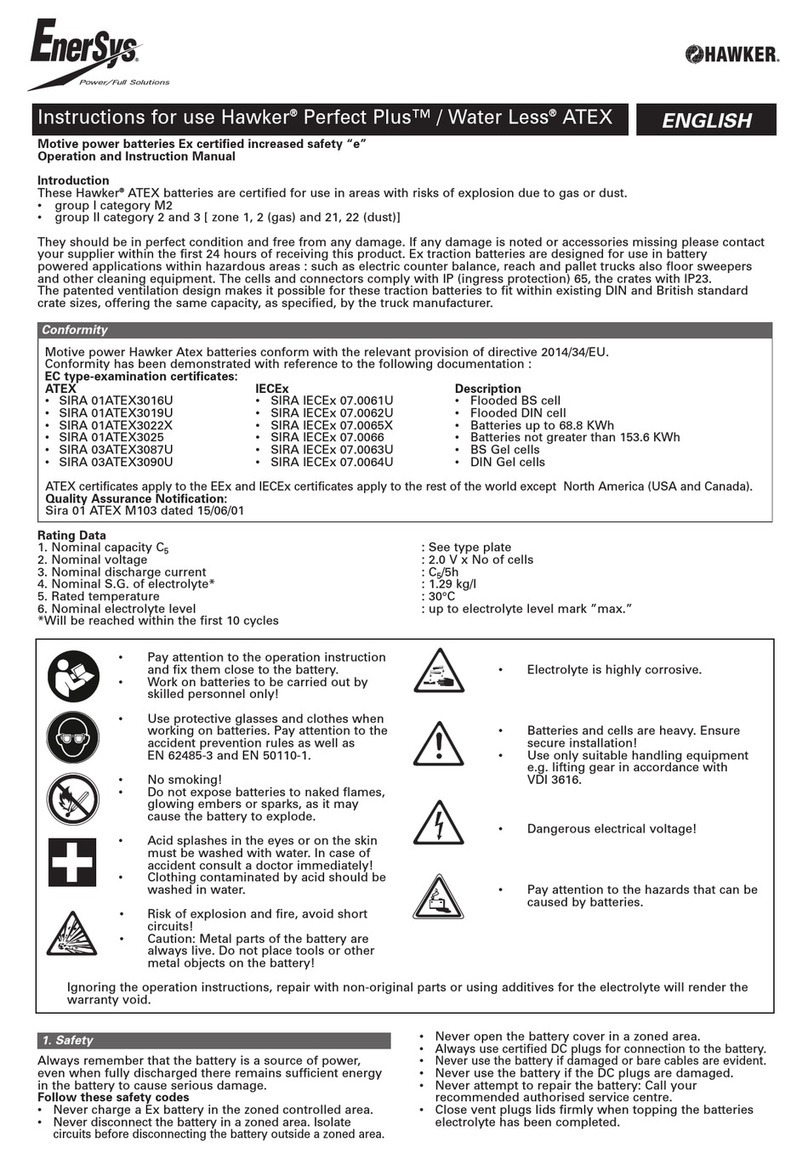
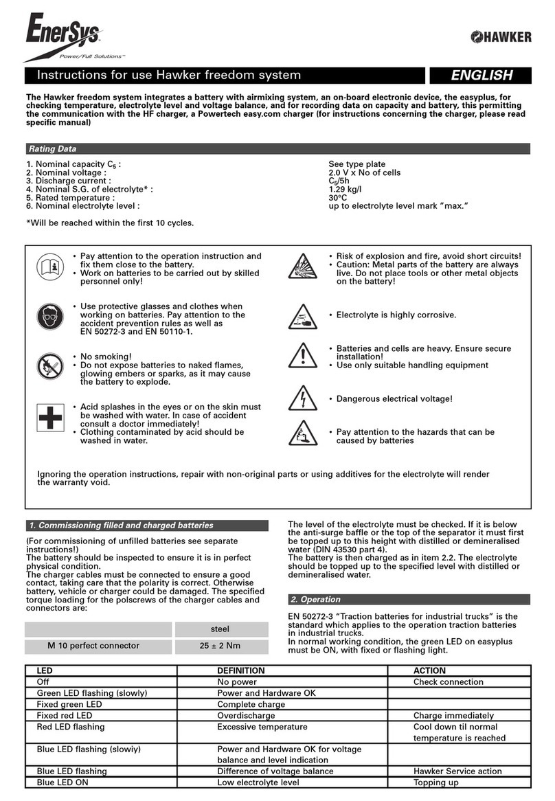
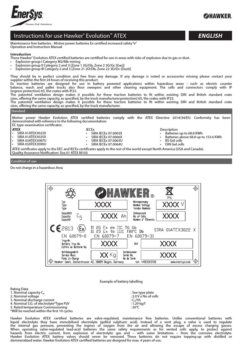
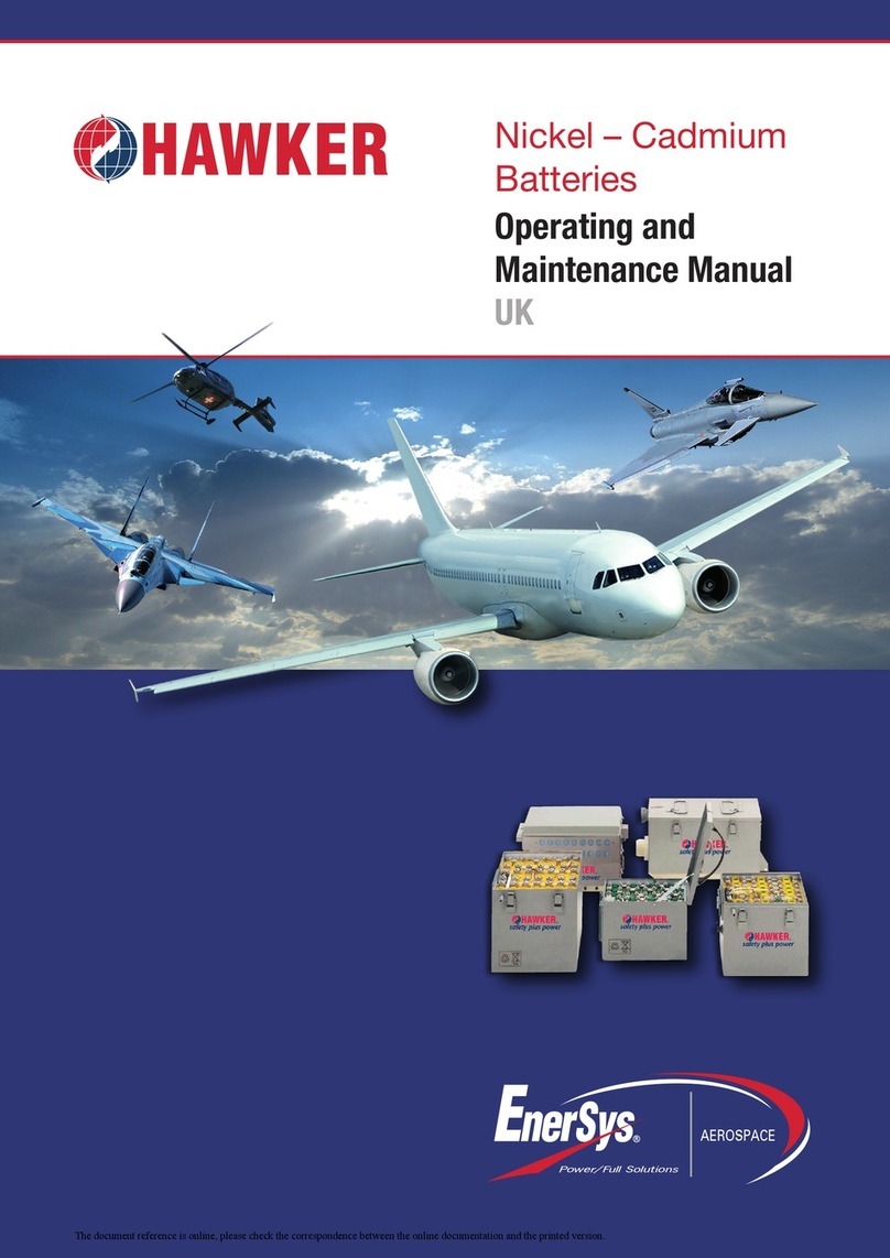
Hawker Evolution User manual

Instruction Manual
Sealed Gel Battery
Battery Part Number
Purchaser
Vehicle Model
Invoice / Spec Number
Date Supplied
Battery Serial Number
Despatch Voltage
Fleet / Serial Number

The awker Evolution®battery is equipped with
an easycontrol or Wi-IQ, an electronic device
fitted to the battery connectors. The presence
of this device is mandatory on each battery.
The battery, including all cables, links and plugs
should be inspected upon receipt to ensure it is
in perfect physical condition.
The battery should be in a fully charged
condition. If it requires charging ,see Item 2.2
Use special plug coding systems for the battery
to prevent accidental connection to a wrong
type of charger.
The charging cables must be connected to
ensure a good contact, taking care that the
polarity is correct, otherwise battery, vehicle or
charger could be damaged.
Pay attention to the operating instructions
and keep them close to the battery.
Work on batteries should be carried out by
a qualified technician!
Use protective glasses and clothes
when working on batteries. Pay attention
to the accident prevention rules as well as
AS/NZ1337, EN50272-3 & EN 501110-1
No smoking ! Do not expose batteries to
naked flames, glowing embers or sparks,
as it may cause the battery to explode.
Acid splashes in the eyes or on the skin
must be washed with plenty of fresh clean
water. In case of accident, consult a
doctor immediately !
Remove contaminated clothing
Risk of explosion and fire
Avoid short circuits!
Metal parts of a battery are always live.
Do not place tools or other metal objects
on the battery!
Electrolyte is highly corrosive.
Avoid contact with skin and eyes
Do not mix with alkaline solutions
In normal operation contact with acid is not
possible. If cell containers are damaged, the
gelled electrolyte is corrosive.
Do not remove the battery plugs
Batteries and cells are heavy.
Ensure secure installation
Use only suitable handling equipment
Lifting hooks must not damage the cells,
connectors or cables
Dangerous electrical voltage!
Pay attention to the environmental
hazards of batteries.
Please recycle
awker Evolution batteries are VRLA - valve regulated, maintenance free batteries.
Unlike conventional wet batteries they have immobilised electrolyte (gelled sulphuric acid).
Instead of a vent plug, a valve is used to regulate the internal gas pressure, preventing the ingress
of oxygen from the air and allowing the escape of excess charging gasses.
When operating valve-regulated lead-acid batteries the same safety requirements as for vented
cells apply, to protect against hazards from electric current, from explosion of electrolytic gas and
with some limitations, from the corrosive electrolyte.
The battery valves should never be removed. These batteries do not require topping-up with water.
Ignoring the operating instructions, repair with non-original parts, using a itives for the
electrolyte or isconnection of the easycontrol™or Wi-IQ®monitors will ren er the warranty
voi .
Nominal Capacity C
5
: See Battery plate
Nominal Voltage : See Battery plate (2.0V x No. of cells)
Discharge Current : C
5
/ 5h
Nominal S.G of Electrolyte* : 1.29 kg/l
Rated Temperature : 30ºC
Traction batteries with positive tubular plates type PzV / PzVB
* Will be reached within the first 10 cycles
1. Comm ss on ng Battery
Rat ng Data

The specified torque loading for the terminal
screws of the charging cables and connectors is
25Nm +/- 2Nm.
Never directly connect an electrical appliance
(for example: warning beacon) to some cells of
the battery. This could lead to a voltage
imbalance of the cells during the recharge
causing a loss of capacity, the risk of insufficient
discharge time and damage to the cells.
T IS MAY EFFECT T E WARRANTY
Standards AS2402.2.2-2005 & EN50272-3 apply
to the installation and usage of valve regulated
cell traction batteries in industrial trucks.
Ventilation openings must not be sealed or
covered.
Electrical connections (e.g. plugs) must only be
connected or disconnected in the open circuit
condition.
To optimise battery life, deep discharges of
more than 80% of nominal capacity must be
avoided.One cycle (80% C5) per 24 hour period.
To measure the depth of discharge (DOD) use
only recommended discharge indicators with an
energy cut-off at 80% (1.83 v.p.c loaded) for a
12 hour recharge, and 60% (1.87 v.p.c loaded)
for an 8 hour recharge time.
Both partially and fully discharged batteries must
be recharged immediately and not left in a
discharged condition.
Batteries can be used in normal duty cycle for a
maximum 6 days per week.
Avoid applications where:
• No allowance for battery to cool
• eavy Duty cycle leading to increase of
battery temperature during operation.
Only direct current must be used for charging.
Only connect to an Enersys approved charger
suitable for type and size of battery, to avoid
overloading of electric cables and contacts
unacceptable gassing and damage to the cells.
IUI profile: Nominal current 0.17 - 0.20 X C5
Voltage regulation 2.37v.p.c @ 30°C
Finish constant current C5/200 4rs
A full charge shall be carried out every working
day. The charging time for an 80% discharged
battery shall be 12 hours or 8 hours for a 60%
discharged battery. If the charger was not
purchased together with the battery, it is best to
have its suitability checked by Enersys. Any
changes or repairs to the battey or charger must
be performed by our service division.
Gel batteries have a low gas emission, however,
during charging, proper provision must be made
for venting of the charging gases complying to
AS2402.2.2-2005 & EN 50272-3.
Lids and covers of battery compartments must
be opened or removed and in the case of a
closed battery compartment, the battery must be
removed.
The vent plugs should stay on the cells and
never be removed.
With the charger switched off connect the
battery, ensuring that the polarity is correct.
(Positive to Positive, Negative to Negative).
Now switch on the charger.
The charger will indicate end of charge.
Do not interrupt the charge cycle.
Equalising charges are used to optimise the life
of the battery and to maintain its capacity.
4 hrs @ C5/200
With the correct charger, an equalisation charge
is automatically carried out weekly after the end
of the normal charge.
The temperature range of use for the battery is
between +5 °C and + 35 °C. Any use outside of
this range must be approved by Enersys.
Optimal battery life is obtained for a battery
temperature of 25 -30 °C. igh temperatures
reduce battery life according to IEC 1431
technical report, lower temperatures reduce the
capacity available.
2. Operat on
2.1 D scharg ng
2.2 Charg ng
2.3 Equal s ng Charge
2.4 Temperature

Charge the battery after every discharge.
Check that the plugs, links, cables and tray are
in good condition.
Visually inspect after recharge for signs of
mechanical damage and cleanliness of battery.
Ensure an equalising charge is carried out
(see 2.3).
Following the recharge, with the charger
switched on (C5/100), measure and record the
cell voltages and temperature using the pages
at the end of this document.
If there are significant changes from earlier
measurements or differences between the cells
are found, further testing and maintenance by
the service department should be requested.
Inspect & remove dust from within the charger.
Check that the plugs, links, cables and tray are
in good condition.
At least once per year the insulation resistance
of the battery must be checked in accordance
with EN 1175-1 & EN 1987 part 1.
The insulation resistance of the battery must not
be below a value of 50Ω per volt of nominal
voltage in compliance with EN 50272-3.
For batteries up to 20V nominal voltage, the
minimum is 1000Ω.
The electrolyte is immobilised in a gel.
The density of the electrolyte cannot be
measured.
• Never refill with water!
• Never remove the safety valve from the cell
In case of accidental damage of the valve,
contact our service department.
The battery should always be kept clean and
dry to prevent tracking currents.
Damage to the insulation of tray should be
rectified after cleaning, ensuring insulation value
is within limits (DW 0510 section 3) and to
prevent tray corrosion.
If it is necessary to remove cells, repair plugs or
cables contact our service department.
If batteries are taken out of service for a lengthy
period they should be stored in the fully charged
condition in a dry, frost-free room.
Storage is not allowed when in a dischared
state.
Batteries should be recharged after a maximum
storage time of 2 mths (30ºC), 3 mths (20ºC).
To ensure the battery is always ready for use a
choice of charging methods should be made -
• A monthly equalising charge as in point 2.3
• Float charging at 2.27v.p.c X number of cells.
The storage time should be taken into account
when considering the life of the battery.
If malfunctions are found on the battery or the
charger, our service department should be
called without delay.
The measurements taken in point 3.3 will
facilitate fault finding and their elimination.
A service contract will make it easier to detect
and correct faults promptly.
4. Care Of The Battery
5. Storage and Stabl ng
6.Malfunct ons
3. Ma ntenance
3.1 Da ly
3.2 Weekly
3.3 Monthly
3.4 Annually

The battery is fitted with an onboard battery monitoring device.This is mandatory.
There are two devices available - an easycontrol™ or a Wi-IQ®monitor.
These devices capture battery operating data for later reporting and analysis, whilst at the same
time offer visual warnings to the operator on the current status of the battery- refer table below.
The Wi-IQ has additional features and will therefore also measure current and Ah throughput.
The information is stored in memory and can be transferred to a computer via IR interface (easy) or
wirelessly (Wi-IQ). Propriety connection tools / software are required in both cases.
The Red and Green LED’s indicate the state and temperature of the battery.
The Blue LED’s indicate the level of electrolyte (wet cell only), voltage balance and communication
status
The easycontrol can enable charge profile adaptation and promote warnings to the awker
Powertech™ or Lifeplus®range of chargers, whilst the Wi-IQ will communicate to the LifeIQ™&
LifespeediQ™ range.
9. easycontrol™ & W -IQ®Data Mon tors
LED Definition Removal
1 Fixed Green Complete Charge Discharge Battery
Green Flashing Slowly Normal State Discharge Battery
2 Red Flashing Over Temperature Cool / Rest Battery
3 Fixed Red Over-discharged Recharge Battery
Note: Temperature LED has priority over others
4 Blue Flashing Battery voltage imbalance Rectify, reset via software
5 Fixed Blue Low electrolyte level(wet cell only) Water the battery
Note: Electrolyte warning disabled on Gel battery
Wi-IQ® device
easycontrol™ device

Maintenance Log
Month Year
Monthly Full Readings (After Equalising)
Cell No. Cell Volts Cell No. Cell Volts
1
2
3
4
5
6
7
8
9
10
11
12
13
14
15
16
17
18
19
20
21
22
23
24
25
26
27
28
29
30
31
32
33
34
35
36
37
38
39
40
Pilot Cell Temperature °C Battery Voltage V

Maintenance Log
Month Year
Monthly Full Readings (After Equalising)
Cell No. Cell Volts Cell No. Cell Volts
1
2
3
4
5
6
7
8
9
10
11
12
13
14
15
16
17
18
19
20
21
22
23
24
25
26
27
28
29
30
31
32
33
34
35
36
37
38
39
40
Pilot Cell Temperature °C Battery Voltage V

Maintenance Log
Month Year
Monthly Full Readings (After Equalising)
Cell No. Cell Volts Cell No. Cell Volts
1
2
3
4
5
6
7
8
9
10
11
12
13
14
15
16
17
18
19
20
21
22
23
24
25
26
27
28
29
30
31
32
33
34
35
36
37
38
39
40
Pilot Cell Temperature °C Battery Voltage V

Maintenance Log
Month Year
Monthly Full Readings (After Equalising)
Cell No. Cell Volts Cell No. Cell Volts
1
2
3
4
5
6
7
8
9
10
11
12
13
14
15
16
17
18
19
20
21
22
23
24
25
26
27
28
29
30
31
32
33
34
35
36
37
38
39
40
Pilot Cell Temperature °C Battery Voltage V

Maintenance Log
Month Year
Monthly Full Readings (After Equalising)
Cell No. Cell Volts Cell No. Cell Volts
1
2
3
4
5
6
7
8
9
10
11
12
13
14
15
16
17
18
19
20
21
22
23
24
25
26
27
28
29
30
31
32
33
34
35
36
37
38
39
40
Pilot Cell Temperature °C Battery Voltage V

Maintenance Log
Month Year
Monthly Full Readings (After Equalising)
Cell No. Cell Volts Cell No. Cell Volts
1
2
3
4
5
6
7
8
9
10
11
12
13
14
15
16
17
18
19
20
21
22
23
24
25
26
27
28
29
30
31
32
33
34
35
36
37
38
39
40
Pilot Cell Temperature °C Battery Voltage V

Maintenance Log
Month Year
Monthly Full Readings (After Equalising)
Cell No. Cell Volts Cell No. Cell Volts
1
2
3
4
5
6
7
8
9
10
11
12
13
14
15
16
17
18
19
20
21
22
23
24
25
26
27
28
29
30
31
32
33
34
35
36
37
38
39
40
Pilot Cell Temperature °C Battery Voltage V

Maintenance Log
Month Year
Monthly Full Readings (After Equalising)
Cell No. Cell Volts Cell No. Cell Volts
1
2
3
4
5
6
7
8
9
10
11
12
13
14
15
16
17
18
19
20
21
22
23
24
25
26
27
28
29
30
31
32
33
34
35
36
37
38
39
40
Pilot Cell Temperature °C Battery Voltage V

Maintenance Log
Month Year
Monthly Full Readings (After Equalising)
Cell No. Cell Volts Cell No. Cell Volts
1
2
3
4
5
6
7
8
9
10
11
12
13
14
15
16
17
18
19
20
21
22
23
24
25
26
27
28
29
30
31
32
33
34
35
36
37
38
39
40
Pilot Cell Temperature °C Battery Voltage V

Maintenance Log
Month Year
Monthly Full Readings (After Equalising)
Cell No. Cell Volts Cell No. Cell Volts
1
2
3
4
5
6
7
8
9
10
11
12
13
14
15
16
17
18
19
20
21
22
23
24
25
26
27
28
29
30
31
32
33
34
35
36
37
38
39
40
Pilot Cell Temperature °C Battery Voltage V

Maintenance Log
Month Year
Monthly Full Readings (After Equalising)
Cell No. Cell Volts Cell No. Cell Volts
1
2
3
4
5
6
7
8
9
10
11
12
13
14
15
16
17
18
19
20
21
22
23
24
25
26
27
28
29
30
31
32
33
34
35
36
37
38
39
40
Pilot Cell Temperature °C Battery Voltage V

Maintenance Log
Month Year
Monthly Full Readings (After Equalising)
Cell No. Cell Volts Cell No. Cell Volts
1
2
3
4
5
6
7
8
9
10
11
12
13
14
15
16
17
18
19
20
21
22
23
24
25
26
27
28
29
30
31
32
33
34
35
36
37
38
39
40
Pilot Cell Temperature °C Battery Voltage V

Maintenance Log
Month Year
Monthly Full Readings (After Equalising)
Cell No. Cell Volts Cell No. Cell Volts
1
2
3
4
5
6
7
8
9
10
11
12
13
14
15
16
17
18
19
20
21
22
23
24
25
26
27
28
29
30
31
32
33
34
35
36
37
38
39
40
Pilot Cell Temperature °C Battery Voltage V

Maintenance Log
Month Year
Monthly Full Readings (After Equalising)
Cell No. Cell Volts Cell No. Cell Volts
1
2
3
4
5
6
7
8
9
10
11
12
13
14
15
16
17
18
19
20
21
22
23
24
25
26
27
28
29
30
31
32
33
34
35
36
37
38
39
40
Pilot Cell Temperature °C Battery Voltage V

Back to the manufacturer!
Batteries with this sign must be recycled.
Batteries which are not returned for the recycling process must be disposed of as hazardous waste!
When using motive power batteries an chargers, the operator must comply with the
current stan ar s, laws, rules an regulations in force in the country of use!
Japan
5F Mitaka Mitsubishi Building
Shimorenjyaku 3-26-12
Mitaka, 181 0013, Tokyo
+81 422 70 3831
Asia Hea quarters
#11-03
Gateway East Building
152 Beach Road
Singapore, 189721
www.enersys-asia.com
Local Distributor / Contact: Singapore
No. 85 Tuas Ave 1
Singapore, 639518
+65 6558 7333
Publication: 32610D – Hawker Evolution Instruction Manual
Feb 2015. Sub ect to revisions without prior notice. E&OE
© Enersys. All rights reserved.
All trademarks and logos are the property of, or licensed to Enersys and its affiliates
China
Room 902,Sheng Gao Int. Building
No. 137 Xian Xia Road
Shanghai, PRC, 200131
+86 21 6273 6300
Australia / New Zealan
46 Egerton St
Silverwater, NSW, 2128
+61 2 9739 9999
In ia
Plot No: 1057M, 1st Floor
Road #45, Jubilee ills
yderabad, 500033
+91 40 670 46701
Malaysia
No.10 Jalan Anggerik Mokara 31/47
Kota Kemuning,Seksyen 31
40460 Shah Alam
Selangor Darul Ehsan, Malaysia
+60 3 5125 1111
Other Hawker Camera Accessories manuals
