manuals.online logo
Brands
  1. Home
  2. •
  3. Brands
  4. •
  5. Hawkeye Mfg
  6. •
  7. Tank Equipment
  8. •
  9. Hawkeye Mfg 5000 Series Technical Document

Hawkeye Mfg 5000 Series Technical Document

Series 5000 EPRV (8 - 12”) Installation, Operation and Maintenance Guide - Oct-2021 1
NOTE: INFORMATION REQUIRED FOR SUCCESSFUL
INSTALLATION
CAUTION: INFORMATION IF NOT FOLLOWED MAY
RESULT IN DAMAGE OR INSTALLATION FAILURE
WARNING: INFORMATION IF NOT FOLLOWED MAY
RESULT IN INJURY OR DEATH
PA R T A :
INSTALLING SERIES 5000 EPRV
TOOLS
»Pair of 3/4 Box and/or Socket Wrench for weight
attachment.
»Pair of box and/or socket wrench for flange bolting
(torque wrench preferred). See below for sizes:
WRENCH SIZES
CONNECTION SIZE REC. TORQUE†
8” API 3/4 14 FT-LB
10” ANSI 150# 1-5/16 48 FT-LB
12” ANSI 150# 68 FT-LB
†Values above based on achieving a 4-psi bubble tight
seal using full-face chloroprene gasket on smooth and
clean surfaces. Installing with fastener torques higher than
suggested may reduce long-term sealing performance,
and user does so at own risk.
PARTS REQUIRED
»1× Single arm Series 5000 EPRV (8, 10 or 12”)
»1× Base Gasket (*)
»1× Bolt Kit sized for connection (*)
* Match to EPRV connection size.
1 Place tank gasket and EPRV on the Flange and align
holes.
INSTALLATION, OPERATION AND MAINTENANCE GUIDE
SERIES 5000 EPRV (8  12”)
This document contains the recommended procedures for installing, operating and maintaining the Series 5000 EPRV in 8, 10, 12 Sizes. Read and understand this document prior to
installation, operation or maintenance of the EPRV.
2 Secure EPRV in place with bolts and nuts supplied
in the bolt kit. Use washers on the EPRV side of the
bolted connection. Install hand-tight, then torque to
recommended value using sequence shown in Section
C4.
3 Remove nut and top washer from weight hanger
bolt and set weights over weight hanger bolt. The set
pressure of the EPRV with no weights installed is 1 ozsi
and increases with the addition of weight plates.
4 Replace weight hanger nut and washer and tighten
to 68 ft-lb.
WEIGHT PART NUMBER REFERENCE
8 NPS 10 NPS 12 NPS
1.0 ozsi 220.310.040 225.310.051 225.312.051
2.0 ozsi 220.310.050 225.310.052 225.312.052
STANDARD INSTALLATION COMPLETE.
A2 (OPTIONAL) TRANSPORT LOCK
The transport lock can be installed on the 8” EPRV to
prevent damage to the device while the tank is being
transported in the vertical or horizontal position. The
transport lock holds the EPRV in a slightly open position.
This restricts entry of dust and contaminants into the
tank and prevents the internal pressure of the tank from
exceeding allowable limits during transport and if the
lock is accidentally left in place when the tank is placed in
service.
NOTE: THE TRANSPORT LOCK IS ONLY AVAILABLE ON
THE 8” API ERPV.
PARTS REQUIRED
»1× Installed 8” EPRV
»1× EPRV Transport Lock Kit
1 Remove the cotter pin, washers and clevis pin from the
transport lock kit.
2 Set the forked end of the transport lock arm over the
lock attachment point on the EPRV base and replace
the cotter pin, washer and clevis pin.
3 The transport lock can be left in the lowered position
until it is required. To prepare the EPRV for transport
proceed to section B1.
OPTION INSTALLATION COMPLETE.
Series 5000 EPRV (8 - 12”) Installation, Operation and Maintenance Guide - Oct-20212
PART B
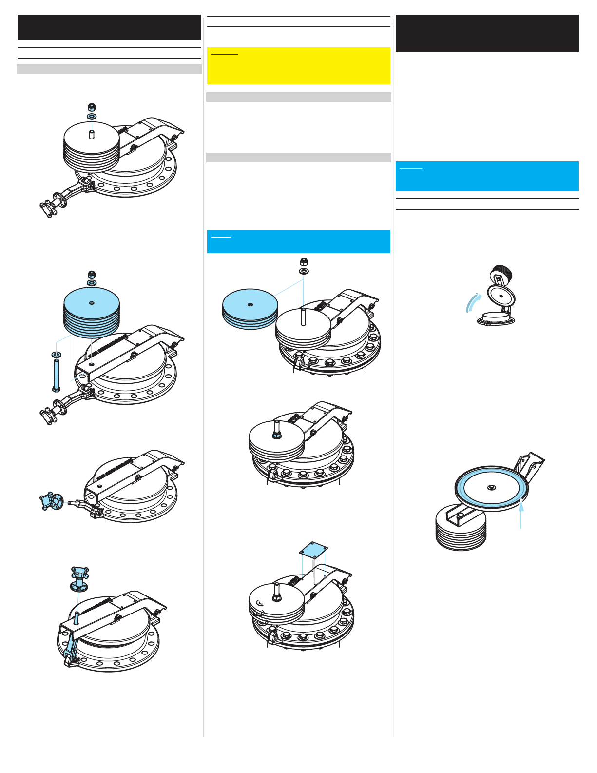
OPERATING SERIES 5000 EPRV
B1 OPERATING TRANSPORT LOCK
TOOLS
»2× 3/4 Box and/or Socket Wrench
1 Remove nut and top washer from weight hanger bolt.
2 Remove weights and weight hanger bolt. Keep these
parts together and transport along with the tank to be
reinstalled at the final destination before the tank is
placed into service.
3 Remove the locking knob.
4 Lift the EPRV arm and place the locking arm stud
through the weight hole in the EPRV arm and replace
the locking knob and tighten hand tight.
5 Once the tank has been moved, and before it is placed
into service, perform these steps in reverse to remove
the transport lock and replace the set pressure weights.
B2 CHANGING THE SET PRESSURE
The set pressure of the EPRV can be changed by adding or
removing weight plates.
NOTICE: WHEN THE SET PRESSURE IS CHANGED
FROM THE FACTORY SETTING THE PRODUCT TAG
MUST BE CHANGED TO REFLECT THE NEW SET PRES
SURE, RATED RELIEVING PRESSURE AND RELIEVING
CAPACITY.
TOOLS
»2× 3/4 Box and/or Socket Wrench
»1× Flat Head Screw Driver
»1× Pliers
»1× Small Hammer to drive rivets
PARTS REQUIRED
»1× Installed EPRV
»1× EPRV Weight Change Kit (*)
(*) Sized per application. Call for more information.
1 Remove the weight hanger nut and top washer, and
add or remove weights to achieve the desired new set
pressure.
NOTE: THE SET PRESSURE OF THE EPRV WITH NO
WEIGHTS INSTALLED IS 1 OZSI AND INCREASES WITH
THE ADDITION OF WEIGHT PLATES.
2 Replace the weight hanger nut and top washer.
3 Remove the product tag and drive rivets with the flat
head screw driver and pliers and replace with the new
product tag included in the weight change kit with new
drive rivets.
PART C
MAINTAINING SERIES 5000
EPRV
Generally, the more active the vent action of the EPRV,
the more frequent re-lubrication should be performed.
Re-lubrication requirements are application specific, and
influenced by the following variables:
»Chemical Exposure
»Presence of Contaminants
»Elevated Pressure
»High Flow Velocity
»Elevated Temperature
»Utilization
NOTE: 4561 SEVERE SERVICE GREASE IS FACTORYAP
PLIED AT THE TIME OF ASSEMBLY. RELUBRICATION
USING THE SAME PRODUCT IS STRONGLY RECOM
MENDED FOR FIELD RELUBRICATION.
C1 INSPECTION AND RELUBRICATION
1 For a thorough cleaning, inspection and re-lubrication
of the EPRV the lever arm can be removed following
part C2 steps 1-3. For a quick cleaning, inspection and
re-lubrication the EPRV arm and lid can be held open
by hand while maintenance is performed.
2 Inspect the seal. A ring shaped indentation from the
pallet seat in the seal is normal and improves the
sealing performance of the valve. If seal replacement
is required, proceed to part C2. The seal should be
replaced if there are any signs of
»cracking,
»erosion,
»swelling,
»multiple intersecting indentations
INDENT OK
3 If the seal does not require replacing, clean all
contaminants and old grease off of the seal.
4 Re-lubricate by applying an even coating of 4561
Severe Service Grease to the sealing surface.
Reassemble and lower the EPRV to its seated position.
Series 5000 EPRV (8 - 12”) Installation, Operation and Maintenance Guide - Oct-2021 3
C2 REPLACING PRESSURE SEAL
TOOLS
»1× 7/16 Box Wrench
»2× 3/4 Box and/or Socket Wrench
»1× Pliers
PARTS REQUIRED
»1× Replacement Gasket
»1× Hawkeye Severe Service Grease
1 If leaving the weight plates installed on the lever arm
make it too difficult to lift or maneuver, remove the
weight plates by removing the weight retention nut and
washer. Otherwise the seal can be replaced without
removing the weight plates by proceeding to step 4.
2 Remove the EPRV lever arm hinge pin with the pair of
pliers.
3 Remove the lever arm and pallet assembly and flip
over for access to the seal.
4 Remove the seal retention bolt, washer and plate with
the 7/16 box wrench.
5 Replace the old seal with the new seal.
6 Reinstall the seal retention plate washer and bolt.
Tighten the bolt until the seal retention plate contacts
the EPRV lid. Tighten snug.
7 Grease the seal face with Hawkeye Severe Service
Grease.
8 Reassemble the EPRV and return to service.
C3 TROUBLESHOOTING
PROBLEM: Vent is Leaking or Frequently
Opening
Symptom Of Solution
Unlubricated
Pressure Seal
Perform the inspection and re-
lubrication procedures detailed
in C1.
Worn or Damaged
Pressure Seal
Set pressure set too
close to operating
pressure
Ensure that the set pressure
of the Series 5000 EPRV is
sufficiently above the operating
pressure of the tank.
PROBLEM: Vent is not opening
Symptom Of Solution
Set pressure set too
far from operating
pressure
Ensure that the set pressure
of the Series 5000 EPRV is
sufficiently below the desired
relieving pressure and the
design pressure of the tank.
C4 BOLTING SEQUENCE
5
6
7
8
1
9
10
11
12
2
4
310 ANSI 150#
12 ANSI 150#
5
6
7
8
19
10
11
12
13
14
15
16
2
3
4
8 API 12B
Series 5000 EPRV (8 - 12”) Installation, Operation and Maintenance Guide - Oct-20214
Contents © Hawkeye Industries Inc. This document is uncontrolled, and is
subject to change without notice. Please refer to www.hawk-eye.com for the
most up-to-date product information.
2110 70 Ave NW
Edmonton, AB, Canada T6P 1N6
Toll Free: (800) 910-4295
Phone: (780) 490-4295
Fax: (780) 490-4290
www.hawk-eye.com
Printed in Canada.

Popular Tank Equipment manuals by other brands

Kemper FK-5 installation instructions

Kemper

Kemper FK-5 installation instructions

Graco 234414 instructions

Graco

Graco 234414 instructions

TransTank SuperReel Operator's handbook

TransTank

TransTank SuperReel Operator's handbook

Regulus PS2F 3000 N25 Installation and operation manual

Regulus

Regulus PS2F 3000 N25 Installation and operation manual

Graco SHARPE A Series Instructions - parts

Graco

Graco SHARPE A Series Instructions - parts

Sears 390.291352 owner's manual

Sears

Sears 390.291352 owner's manual

JohnDow Industries JDI-AFT106 Operator's manual

JohnDow Industries

JohnDow Industries JDI-AFT106 Operator's manual

FFS EVO 400 Replacement guide

FFS

FFS EVO 400 Replacement guide

JohnDow Industries JDI-AGT40 user manual

JohnDow Industries

JohnDow Industries JDI-AGT40 user manual

Vetus ILT120B installation manual

Vetus

Vetus ILT120B installation manual

WELBA TW-32 Installation and operating instructions

WELBA

WELBA TW-32 Installation and operating instructions

Kemper FK-5 installation instructions

Kemper

Kemper FK-5 installation instructions

JohnDow Industries JDI-FST15 user manual

JohnDow Industries

JohnDow Industries JDI-FST15 user manual

Reverso AFP-150 manual

Reverso

Reverso AFP-150 manual

Alfalaval HTC instruction manual

Alfalaval

Alfalaval HTC instruction manual

VAREM AQUAFILL HS instruction manual

VAREM

VAREM AQUAFILL HS instruction manual

TransTank FloodRite Operator's handbook

TransTank

TransTank FloodRite Operator's handbook

Regulus RBC 200 Installation and operation manual

Regulus

Regulus RBC 200 Installation and operation manual

manuals.online logo
manuals.online logoBrands
  • About & Mission
  • Contact us
  • Privacy Policy
  • Terms and Conditions

Copyright 2025 Manuals.Online. All Rights Reserved.