Haws TWBS.SH Guide

07/08 Model TWBS.SH Page 1 of 6
No. 2080374
(
6
)
1455 Kleppe Lane Sparks, NV 89431-6467 (775) 359-4712 Fax (775) 359-7424
HAWS AG Bachweg 3 CH-3401 Burgdorf Switzerland
Haws Mfg. Pte Lt. 2A Sungei Kadet Drive Singapore 729554
Avlis-Avenido Senador, Testonio Vilela 505 Jardim Aeroporto Itu, S.P. 13304-550 Brasil
Model TWBS.SH
Tempered Water Blending System
INSTALLATION, OPERATION
&
MAINTENANCE INSTRUCTIONS
LIMITED WARRANTY
HAWS®warrants that all of its products are guaranteed against defective material or poor
workmanship for a period of one year from date of shipment. HAWS liability under this
warranty shall be discharged by furnishing without charge F.O.B. HAWS Factory any
goods, or part thereof, which shall appear to the Company upon inspection to be of
defective material or not of first class workmanship, provided that claim is made in writing
to company within a reasonable period after receipt of the product. Where claims for
defects are made, the defective part or parts shall be delivered to the Company, prepaid,
for inspection. HAWS will not be liable for the cost of repairs, alterations or replacements,
or for any expense connected therewith made by the owner or his agents, except upon
written authority from HAWS, Sparks, Nevada. HAWS will not be liable for any damages
caused by defective materials or poor workmanship, except for replacements, as provided
above. Buyer agrees that Haws has made no other warranties either expressed or implied
in addition to those above stated, except that of title with respect to any of the products or
equipment sold hereunder and that HAWS shall not be liable for general, special, or
consequential damages claimed to arise under the contract of sale.
The emergency equipment manufactured by HAWS is warranted to function if installation
and maintenance instructions provided are adhered to. The units also must be used for
the purpose, which they were intended. This product is intended to supplement first-aid
treatment. Due to widely varying conditions HAWS cannot guarantee that the use of this
emergency equipment will prevent serious injury or the aggravation of existing or prior
injuries.
NO OTHER WARRANTIES EXPRESSED OR IMPLIED ARE AUTHORIZED, PROVIDED
OR GIVEN BY HAWS.
NOTE TO INSTALLER: Please leave this information with the Maintenance Department.
SHOULD YOU EXPERIENCE DIFFICULTY WITH THE INSTALLATION OF THIS
MODEL, PLEASE CALL: 1-800-766-5612
FOR PARTS CALL: 1-800-758-9378
(U.S.A. AND CANADA ONLY) MONDAY-THURSDAY: 6:00 A.M. – 4:00 P.M. PST
FRIDAY: 6:00 A.M – 1:00 P.M. PST

07/08 Model TWBS.SH Page 2 of 6
I. WHAT IS THE HAWS TWBS.SH?
The HAWS TWBS.SH is a patented tempered water mixing system (US Patent # 5350112) for use with
emergency drench shower and eyewash stations where cold and hot water is thermostatically blended to
provide a discharge of tempered water at a selected temperature. The TWBS.SH is a thermo-mechanical
system with thermally activated and pressure-activated safety features, which do not require electricity for
operation. These safety features utilize back-up control valves that ensure a substantial water flow
without the risk of scalding, even in the event of main mixing valve failure. Additionally, a temperature limit
control valve detects the outflow temperature and helps to reduce the discharge temperature should
excessive temperature conditions occur.
II. HOW DOES THE TWBS.SH OPERATE?
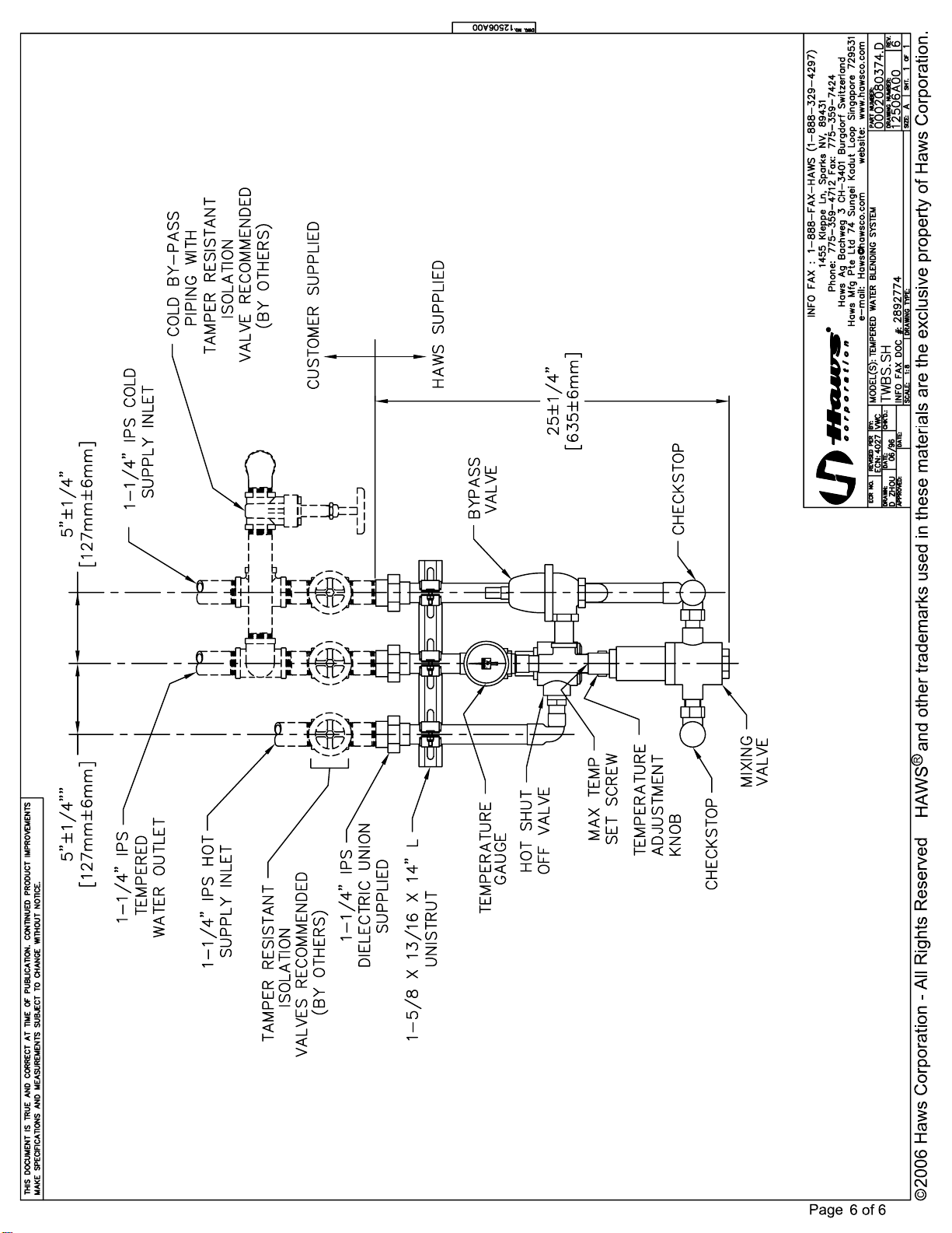
The heart of the WTWBS.SH system is the thermostatically controlled mixing valve. It includes an integral
strainer and check valves, and has an adjustable temperature control, which is typically set at 80°F. The
main mixing valve includes a connection to a cold water supply and a hot water supply, with the ability to
provide a discharge outflow of water at a selected/blended temperature level. On the hot water inlet side
of this mixing valve we include a high limit temperature control valve, which senses the temperature of the
discharge flow. When the discharge flow temperature exceeds our factory pre-set limit of 85°F, this
control valve closes and/or modulates, thus reducing the hot water flow being sent to the mixing valve.
On the cold-water inlet side, we include a flow control bypass valve, which is responsive to the pressure
differential between the cold water supply and the discharge of the tempered water. Should the main
mixing valve fail to produce the required mixed flow through the discharge line, the bypass valve senses
this and opens up, allowing the incoming cold water to bypass the system and proceed directly to the
emergency shower and/or eyewash. These two back-up components permit the temperature level of
tempered water to be maintained without undesirable temperature reductions/fluctuations experienced in
most failures. They also permit the flow of cold water should the mixing valve fail altogether.
III. PERFORMANCE FEATURES OF THE HAWS TWBS.SH SYSTEM
Essentially, the HAWS TWBS.SH provides fail-safe protection against scalding or blocked flow. There are
three types of failures that can occur with any mixing valve system. They are as follows:
1) The mixing valve can stick in an open position and provide an unregulated flow of hot
water.
2) The mixing valve can stick in a position, which allows an unregulated flow of cold water.
3) The mixing valve can fail so as to provide an insufficient and/or blocked flow of either hot
or cold water.
The unique HAWS TWBS.SH answers the above three failure modes in the following manner:
Fail-safe Performance Mode # 1 Too much Hot Water
The primary safety in the HAWS TWBS.SH is the high limits hot shut-off valve, or the temperature limit
control valve, which senses outlet temperatures and modulates the incoming hot water to maintain an
outlet temperature below 85°F. This high limit shut-off valve is non-adjustable (tamperproof) and provides
a regulated reduction in the temperature level of the discharge flow. This high temperature limit valve
provides the first backup for regulating the temperature of the discharge flow in the event of mixing valve
malfunction (i.e., too much hot water).
Fail-safe Performance Mode # 2 Unregulated Full Flow of Cold Water
The HAWS TWBS.SH answers this condition in two ways. When improper mixing valve operation occurs
and produces a restricted flow (i.e., a pressure differential between the cold water supply and the
discharge tempered water outflow), the flow limit control valve opens to permit the direct flow of cold
water past the main mixing valve and into the system. Additionally, the temperature control valve will
sense a reduction in the temperature of the discharging tempered water and will open to permit an
increased flow of hot water into the system. In this case, the HAWS TWBS.SH can help to produce warm
water even when the pressure relief bypass valve is operating. (The high temperature valve opens so as
to assist in maintaining a degree of tempered water out).

07/08 Model TWBS.SH Page 3 of 6
Fail-safe Performance Mode # 3 Unregulated Full Flow of Cold Water
In the event that water flow through the main mixing valve is obstructed altogether, resulting in a
significant reduction in the flow rate out of the discharge line, the flow limit control valve (bypass valve)
responds to this pressure differential (set for 25 PSI) and permits the complete bypass and flow of cold
water through the system.
The HAWS TWBS.SH is designed to accurately, reliably, and safely mix hot and cold water to
provide warm water for emergency safety shower and eyewash. It features three back-up
conditions that assist in regulating the discharge flow rate and temperature in the event of a
mixing valve malfunction. Two of the three include water tempered to some degree and none
require the need for any electrical supply.
IV. CAPACITY
HAWS TWBS.SH produces up to 40 GPM at a pressure drop of 36 PSI and requires 26-PSI dynamic
pressure differential to produce 30 GPM. It requires 15 PSI of dynamic pressure differential to produce 20
GPM. The eyewash temperature at 6 GPM remains steady 80º F while there may be slight fluctuation
upon demands over 30 GPM (shower application).
TWBS.SH Flow rate in various pressure differentials
Water Flow Rate (gpm)
0 5 10 15 20 25 30 35
Pressure Drop Across TWBS.SH (Δpsi)
0
5
10
15
20
25
30

07/08 Model TWBS.SH Page 4 of 6
V. INSTALLATION
A). APPLICATION
The standard TWBS.SH is sized to blend enough water for one shower, five eyewash units, or
ten face wash units at a time. If there is a good chance that two or three showers might be used
at the same time, our High Flow TWBS should be specified.
This Tempered Water Blending System should be installed in close proximity to shower/eyewash.
It should be clearly identified, with easy access and free from obstructions. Supply lines must be
heat traced if subject to freezing temperatures. If the piping network is through a cold area, piping
should be heat-traced with self-regulating heat tape, or recirculated through the TWBS.SH. Any
heat-traced piping should be protected with scald protection bleed valves. Additionally, should the
TWBS.SH be mounted at a distance greater than 50 feet from the shower and/or eyewash, these
runs should be evaluated by a plumbing engineer. Complicated chains of showers, long piping
runs and recirculating loops should all be evaluated by a qualified engineer.
B). RECOMMENDED TOOLS
Pipe joint sealant, adjustable pipe wrenches, (2) rust resistant wall anchors (3/8" diameter).
C). WATER SUPPLY
The minimum recommended supply lines are 1-1/4" IPS COLD and 1-1/4" IPS HOT. Cold supply
temperatures should range from 35°F to 75°F. Hot supply temperatures should range from 110°F
to 180°F. For best operation, hot water should be at least 20°F above desired set point. A
minimum of 40 GPM at 35-PSI dynamic pressure must be provided. Inlet and outlet connections
are 1-1/4" IPS dielectric unions. We recommend a manual bypass loop with appropriate tamper
resistant shut-off valves to allow for tempered water system maintenance or service without
interrupting emergency shower/eyewash operation.
IMPORTANT: Install a check valve or thermal trap at cold water inlet of hot water tank: Hot
water must never enter cold inlet of tempering system.
D). PROCEDURE USE PIPE SEALANT ON ALL WATER CONNECTIONS.
Step 1: Mount unit on wall. Bolt dia. 3/8" fasteners through internal strut support frame.
Step 2: Flush supply piping prior to connecting to inlet unions. Connect outlet union to piping
leading to shower/eyewash. Check for leaks.
Step 3: TEST FUNCTION OF UNIT
A). Turn on one eyewash. Carefully monitor initial few minutes of flow with hand in
eyewash flow. Check to insure initial flow does not contain brief shots of hot
water. If any problems, see troubleshooting.
B). Adjust mixing valve cooler while watching outlet temperature gage to insure
proper function of mixing valve. Gage should register temperature drop as valve
is adjusted to lower temperature.
C). Adjust mixing valve to maximum hot to test function of anti-scald protection valve
and cold by pass valve. Maximum temperature should be limited to 85°F + 5°F.
Adjust mixing valve cooler until outlet temperature reaches 80°F.
IMPORTANT: REPEAT TEST PROCEDURE WEEKLY!

07/08 Model TWBS.SH Page 5 of 6
VI. TROUBLE-SHOOTING
TROUBLESHOOTING
PROBLEM REPAIR CHECKLIST
1. Outlet temperature too hot.
1. a. Insure cold and hot supplies are plumbed
to proper inlets. Check cold water supply
temperature. If cold water supply is too hot
due to solar heating, install anti-scald bleed
valves in hot sections of cold water supply
line.
b. Adjust main mixing valve cooler. If supply
water temperatures are within correct
ranges and main mixing valve will not
adjust to provide desired outlet
temperature, replace mixing valve. If outlet
temperature is above 90°F, replace anti-
scald hot water shut-off valve.
2. Outlet temperature starts too hot
then cools down. 2. a. Check inlet cold line. If hot water is
siphoning into cold line, install check valve
or thermal trap in line.
b. If cold supply has hot spots due to solar or
other heating, install anti-scald bleed valves
in hot sections of line.
3. Outlet temperature too cold. 3. a. Insure proper supply of hot water
b. Adjust main mixing valve warmer
c. Clean inlet strainers in mixing valve
assembly by removing bonnet with 2-1/4”
wrench at the bottom of check stop.
d. Under high volume demand (26 gpm or
more) the blending system outlet
temperature will slightly drop.
e. If mixing valve will not adjust to proper
temperature and both hot and cold supply
temperatures are within specified ranges,
replace mixing valve.
f. Check stop(s) may be closed. Open check
stop by turning stem counter clockwise with
a slotted screwdriver.
VII. REPLACEMENT PARTS
Description
Quantity
Temperature Gage, 1/2” 1
Mixing Valve 1
Bypass Valve, 1” 1
Hot Shut-off Valve, 1” 1
© 2006 Haws®Corporation – All Rights Reserved
HAWS® and other trademarks usedin these materials are the exclusive property of Haws Corporation.

Table of contents
Other Haws Industrial Equipment manuals
Popular Industrial Equipment manuals by other brands

Zehnder Rittling
Zehnder Rittling ComfoFond-L installation manual

U-Line
U-Line H-3797 manual

Boston gear
Boston gear BETA II manual

visplay
visplay Multi-Lane Assembly and operating instructions

Festo Pneumatic
Festo Pneumatic LFR-C-S-B Series operating instructions

Dodge
Dodge SLEEVOIL 2-15/16 instruction manual