HB Products HBOR User manual

Instruction manual - HBOR –Oil Pot Controller (001UK) 1 / 14
WE INCREASE
UPTIME AND EFFICIENCY
IN THE REFRIGERATION INDUSTRY
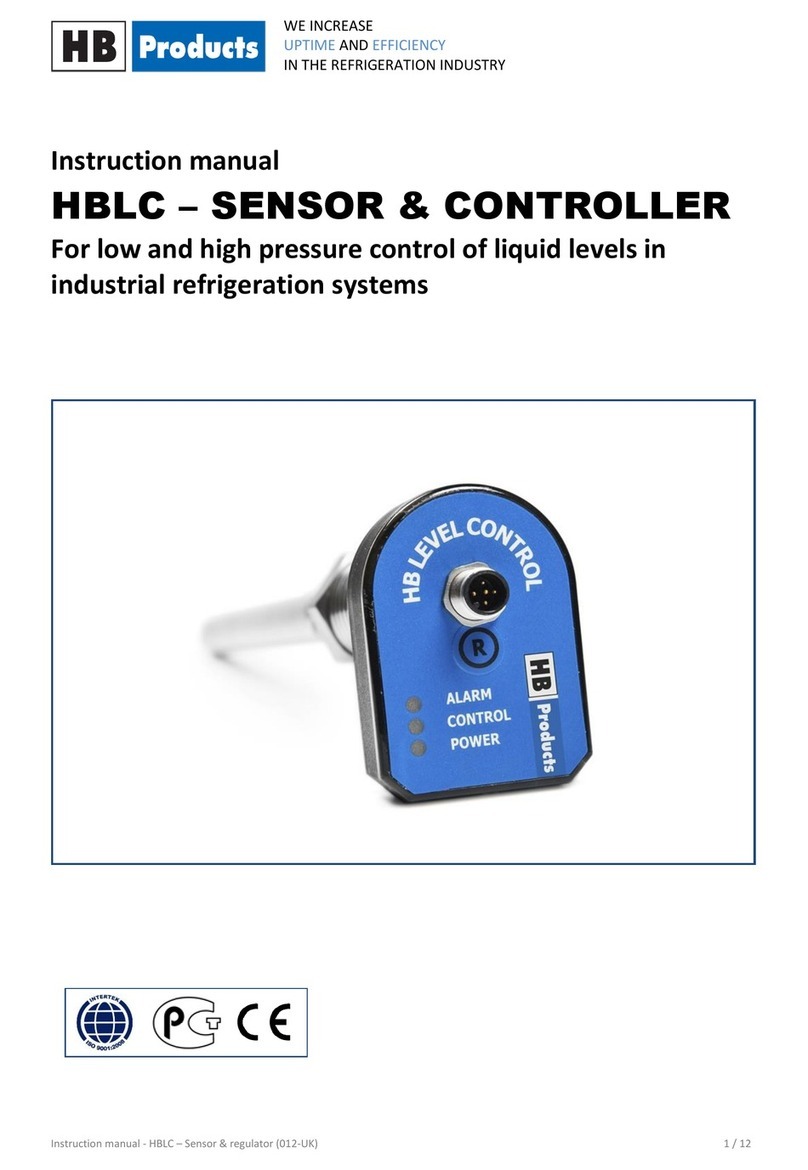
Instruction manual
HBOR - OIL POT CONTROLLER
For oil level control in oil pots

Instruction manual - HBOR –Oil Pot Controller (001UK) 2 / 14
WE INCREASE
UPTIME AND EFFICIENCY
IN THE REFRIGERATION INDUSTRY
Table of contents
Safety Instructions...........................................................................3
Introduction.....................................................................................4
Measurement Principle ...................................................................4
Design ..............................................................................................4
Software ..........................................................................................4
Technical Data .................................................................................5
Functionality.................................................................................... 5
Installation Guide ............................................................................6
Mounting Guide...............................................................................6
Electrical connection .......................................................................8
LED Indication & Calibration............................................................8
Installation of HBOC Configuration Tool .......................................10
PC Configuration............................................................................11
Function description –setup parameters .....................................11
Fault Detection ..............................................................................13
Spare parts.....................................................................................14
Further Information.......................................................................14

Instruction manual - HBOR –Oil Pot Controller (001UK) 3 / 14
WE INCREASE
UPTIME AND EFFICIENCY
IN THE REFRIGERATION INDUSTRY
Safety Instructions
CAUTION! Always read the instruction manual before commencing work! Heed all warnings to the letter!
Installation of HBOR requires technical knowledge of both refrigeration and electronics. Only qualified
personnel should work with the product. The technician must be aware of the consequences of an
improperly installed sensor, and must be committed to adhering to the applicable local legislation.
If changes are made to type-approved products, this type approval becomes void. The product's input and
output as well as its accessories may only be connected as shown in this guide. HB Products assumes no
responsibility for damages resulting from not adhering to the above.
Explanation of the symbol for safety instructions. In this guide, the symbol below is used to point out
important safety instructions for the user. It will always be found in places in the chapters where the
information is relevant The safety instructions, and particularly the warnings, must always be read and
adhered to.
CAUTION! Refers to a possible limitation of functionality or risk of use.
NOTE! Contains important information about the product and provides further tips.
The person responsible for operation must commit to adhering to all the legislative
requirements, preventing accidents, and doing everything so as to avoid damage to
people and materials.
Intended use, conditions of use. HBOR level controller is made for continuous control of oil level in oil pots.
If HBOR is to be used in a different way or with another purpose, and if the operation of the product in this
function is determined to be problematic, prior approval must be obtained from HB Products
Prevention of collateral damage Make sure that qualified personnel assess any faults and take necessary
precautions before attempting to make replacements or reparations, so as to avoid collateral damage.
Environmentally correct behaviour, disposal instruction: HBOR is built so that the modules can easily be
removed and sorted for disposal.

Instruction manual - HBOR –Oil Pot Controller (001UK) 4 / 14
WE INCREASE
UPTIME AND EFFICIENCY
IN THE REFRIGERATION INDUSTRY
Introduction
HBOR is an intelligent sensor with a built-in
microprocessor. It is designed to detect and
control oil levels in oil pots.
Apart from the sensor function, it also has a built-
in controller.
The controller can be setup with all the
parameters that are necessary to directly
regulate solenoid valves for oil level control.
Measurement Principle
The sensor is a capacitative sensor. The capacitative measurement principle is based on the electrical
properties in the proximity of a capacitor. A capacitor is an electrical component that is capable of building
and sustaining an electrical charge
Principally, a capacitor consists of two plates.
When a charge is applied to a plate, the other
plate will be charged with the opposite polarity
and retain the charge until it has been grounded.
The magnitude of the charge (the capacitance)
that can be generated depends, among other
things, on what is found between the plates.
The substance between the plates is referred to
as a dielectric.
In front of the two plates, the sensor for level
measurement is shaped as a cylindrical rod.
When liquid covers the sensor, the measured
capacity is changes.
.
The conductivity of a material can vary depending
on temperature, chemical composition, and the
homogeneity of the material, and therefore it can
in some cases require a different factory
calibration.
Design
The sensor consists of a mechanical part and an electronic part. These are easily separated by loosening 2
grub screws, or for mechanisms with mounting tabs, by pressing the electronic part in towards the
mechanical part and turning the housing counter-clockwise until a wave washer pushes it from the
mounted position. The electronic part is designed in accordance with IP65 waterproof rating and to resist
vibrations.
The mechanical part is produced in AISI304/PTFE and tested to withstand high pressure.
Software
The sensor is supplied with the latest firmware. The sensor is configured with a configuration tool, using a
PC. It is capable of determining on its own the current version which was delivered.
The newest version of the tool is backwards compatible.
It is not possible to update the software on a sensor which has already been delivered.

Instruction manual - HBOR –Oil Pot Controller (001UK) 5 / 14
WE INCREASE
UPTIME AND EFFICIENCY
IN THE REFRIGERATION INDUSTRY
Technical Data
Supply:
Voltage: 24 V DC ±10%
Current draw: Max 30 mA
Connector: M12 –5 pins
DIN 0627
Valve control:
Potential-free relay output: Max 1 A (24W)
Cable length: 3 m
Cable size: 3 x 0,75 mm2
Cable connection: Screw terminals
Cable glands: PG7 / M8
Installation conditions:
Ambient temperatures: -30…+50°C
Max. operational pressure: 150 bar
Waterproof rating: IP65
Vibrations: IEC 68-2-6 (4g)
Authorisations:
EMC Emission: EN61000-3-2
EMC Immunity: EN61000-4-2
Mechanical specifications:
Thread connection: ¾”
Materials –mechanical parts: AISI304/PTFE
Materials –electronic parts: Nylon 6 (PA)
Weight: 500 g
Housing design: Angled
Configuration & indication:
Configuration With a PC
LED indication green, yellow, and red
Supply cable specifications:
M12 cable –5 m: HBxC-M12/5
Plug type –cable: Angle - 90°
Cable type: PVC-OB grey
Cable size: 5 x 0,34 mm2
Cable glands: PG7 / M8
Cable approval: CSA
Accessories:
Magnetic valve: V150
Functionality
HBOR is designed for oil detection and control in oil pots
NOTE! All terminals are protected against incorrect termination with a supply voltage of up to
40V. If the supply voltage is greater than 40 V, the electronics will be damaged.

Instruction manual - HBOR –Oil Pot Controller (001UK) 6 / 14
WE INCREASE
UPTIME AND EFFICIENCY
IN THE REFRIGERATION INDUSTRY
Installation Guide
The following applies:
1) The sensor must be installed in a horizontal position.
2) During installation, check the sensor's length as well as its placement with the refrigeration
compressor manufacturer or the oil separator producer. Oil pockets may not form around
the sensor, and there must be a gap of at least 2mm between the sensor and the other
mechanical parts.
CAUTION! In case of welding work on the unit, please make sure that proper earthing is carried
out to avoid damaging the electronics.
Accessories:
The sensor can be supplied with the following accessories:
1) Solenoid-V100 - ¼” magnetic valve for opening/closing inflow or outflow of oil. The valve has a 24
VDC supply and is designed for pressures up to 100 bar. The valve has a Kv value of 1.5 l/min.
Installation of the magnetic valve: So as to be able to supply the magnetic valve directly, it must be
installed within 3 metres of the sensor.
Mounting Guide
HBOR is mounted on an oil pot. The sensor is sealed with Teflon tape or liquid gasket before installation.
Dependent upon the thread type, the gasket consists of:
NPT thread = Teflon tape or liquid gasket
BSPP thread = Gasket

Instruction manual - HBOR –Oil Pot Controller (001UK) 7 / 14
WE INCREASE
UPTIME AND EFFICIENCY
IN THE REFRIGERATION INDUSTRY
For installation, there is required a 2.5mm Allen key, a
shifting spanner, as well as gasket material depending on
the thread type.
Loosen two set screws, or for mechanisms with
mounting tabs, press the electronic part in towards
the mechanical part and turn the housing counter-
clockwise until a wave washer pushes it from the
mounted position.
Separate the electronic part from the mechanical part.
Teflon or liquid gasket is applied to the conical
thread. Cylindrical thread is installed with gasket.
Mount the sensor on the oil pot. Tighten thread,
depending on thread type.
The electronic part is installed on the mechanical
part and secured with 2 screws.

Instruction manual - HBOR –Oil Pot Controller (001UK) 8 / 14
WE INCREASE
UPTIME AND EFFICIENCY
IN THE REFRIGERATION INDUSTRY
Electrical connection
HBOR can be supplied with direct control of the magnetic valve, or it can be connected to the central
control via the sensor's control/alarm output. See the diagram below.
The sensor has a control function and regulates the flow of oil independent of other parts of the system.
The function starts to work when the supply is connected. The control function can be
activated/deactivated via an external run signal with "Run in" (clamp 5) and -24 V (clamp 2).
LED Indication & Calibration
LED indication:
1) 3 x green LEDs indicate oil level
2) Green Power LED indicates 24 V DC supply; blinks during
operation. If "run-in" is not used, this function must be
deactivated in the tool.
3) Yellow LED indicates supply is open to magnetic valve
4) Red LED indicates ALARM

Instruction manual - HBOR –Oil Pot Controller (001UK) 9 / 14
WE INCREASE
UPTIME AND EFFICIENCY
IN THE REFRIGERATION INDUSTRY
LED signal
ON/OFF/Frequency
Functionality
Green (3x)
ON
Oil detected
Flash
Turbulence in the compressor housing
OFF
Oil is not detected
Green POWER
ON
Supply
Flash
In operation or
when the sensor is connected to HBOC Tool. (Red and yellow LED
also blink)
OFF
No supply
Yellow
ON
Activation/supply to the magnetic valve
OFF
Magnetic valve is not being supplied
Red
ON
Alarm. Activated automatically according to a calculated time
span if oil has not been detected (oil cycle x alarm counter = Time
before alarm goes off). Output relay (pin 3 & 4) is activated.
OFF
Oil level reached in accordance with the calculated time span /
number of oil cycles.
Calibration:
"R" for factory reset and calibration:
Alarm is reset by pressing "R" for 5 seconds.
Calibration instructions:
HBOC is pre-calibrated upon delivery. If one uses common lubricating oils in the refrigeration compressor,
calibration is normally not necessary. If the sensor is too sensitive or does not register oil at all, calibration
should be carried out.
Calibration can only be carried out if the function "Calibration" is set to ON in HBOC Tool. It is carried out
during normal system operation.
The sensor is calibrated by pressing "R" 5 times.
Calibration can alternatively be carried out before start-up or during fault detection, by having an extra
mechanism. Without stoppages or loss of pressure.
The electronics are installed on the extra mechanism and calibrated when vertically submerged to 50% in
the same type of oil that is used in the compressor housing. The electronics can then be re-installed in the
system.
After final calibration, one should consider setting "Calibration" to OFF

Instruction manual - HBOR –Oil Pot Controller (001UK) 10 / 14
WE INCREASE
UPTIME AND EFFICIENCY
IN THE REFRIGERATION INDUSTRY
Installation of HBOC Configuration Tool
1) The tool can be downloaded for free. Request access
to download the tool by sending an email to
Instructions for installation are sent together with the
password.
2) Download HBOC Tool and install it on a PC. System
requirements: Windows-based PC with Java installed.
If Java is not installed, it is possible to do this in
connection with the installation of the HBOC tool.
An internet connection is required to download it.
Minimum screen resolution is 1366x768
3) Follow the instructions during setup of the program.
4) Connect the USB cable, HBxC-USB, to the PC. Give Windows a moment to find a driver for the USB
cable; for this to happen automatically an internet connection is required, otherwise follow the
instructions on the installation of drivers in the program "Configurations Instructions".
5) Search for USB com port. Select USB COM port in the window below. For example COM3. In the
lowermost bar, one can see that the USB com port is selected and open for communication with
the sensor. The bar changes colour from red to green when there is a connection between the
program and the USB cable.
6) Connect the cable to the sensor. The software program records the current version (see SW
xx.x.xx).
7) Connection to the sensor is complete when the green, yellow, and red sensors blink in a set
pattern.
8) The sensor's current setup can be retrieved by pressing (Show current configuration).
9) The sensor's factory settings can be reset by pressing (Reset to default).
10) All parameters can now be input. After the final selection, press "Set configuration". The selected
parameters are transferred and saved in the sensor. When this transfer is complete, an image of
the sensor appears with a message that the transfer was successful. Press OK to complete the
process.
NOTE! To be able to change the control parameters, it is necessary to have a special USB/M12
configuration cable as well as a configuration tool installed on a PC.

Instruction manual - HBOR –Oil Pot Controller (001UK) 11 / 14
WE INCREASE
UPTIME AND EFFICIENCY
IN THE REFRIGERATION INDUSTRY
PC Configuration
The sensor is supplied with the following configuration options and factory settings:
General settings
Output signal, oil feed
NO/NC
NO
Alarm delay (separator mode)
10…10.000 min
60 min
Oil cycle periods/time
1…300 s
60 s
Oil valve open time
1…300 s
10 s
Oil feed, switching hysteresis
1….10 mm
5 mm
Alarm counter (no of oil cycles)
1…100
30
Oil sensor dwell
1…30 s
10 s
Calibration function
ON / OFF
OFF
Oil cycle function
ON/OFF
ON
CAUTION! Factory settings do not guarantee safe operation, since the configuration parameters
depend on the type of compressor/separator.
NOTE! If the program is shut down and started up again, the cable to the sensor must be
disconnected (M12 plug) and reconnected.
Function description – setup parameters
Oil pot alarm delay in minutes:
Time that elapses before the sensor triggers the alarm for low oil level.
During normal system operation, the oil will be released in the separator; if this does not occur, it is likely
that the oil has accumulated in other areas of the system. Therefore one wants the alarm to trigger when a
certain amount of oil has not been separated within a defined period.
Oil cycle periods/time in sec:
The time for the frequency with which the sensor checks for oil. Typically, one wants a certain period
between when the oil-return-valve lets oil into the crankshaft housing and how long the level is accepted
under.
If the period is (too) short, oil will be filled up more frequently.
Oil valve open time in sec:
Number of seconds during which the supply voltage to the oil-return-valve is open.
This should be aligned to the system pressure, pipe dimension, and size of valve.

Instruction manual - HBOR –Oil Pot Controller (001UK) 12 / 14
WE INCREASE
UPTIME AND EFFICIENCY
IN THE REFRIGERATION INDUSTRY
Filter func/time cons in sec:
An average measurement is made in programmed seconds. Can be increased in case of unstable
measurement.
Switching hysteresis factor:
Hysteresis for the contact function. Hysteresis indicates how many mm of oil can drop before the contact
function ceases. Popularly called a type of "backlash" in the system.
Oil sensor dwell:
Indicates the time from the end of hysteresis to the start of the oil cycle period.
Calibration function:
Must be connected if one wants to re-calibrate the sensor.
Following calibration, one can switch back to OFF by connecting the tool again.
The sensor is factory calibrated in PAG68. If a different oil type is used, it may need to calibrated.
Alarm output signal:
Is selected depending on whether the magnetic valve has the contact function NC or NO (Normally
closed/Normally open)

Instruction manual - HBOR –Oil Pot Controller (001UK) 13 / 14
WE INCREASE
UPTIME AND EFFICIENCY
IN THE REFRIGERATION INDUSTRY
Fault Detection
General:
Fault Detection
Fault
Reason
Correction of fault
No LED is on.
No supply to the sensor or
defective cable/plug
Check and find faults in the power
supply. Change the supply cable.
Sensor does not trigger even
though there is oil.
Quality/type of oil is different
from that used during factory
calibration.
Recalibrate the sensor.
Red alarm
Oil level has not been attained
during a number of oil cycles.
Check system oil return. Check oil
filter and magnetic valve if
necessary.
3 x Green blinks
There is oil turbulence in the
compressor housing.
Change "prel delay" to a higher
value.
No output (3 x green LED are on,
but the output signal is not
active)
Check the setup of the
parameters/which contact
function has been selected, NC or
NO (Normally closed/Normally
open)
Change the setup using the tool.
Delay in sensor activation
May be caused by gas and foam
bubbles in the system.
Check if the sensor is placed
optimally.
No detection
Fault in the electronics
Send the sensor to be repaired.
Sensor Repair
The sensor electronics are completely embedded and can therefore not be repaired.
In case of faults with the sensor, it will typically only be necessary to replace the electronics.
Complaint cases are handled by the HB Products dealers/distributors.
Their complain procedures must be followed before returning the sensor.
NOTE! Fault detection on the electronics and/or replacement of the electronics can be
carried out without releasing pressure on the system or removing the mechanical part of the
sensor

Instruction manual - HBOR –Oil Pot Controller (001UK) 14 / 14
WE INCREASE
UPTIME AND EFFICIENCY
IN THE REFRIGERATION INDUSTRY
Spare parts
Position
Type
Specification
Part number
1
Mechanical part
¾” NPT
HBSR-MEK-2
¾” BSPP
HBSR-MEK-6
2
Electronic part
PC-programmable
HBOR/C-EL
Further Information
For further information, please visit our website, www.hbproducts.dk, or send an email to:
Other manuals for HBOR
1
Table of contents
Other HB Products Controllers manuals
Popular Controllers manuals by other brands
MESA ENGINEERING
MESA ENGINEERING MIDI MATRIX owner's manual
OEZ
OEZ SM1003 Series Instructions for use
ABB
ABB ACS55-01E-01A4-2 user guide

Athena
Athena RMB/1 Operation manual
Johnson Controls
Johnson Controls VFD66 Series Product/Technical Bulletin
Siemens
Siemens SINUMERIK ONE PPU 1740 Series Equipment manual
