HB HBLC-Fgas User manual
Wire and Flex level sensor manual 04 October 2021 HBproducts.dk 1
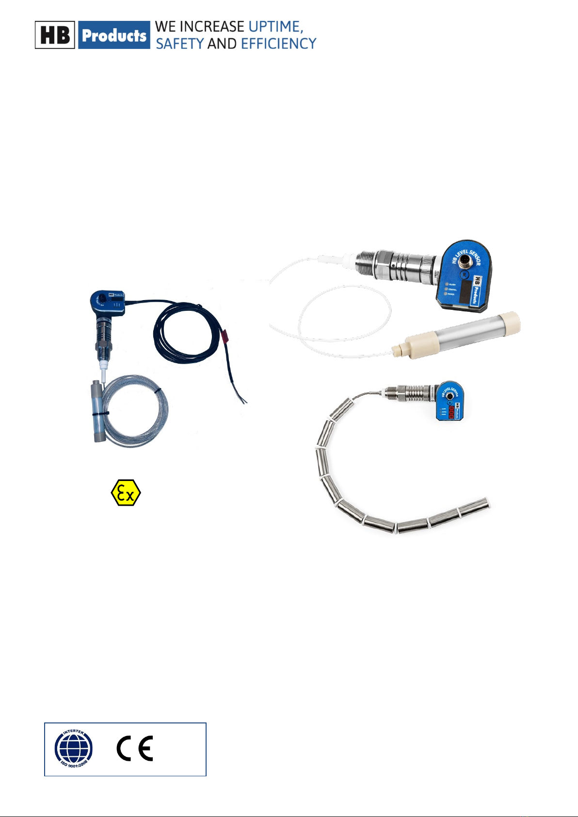
Wire and Flex are intelligent liquid level sensors which can be installed in a vessel or in a standpipe. For the Wire sensor the
sensor element is a stainless steel wire insulated with PTFE and for the Flex sensor the element is a stainless steel wire
mounted with steel tube elements to increase the sensivity. Both sensors can to be mounted directly in a stand pipe. If they
need to be installed in a vessel they need an inner pipe. Both sensors measure between the wire/tube elements and the sur-
rounding pipe.
The sensor can be installed in refrigeraon systems and similar demanding applicaons with high pressures and aggressive
uids. The sensor emits a 4-20mA analog signal, which is proporonal to the liquid level.
Introducon
Manual for all exible level sensors and wire sensors delivered be-
fore October 15th 2021
Covers: HBLT & HBSLT
• Wire sensor suited for liquids like NH3, and HFC/HFO refrigerants
• Flex sensor suited for liquids like CO2 and Hydro carbons
Can be used in refrigeraon systems and similar demanding systems.
ATEX/Ex versions included
Wire and Flex level sensor manual 04 October 2021 HBproducts.dk 2
Table of contents
Introducon...............................................................................................1
Safety Instrucons .....................................................................................2
Applicaon Examples..............................................................................3-5
Installaon Wire.........................................................................................6
Installaon Flex..........................................................................................7
Connecon diagrams ............................................................................8-12
Analog output ..........................................................................................12
Use the HB-tool for seng up the sensor ..........................................13-16
LED indicaon ..........................................................................................17
Calibraon on the sensor.........................................................................17
Fault detecon.........................................................................................18
Sensor Repair...........................................................................................18
Further Informaon.................................................................................18
Safety Instrucons
CAUTION! Always read the instrucon manual before commencing work! Heed all warnings to the leer! Installaon of the
sensor requires technical knowledge of both refrigeraon and electronics. Only qualied personnel should work with the
product. The technician must be aware of the consequences of an improperly installed sensor and must be commied to
adhering to the applicable local legislaon.
If changes are made to type-approved equipment, this type approval becomes void. The product's input and output, as well
as its accessories, may only be connected as shown in this guide. HB Products assumes no responsibility for damages re-
sulng from not adhering to the above.
Explanaon of the symbol for safety instrucons. In this guide, the symbol below is used to point out important safety
instrucons for the user. It will always be found in places in the chapters where the informaon is relevant. The safety in-
strucons and the warnings in parcular, must always be read and adhered to.
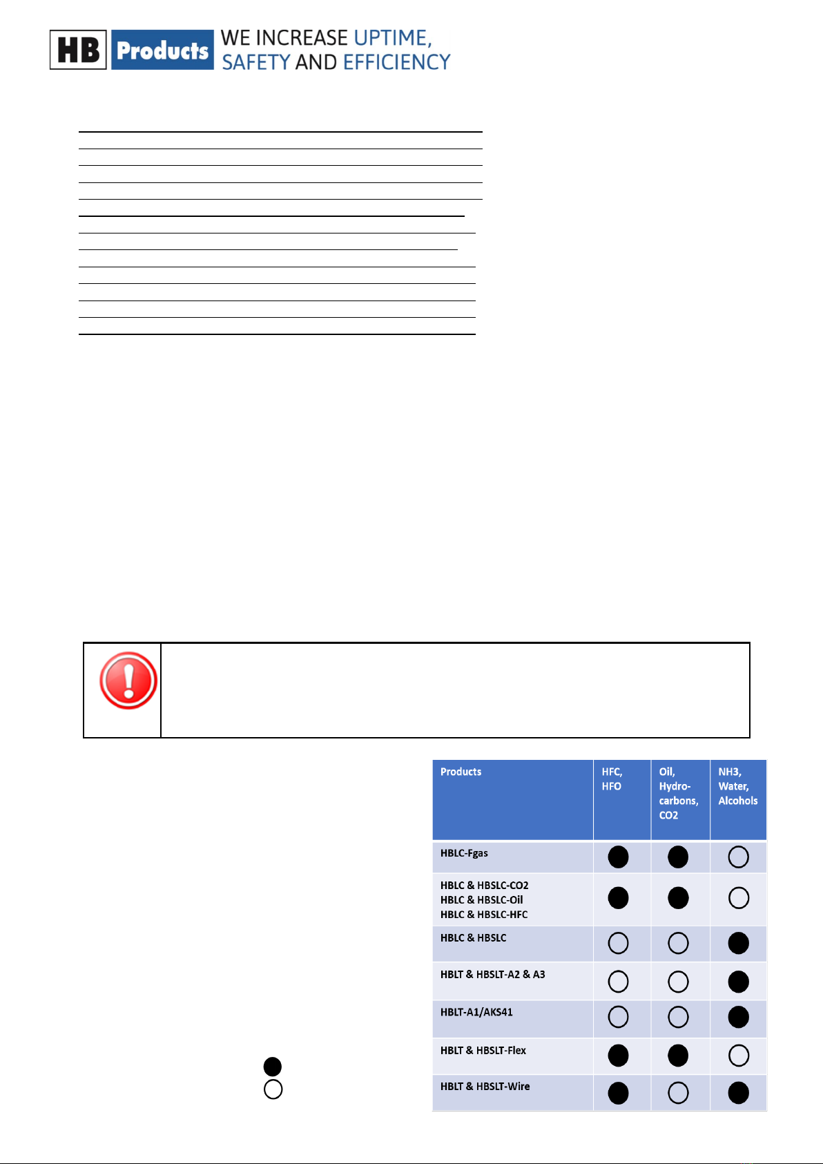
Intended use, condions of use. The level sensor is designed
for connuous measurement of liquids, but please note the
sensor design and setup has to comply with the liquid. The
table show how sensors comply to liquids. It can be used in
refrigeraon systems and similar environments. If the sensor
is to be used in a dierent way and if the operaon of the
product in this funcon is determined to be problemac,
prior approval must be obtained from HB Products.
Prevenon of collateral damage Make sure that qualied
personnel assess any errors and take necessary precauons
before aempng to make replacements or repairs, to avoid
collateral damage.
Disposal instrucons: The sensor is constructed so that the
modules can easily be removed and sorted for disposal.
CAUTION! Refers to a possible limitaon of funconality or risk in usage.
NOTE! Contains important informaon about the product and provides further ps.
The person responsible for operaon must commit to adhering to all the legislave requirements,
prevenng accidents, and doing everything to avoid damage to people and materials.
Comply
Not comply

Wire and Flex level sensor manual 04 October 2021 HBproducts.dk 3
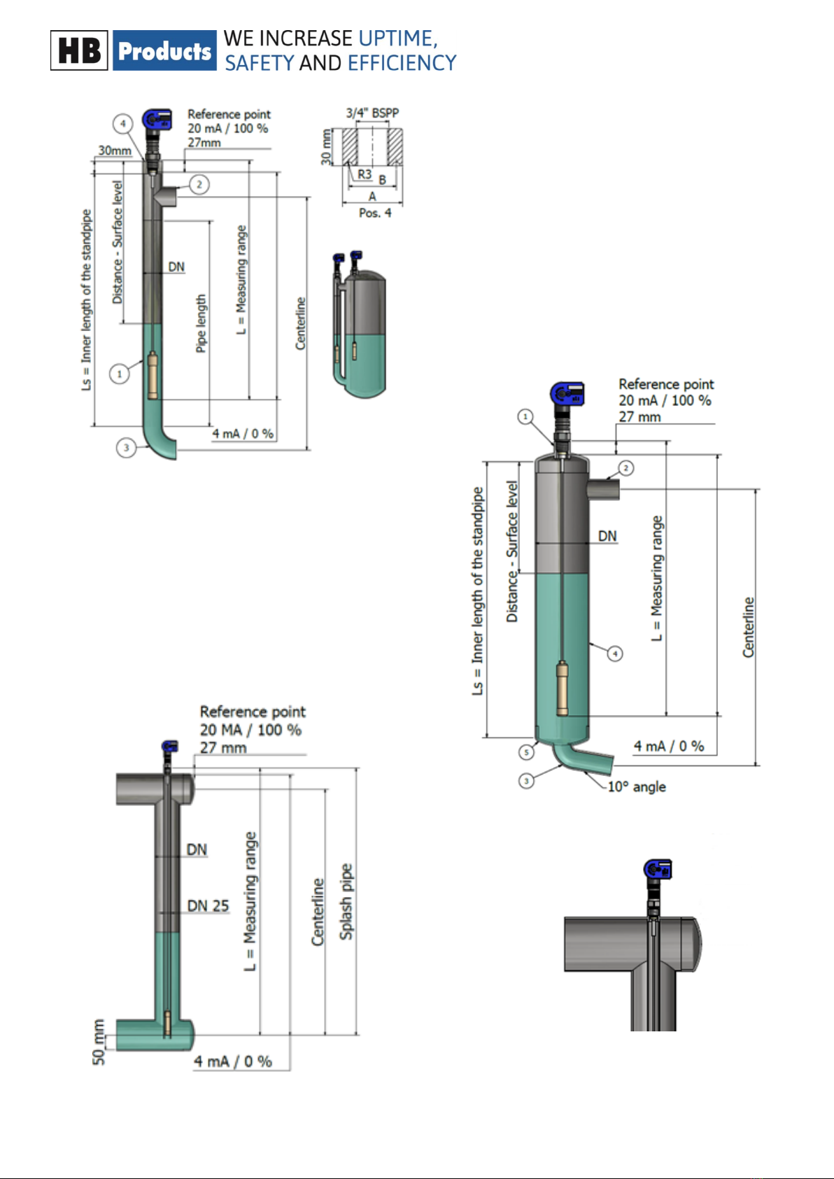
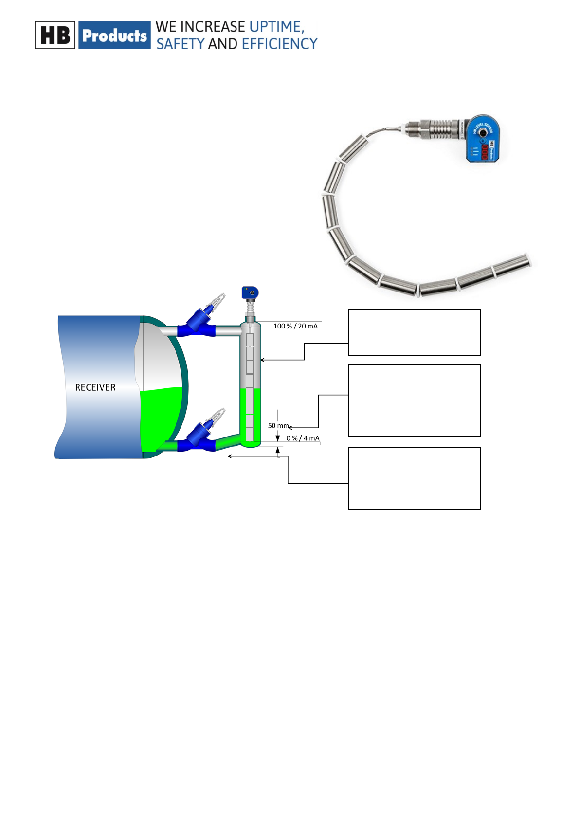
Standpipe should be insula-
ted to avoid boiling in stand-
Drainpipe most be placed at
an angle of 5-10°, to avoid oil
pockets in standpipe.
Sensor must have a minimum
of 50 mm between the sen-
sor weight end and the
boom of the pipe.
The following applies to the design of the system:
• It must be installed in a vercal posion
• Sensor must have a minimum of 50 mm between the sensor weight end and the boom of the pipe.
• The sensor must be installed in an overow or standpipe where the ow stream and turbulence are minimized.
• The sensor must be mounted in a standpipe bigger than DN25. Standpipe must be insulated to avoid boiling of refrig-
erant.
• The outlet pipe from standpipe shall be mounted in an angle of 5-10 degree from horizontal to secure drainage and oil
pockets in refrigeraon systems.
• The sensor is installed and is supplied with a standard non-shielded cable.
If EMC is greater than described in EN 61326, a shielded cable must be used.
The wire sensor is designed for level measurement of liquids in vessels like,
tanks, pump separators and receivers . The sensor can be mounted in a
standpipe from 1” (25mm) up to 4” (100mm) diameter or directly in a vessel
with an inner pipe from 1” (25mm) up to 4” (100mm) diameter. The inner
pipe is needed to create sucient measuring signal and to avoid a swinging
wire in a lively uid. To reduce wire movements in larger pipes a special
weight can be used.
Installaon Instrucons—wire sensor
Special weight for mounng in turbulent
condions. The steel spacer “star” can be
shortened, using a simple n cung shear,
to t the standpipe. Allow 2 mm play be-
tween inner pipe diameter and “star” di-
ameter
Wire and Flex level sensor manual 04 October 2021 HBproducts.dk 4
Stand pipe: DN32..…DN65.
Recommended pipe standard: DIN 10220
Recommended bending: DIN 2615-1/Type 3
Recommended TEE: DIN 2615-1
Standpipe: DN65…DN100.
Recommended pipe standard: DIN 10220
Recommended bending: DIN 2615-1/Type 3
Site pipe can be designed in smaller pipe e.g. o.5 x DN.
Wire and Flex level sensor manual 04 October 2021 HBproducts.dk 5
Standpipe should be insula-
ted to avoid boiling in stand-
Drainpipe most be placed at
an angle of 5-10°, to avoid oil
pockets in standpipe.
Sensor must have a minimum
of 50 mm between the sen-
sor weight end and the
boom of the pipe.
The following applies to the design of the system:
• It must be installed in a vercal posion
• Sensor must have a minimum of 50 mm between the sensor weight end and the boom of the pipe.
• The sensor must be installed in an overow or standpipe where the ow stream and turbulence are minimized.
• The sensor must be mounted in a standpipe DN25 orDN32. The standpipe must be insulated to avoid boiling of refrig-
erant.
• The outlet pipe from standpipe shall be mounted in an angle of 5-10 degree from horizontal to secure drainage and oil
pockets in refrigeraon systems.
• The sensor is supplied and can be is installed with a standard non-shielded cable.
If EMC is greater than described in EN 61326, a shielded cable must be used.
The Flex sensor is designed for level measurement of liquids in
vessels like, tanks, pump separators and receivers . The sensor
can be mounted in a standpipe 1” (25mm) or 1 ¼” (32mm) diam-
eter or directly in a vessel with an inner pipe 1” (25mm) or 1
¼” (32mm) diameter. The inner pipe is needed to create su-
cient measuring signal and to avoid a swinging wire in a lively
uid.
Installaon Instrucons—Flex sensor
This manual suits for next models
9
Table of contents


