HBM M408 User manual

A2400-1.1 en/de
Multiplexer for optical
strain gages
Multiplexer für optische
Dehnungsmessstreifen
M408, M416
Operating Manual
Bedienungsanleitung


3
M408, M416
HBMA2400-1.1 en/de
Contents Page
Safety instructions 4. . . . . . . . . . . . . . . . . . . . . . . . . . . . . . . . . . . . . . . . . . . . .
1 Introduction 10. . . . . . . . . . . . . . . . . . . . . . . . . . . . . . . . . . . . . . . . . . . . . . . . .
1.1 Features 10. . . . . . . . . . . . . . . . . . . . . . . . . . . . . . . . . . . . . . . . . . . . . . . .
1.2 Applications 10. . . . . . . . . . . . . . . . . . . . . . . . . . . . . . . . . . . . . . . . . . . . .
2 Device connections 11. . . . . . . . . . . . . . . . . . . . . . . . . . . . . . . . . . . . . . . . .
2.1 LED displays 11. . . . . . . . . . . . . . . . . . . . . . . . . . . . . . . . . . . . . . . . . . . . .
2.2 Conditions at the place of installation 12. . . . . . . . . . . . . . . . . . . . . . . .
2.3 Maintenance and cleaning 12. . . . . . . . . . . . . . . . . . . . . . . . . . . . . . . . .
3 Connection 14. . . . . . . . . . . . . . . . . . . . . . . . . . . . . . . . . . . . . . . . . . . . . . . . .
3.1 Multiplexer connection to the interrogator 14. . . . . . . . . . . . . . . . . . . .
3.2 Typical optical performance and qualification 16. . . . . . . . . . . . . . . . .
3.3 Remote control interface 16. . . . . . . . . . . . . . . . . . . . . . . . . . . . . . . . . .
3.4 Connecting the sensor chains 16. . . . . . . . . . . . . . . . . . . . . . . . . . . . . .
3.5 PC connection 17. . . . . . . . . . . . . . . . . . . . . . . . . . . . . . . . . . . . . . . . . . .
3.6 Mounting instructions 17. . . . . . . . . . . . . . . . . . . . . . . . . . . . . . . . . . . . .
4 Commissioning the interrogator − multiplexer system 18. . . . . . . . . .
5 Additional settings in catman[Easy/AP 18. . . . . . . . . . . . . . . . . . . . . . .
6 Specifications 20. . . . . . . . . . . . . . . . . . . . . . . . . . . . . . . . . . . . . . . . . . . . . . .
7 Dimensions 21. . . . . . . . . . . . . . . . . . . . . . . . . . . . . . . . . . . . . . . . . . . . . . . . .

4M408, M41
6
HBM A2400-1.1 en/de
Safety instructions
Appropriate use
The multiplexer is to be used exclusively for measurement tasks and directly
related control tasks. Use for any purpose other than the above is deemed to
be inappropriate.
In the interests of safety, the device should only be operated as described in
the Operating Manual. It is also essential to comply with the legal and safety
requirements for the application concerned during use. The same applies to
the use of accessories.
General dangers of failing to follow the safety instructions
The multiplexer corresponds to the state of the art and is failsafe. The device
may give rise to remaining dangers if it is inappropriately installed and
operated by untrained personnel.
Any person instructed to carry out installation, commissioning, maintenance or
repair of the device must have read and understood the Operating Manual
and in particular the technical safety instructions.
Remaining dangers
The scope of supply and performance of the multiplexer covers only a small
area of measurement technology. In addition, equipment planners, installers
and operators should plan, implement and respond to the safety engineering
considerations of measurement technology in such a way as to minimize
remaining dangers. Prevailing regulations must be complied with at all times.
There must be reference to the remaining dangers connected with
measurement technology.
In this Operating Manual, remaining dangers are pointed out using the
following symbols:
Symbol: DANGER
Meaning: Maximum danger level
Warns of an imminently dangerous situation in which failure to comply with
safety requirements will result in death or serious physical injury.

5
M408, M416
HBMA2400-1.1 en/de
Symbol: WARNING
Meaning: Dangerous situation
Warns of a potentially dangerous situation in which failure to comply with
safety requirements can result in death or serious physical injury.
Symbol: CAUTION
Meaning: Possibly dangerous situation
Warns of a potentially dangerous situation in which failure to comply with
safety requirements could lead to damage to property, slight or moderate
physical injury.
Symbols for application and disposal instructions, as well as useful
information:
Symbol: NOTE
Means that important information about the product or its handling is being
given.
Symbol:
Meaning: CE mark
The CE mark enables the manufacturer to guarantee that the product
complies with the requirements of the relevant EC directives (the Declaration
of Conformity can be found at http://www.hbm.com/HBMdoc).
Symbol:
Meaning: Statutory waste disposal mark
In accordance with national and local environmental protection and material
recovery and recycling regulations, old devices that can no longer be used
must be disposed of separately and not with normal household garbage.

6M408, M41
6
HBM A2400-1.1 en/de
If you need more information about waste disposal, please contact your local
authorities or the dealer from whom you purchased the product.
Working safely
Error messages should only be acknowledged once the cause of the error is
removed and no further danger exists.
The device complies with the safety requirements of DIN EN 61010 Part 1
(VDE 0411 Part 1).
Conversions and modifications
The multiplexer must not be modified from the design or safety engineering
point of view except with our express agreement. Any modification shall
exclude all liability on our part for any damage resulting therefrom.
In particular, any repair or soldering work on motherboards is prohibited.
When exchanging complete modules, use only original parts from HBM.
Qualified personnel
This device is only to be installed and used by qualified personnel strictly in
accordance with the specifications and with the safety rules and regulations
listed here. It is also essential to comply with the legal and safety
requirements for the application concerned during use. The same applies to
the use of accessories.
Qualified personnel means persons entrusted with the siting, mounting,
commissioning and operation of the product, who possess the appropriate
qualifications for their function.
WARNING
The multiplexer is a Class A unit. This device can cause radio interference in
living, business and industrial areas. In this case, the operator may be
requested to implement appropriate measures.

7
M408, M416
HBMA2400-1.1 en/de
Key to the safety symbols on the device
The safety symbols shown below are displayed on the device and are
explained in more detail here. These symbols indicate extremely important
information and alert the user to potential risks. Please read carefully through
the safety symbol information and the accompanying explanations. The
device works with laser radiation; to prevent injury never look into the laser
beam and never use optical instruments to look at it. Even the reflection of
laser light from a smooth surface can be harmful. Do not direct the laser beam
onto flammable gas or flammable liquids, as this could cause a fire or an
explosion.
Symbol:
Meaning: Caution − laser!
See explanations in the text
Symbol:
Meaning: Follow the special instructions in the Operating Manual!
Symbol:
Meaning: Caution! Risk from electric current.
Symbol:
Meaning: Housing or chassis, electrically grounded.
Symbol:
Meaning: Risk of electrostatic discharge
Follow the special instructions in the Operating Manual!
Symbol:
Meaning: Protective earth conductor contact for electrical
grounding potential.

8M408, M41
6
HBM A2400-1.1 en/de
Symbol: WARNING
Meaning: Warns of a potentially dangerous situation in which failure to
comply with safety requirements can result in death or serious
physical injury. The user must have read and understood all
instructions before continuing to use.
Symbol: CAUTION
Meaning: Warns of a potentially dangerous situation in which failure to
comply with safety requirements can result in damage to property
or destruction of the device. The user must have read and
understood all instructions before continuing to use.
Laser safety (safety information for the tunable laser frequency generator)
Device specification
Laser type Fiber laser
Laser class 1 (as per IEC 60825-1, 21 CFR 1040.10)
Output power (CW) min > 0.06 mW
max < 0.25 mW
Beam diameter 9 mm
Numerical aperture 0.1
Wavelength See interrogator specifications
NOTE
Should the device malfunction, it must be sent back to HBM for repair.

9
M408, M416
HBMA2400-1.1 en/de
DANGER
Maintenance work must only be carried out by suitably qualified and
authorized personnel. No part of the device may be serviced or maintained by
the user.
Do not activate the laser (do not switch on the device), if an FC/APC plug
is not connected to the optical connecting sockets. For the location of the
optical outputs, see Chapter 2.
The laser is activated when the device is connected to the mains and
initialized. The red LED on the front of the device shows whether the mains
power supply is switched on.
Under no circumstances should you look into the end of an optical fiber
connected to the optical output when the device is in operation.
Laser radiation is not visible to the human eye, but it can seriously damage
your sight.

10 M408, M41
6
HBM A2400-1.1 en/de
1 Introduction
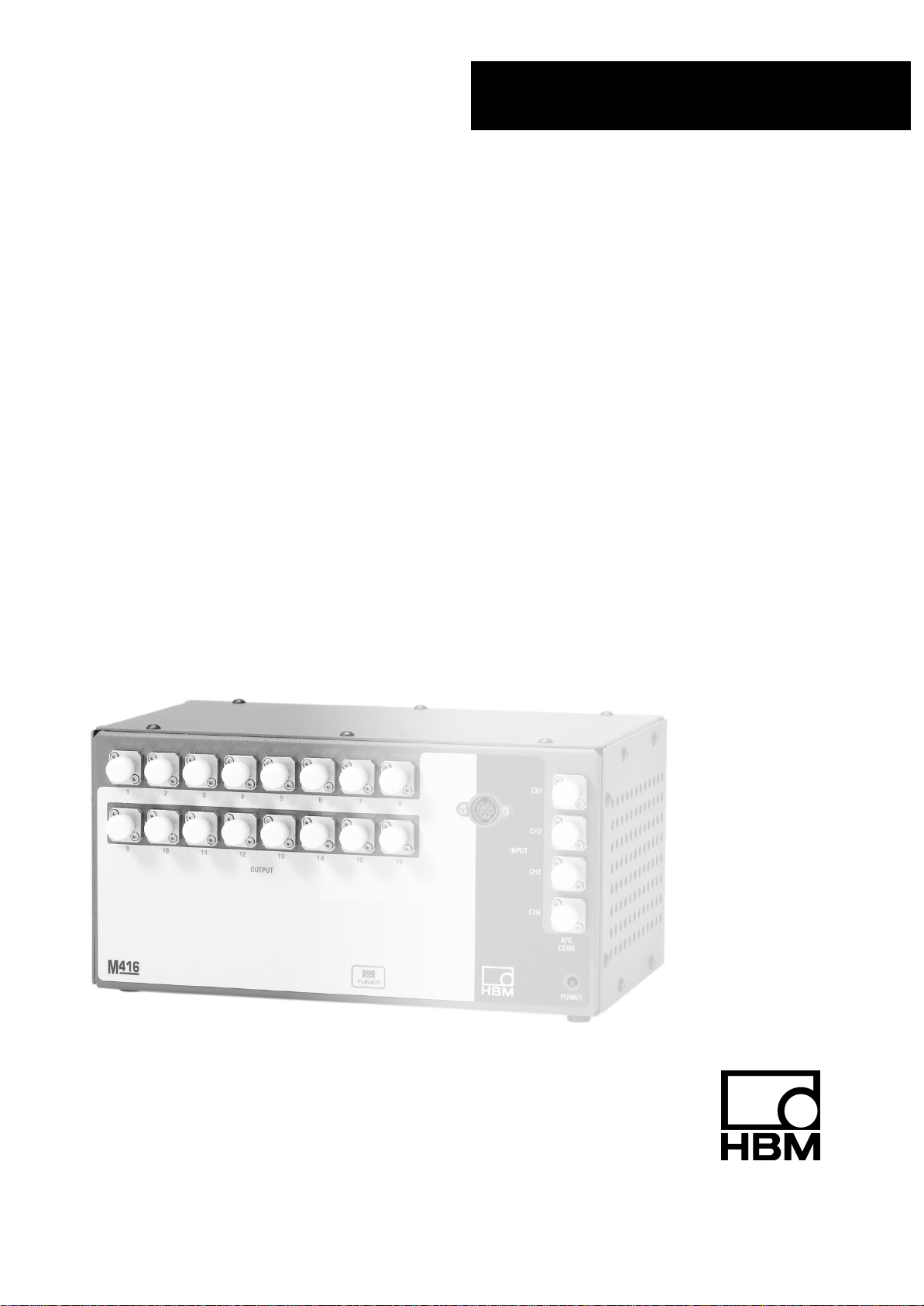
The multiplexers in the HBM series M408, M416 enhance the measuring
capability of the optical interrogators. They consist of a series of highly reliable
high-speed optical switches that are seamlessly integrated in the data
acquisition of the interrogator. The multiplexers can upgrade a four channel
evaluation device to eight or sixteen channel operation while maintaining the
same wavelength accuracy and resolution, and deterministic realtime data
acquisition.
1.1 Features
•Upgrades four channel interrogators to eight or sixteen channel operation
(except SI410 and DI405)
•Realtime data acquisition
•Reliable high-speed optical switching
•Excellent thermal and service life stability
•Seamless integration with associated interrogator
1.2 Applications
•Strain measurements in civil engineering, including bridges, roads and
dams
•Continuous monitoring of structural condition of ships and airplanes
•Underground pressure and temperature measurements in oil bores
•Deep sea oil platform riser monitoring
•Electromagnetically affected environments
•Fields with high energetic potential
•High voltage
•In critical and/or radioactively contaminated areas in chemically aggressive
or corrosive environments
In combination with the optical interrogators in the series SI-.. and DI-, the
system can interrogate up to 208 optical sensors across a 208 nm full range
with a frequency of 0.25 Hz to 500 Hz. The interrogators facilitate the control
of the multiplexer and make the multiplex system data exclusively available
via the Ethernet remote control interface.

11
M408, M416
HBMA2400-1.1 en/de
2 Device connections
3
4
1
2
Fig. 2.1: Front view of the multiplexer for optical SGs
Figure 2.1 shows the front panel of the multiplexer
1) Optical FC/APC input connector(channels 1-4)
2) Optical FC/APC output connector(channels 1-16)
3) Power supply and control connection
4) Power supply display LED.
2.1 LED displays
An LED display is located on the bottom right of the front panel of the M4…
device. This LED shows the status of the multiplexer.
Red LED: ”Ready for operation”
Lights up when the interrogator has been powered up and initialization
performed. This red LED being on tells the user that the connection between
interrogator and multiplexer has been set up and a connection to
catmanEasy/AP and the device can be set up.
Information about the meaning of the LEDs on the interrogator can be found
in the Operating Manuals for the series SI-…or DI-... Chapter 2.1.

12 M408, M41
6
HBM A2400-1.1 en/de
2.2 Conditions at the place of installation
CAUTION
This is an EMC Class A device. It can cause radio interference in home
premises; in this case, the operator may be requested to implement
appropriate measures. Protect the device in a desktop housing from moisture
and dampness or weather conditions such as rain, snow, etc. Make sure that
you do not cover the ventilation openings at the side or the openings
underneath the device. Do not expose the device to direct sunlight.
Comply with the maximum permissible ambient temperatures for the devices, as
stated in the specifications. The permissible relative humidity at 50 °C [122 °F] is
80% (non condensing); linear reduction to 50% at 40 °C [104 °F].
The power pack is intended for use in overvoltage category II. The devices
are only allowed to be operated in a pollution degree rating 2 area, that is,
where normally only non-conductive pollution occurs, with only occasional
temporary conductivity caused by condensation.
2.3 Maintenance and cleaning
The multiplexer is maintenance-free. Please note the following points when
cleaning the housing:
− Before cleaning, disconnect the device from the power supply.
− Clean the housing with a soft, slightly dampened (not wet!) cloth. Never use
solvent as this could damage the labeling on the front panel.
− When cleaning, ensure that no liquid gets into the device or connections.
CAUTION
Do not connect fibers to the device if they have been damaged or are dirty;
this can damage the optical connecting socket on the device.
Never force-fit the optical connector. A sleeve could break off and damage the
device.
Never connect an optical FC/PC or FC/UPC connector to the FC/APC
connection fitted to the front panel of the interrogator. Wrongly assigned
connections of this type can lead to malfunctions or can damage the module.

13
M408, M416
HBMA2400-1.1 en/de
Comply with the usual instructions for cleaning fiber-optics.
1. Fold a lint-free cloth to make a compress.
2. Moisten the compress with isopropyl alcohol.
3. Remove the protective cover of the optical connecting plug.
4. Press the face of the connecting plug firmly onto the moistened part of the
compress and hold it there for a moment. Then wipe the face off by moving it
in a powerful rotary motion towards the edge of the compress. End this
movement in a clean and dry area of the compress. Repeat the process,
making sure that you never use any parts of the compress that are dirty.
5. Dispose of the dirty compress.
NOTE
It is essential that the optical connecting sockets (CH1 − CH16) for the sensor
chains are kept clean. Leave the protective caps on connections that are not
required for measuring mode. Keep the protective caps somewhere safe
when you have connected the optical fibers. When the optical fibers are
disconnected (measuring mode complete), the connecting socket must again
be protected by screwing the protective cap back on.

14 M408, M41
6
HBM A2400-1.1 en/de
3 Connection
3.1 Multiplexer connection to the interrogator
The M4…multiplexers do not have their own power switch. They are switched
on when they are connected to an operational SI-…and DI-…series
interrogator. The power supply can be checked at the multiplexer with the red
LED at the bottom right of the front panel.
The M4…multiplexer has four optical inputs and, depending on the model,
either eight or sixteen optical outputs. The input connectors are arranged
vertically on the right side of the module in the sequence 1 to 4 from top to
bottom. The output connectors are arranged in two horizontal groups of eight
each with the multiplexer channel numbers 1 to 8 in the upper row and 9 to 16
in the lower row (in the case of a 16 channel device).
Each of the four optical inputs of the multiplexer must be connected to the
applicable detector channel on the interrogator. In other words, the physical
detector channel 1 of the interrogator should be connected with an
APC-to-APC bridge to the input channel 1 of the multiplexer. The physical
detector channel 2 of the interrogator should be connected with an
APC-to-APC bridge to the input channel 2 of the multiplexer, channels 3 and 4
in the same manner.
The multiplexer transmits either 2 or 4 channels in one channel to the
interrogator. In this manner, each multiplex channel in the two or four channel
group is transmitted in the same ”physical channel” of the interrogator. The
multiplex channels are grouped as follows into one physical channel:
Multiplex connection in an 8 channel multiplexer:
Multiplex channels Group Interrogator channel
1, 5 1 1
2, 6 22
3, 7 3 3
4, 8 4 4
Multiplex connection in a 16 channel multiplexer:
Multiplex channels Group Interrogator channel
1, 5, 9, 13 1 1
2, 6, 10, 14 2 2
3, 7, 11, 15 3 3
4, 8, 12, 16 4 4

15
M408, M416
HBMA2400-1.1 en/de
Fig. 3.1: Connection diagram of a multiplexer with a 4 channel DI... interrogator

16 M408, M41
6
HBM A2400-1.1 en/de
3.2 Typical optical performance and qualification
Each multiplexer is subject to a complete, automated qualification procedure
to ensure interoperability with the interrogators. Operation is guaranteed
according to interrogator device data, with exception of Chapter 6 in this
Manual, for the combined multiplexer-interrogator system.
3.3 Remote control interface
The entire operation of the multiplexer is simplified by the interrogator. Once
the interrogator is configured for interaction with the multiplexer, the
multiplexer no longer requires operation. All multiplex data generated by the
multiplexer-interrogator combination are exclusively available via the Remote
Ethernet utility of the interrogator. For further information, refer to the
Operating Manuals and data sheets of the applicable interrogators in the
series SI-…and DI-….
3.4 Connecting the sensor chains
The M408 and M416 devices are equipped with optical connector sockets for
8 or 16 optical sensor chains:
1–M408 8 optical sensor chains 8 channels 8 optical connector sockets
1–M416 16 optical sensor chains 16 channels 16 optical connector sockets
These FC/APC sockets are located on the front panel of the multiplexer. Eight
or sixteen outputs are available, depending on the design of the interrogator.
CAUTION
Take exceptional care to ensure that only clean FC/APC sockets are used and
that these are cleaned regularly. Dirty or wrongly adapted sockets reduce the
performance and can cause a great deal of damage to the interrogator. See
Chapter 2.3 ”Maintenance and cleaning”.
WARNING
Under no circumstances should you look into the end of an optical fiber
connected to the optical output when the device is in operation.
Laser radiation is not visible to the human eye, but it can seriously damage
your sight.

17
M408, M416
HBMA2400-1.1 en/de
NOTE
We recommend that you initially connect the device with an optical fiber
approx. 10 − 20 cm in length and connect the actual sensors to. If the sensor
connection gets dirty, the short optical fiber can it be replaced without
damaging the device.
3.5 PC connection
Information about connecting a PC to the interrogator can be found in the
applicable Operating Manuals for the series SI-…or DI-... Chapter 3.4.
3.6 Mounting instructions
The following must be noted when mounting a multiplexer in a control cabinet
or rack:
•Increased ambient temperature – When mounted in a closed or
multi-device rack, the operating ambient temperature in the rack may be
higher than the room temperature (max. 40 °C [104 °F]).
•Reduced air flow - The device should be mounted in the rack in such a
way that the air flow necessary for safe operation is not affected.
•Mechanical strain - Devices should be mounted in the rack in such a
way that no risk of uneven strain can occur.
•Circuit overload – The connection of the devices to the power circuit,
and the effects that a power circuit overload may have on overload
protection and power circuit wiring, must be taken into consideration.
Please comply with the data on the type plate.
•Reliable grounding – Ensure that the devices mounted in the rack are
reliably grounded. Power supply connections that are not directly
connected to the branch line (use of power strips) must be taken into
consideration in particular.

18 M408, M41
6
HBM A2400-1.1 en/de
4 Commissioning the interrogator − multiplexer system
Information about commissioning the interrogator can be found in the
applicable Operating Manual for the series SI-…or DI-... in Chapter 4. Please
connect the multiplexer to the interrogator as described in Chapter 3.
5 Additional settings in catman[Easy/AP
The multiplexer is used to increase the number of interrogator channels. The
settings must be made accordingly in catmanEasy/AP, as described for the
interrogators. The increased number of channels due to the multiplexer must
be set separately in catmanEasy/AP:
•Connect the interrogator with catmanEasy/AP as described in the
Operating Manual for interrogators in model series SI…and DI…in
Chapter 5.1
•Start a ”New measurement project”.
•In the channel settings window, choose the ”Optical sensors −> Analyze
spectrum” menu item.
•In the Analyze spectrum window, select ”Setup”
Fig. 5.1: Setting the number of sensor chains in catman
•In ”Multiplexer – Number of Connectors” activate the number of
channels (8 or 16)

19
M408, M416
HBMA2400-1.1 en/de
•Activate the connection to which the optical sensors are connected, for
example ”CH6”, in the ”Display spectrum for” area.
Fig. 5.2: Setting the parameters for sensor chains 1 − 4
Please note that settings such as Gain and Threshold are only possible with
channels 1 − 4. The settings will be applied for the remaining channels
according to the multiplexer distribution.
8 multiplex channels Group Interrogator
1, 5 1 1
2, 6 2 2
3, 7 3 3
4, 8 4 4
16 multiplex channels Group Interrogator
1, 5, 9, 13 1 1
2, 6, 10, 14 2 2
3, 7, 11, 15 3 3
4, 8, 12, 16 4 4
Table: Allocation of multiplexer sensor chains
One or more signals will then be displayed on the graph, depending on the
strength of the signal and the interrogator settings. Activate ”Autoscaling” if
the signal is not initially visible. If the signal is still not visible after this, check
the optical sensor connection on the device.
The remaining settings in catmaneasy/AP can be found in the Operating
Manual for the interrogators in series SI…or DI…. These are described in
Chapters 5.2 to 5.4.

20 M408, M41
6
HBM A2400-1.1 en/de
6 Specifications
Type M408 M416
Number of input channels 4
Number of output channels 816
Actual spectrum change1) 2 times, through opto−
switch 4 times, through opto−
switch
Relative sampling rate2) 0.5 times 0.25 times
Insertion loss/channel3) dB typ. < 3.0 typ. < 3.0
Dynamic range dB 40 30
Sampling rate 1/s max. 500 max. 250
Optical connector socket FC/APC
Ambient conditions
Nominal temperature range
Ambient humidity range
Storage temperature range
Storage humidity range
°C [°F]
% rel. h.
°C [°F]
% rel. h.
0...+50 [+32...+122]
0...80, non-condensing
−20...+70 [−4...+158]
0...95, non-condensing
Electrical connection values
Supply voltage User-defined interface to the interrogator through
8-pole DIN circular
Weight, approx. kg 1.4
1)Optical switches allow an actual increase of the measurement spectrum available by factor 2 to 4.
2)The optical switches require that the multiplexer acquires data at alternating switch positions. This reduces
the interrogator’s relative sampling rate by a factor equalling the degree of multiplexing. The sampling rate
is maximally reduced by a factor of 2 when using the 8-channel expansion and maximally by a factor of 4
when using the 16-channel expansion module.
3)Insertion loss data apply only for one direction (monomode).
This manual suits for next models
1
Table of contents
Languages: