HC Stage Lighting HC-044 User manual
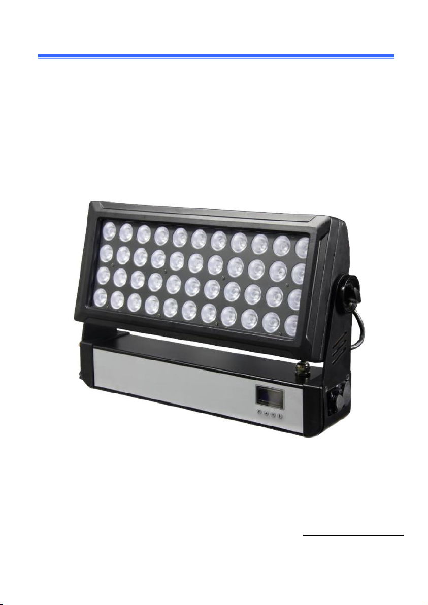
44*10w 4in1 RGBW led wall washer light
User manual
P
le
a
se
rea
d
t
he
ins
t
r
u
ction
s
ca
refu
ll
y before use

2
TABLE OF CONTENTS
1.
S
af
ety
I
nst
r
uctions
.......................................................................................... 2
2. Technical Specifications
............................................................................... 6
3. How To Control The Unit
............................................................................... 7
4. Trouble shooting
........................................................................................... 11
5. Fixture Cleaning
............................................................................................ 12
Statement
The product has well capability and intact packing when leave
factory. All of the user should comply with warning item and manual,
any misuse cause of the damages are not included in our guarantee,
and also cannot be responsible for any malfunction & problem
owing to ignore the manual.
1.
S
af
ety
I
nst
r
uctions
Please keep this User Guide for future consultation. If you sell the unit to
another user, be sure that they also receive this instruction booklet.
Unpack and check carefully there is no transportation damage before using
the unit.
Before operating, ensure that the voltage and frequency of power
supply match the power requirements of the unit.
It’s important to ground the yellow/green conductor to earth in

3
order to avoid electric shock.
The unit must be installed in a location with adequate ventilation,
at least 50cm from adjacent surfaces. Be sure that no ventilation slots are
blocked.
Disconnect main power before replacement or servicing.
Make sure there are no flammable materials close to the unit while
operating as it is fire hazard.
TO Use safety cable when fixing this unit. DO NOT handle the unit by taking
its head only, but always by taking its base.
Maximum ambient temperature is Ta: 40℃. DO NOT operate it where the
temperature is higher than this Unit surface temperature may reach up to
85℃. DO NOT touch the housing bare-hand during its operation. Turn off the
power and allow about 15 minutes for the unit to cool down before replacing
or serving.
In the event of serious operating problem, stop using the unit immediately.
Never try to repair the unit by yourself. Repairs carried out by unskilled
people can lead to damage or malfunction. Please contact the nearest
authorized technical assistance center. Always use the same type spare
parts.
DO NOT touch any wire during operation as high voltage might be causing
electric shock.

4
Warning:
To prevent or reduce the risk of electrical shock or fire do not expose the unit
to rain or moisture.
DO NOT open the unit within five minutes after switching off.
The housing, the lenses, or the ultraviolet filter must be replaced if they are
visibly damaged.
Caution:
There are no user serviceable parts inside the unit. DO NOT open the
housing or attempt any repairs yourself. In the unlikely event your unit may
require service, please contact your nearest dealer.
Dimension
5
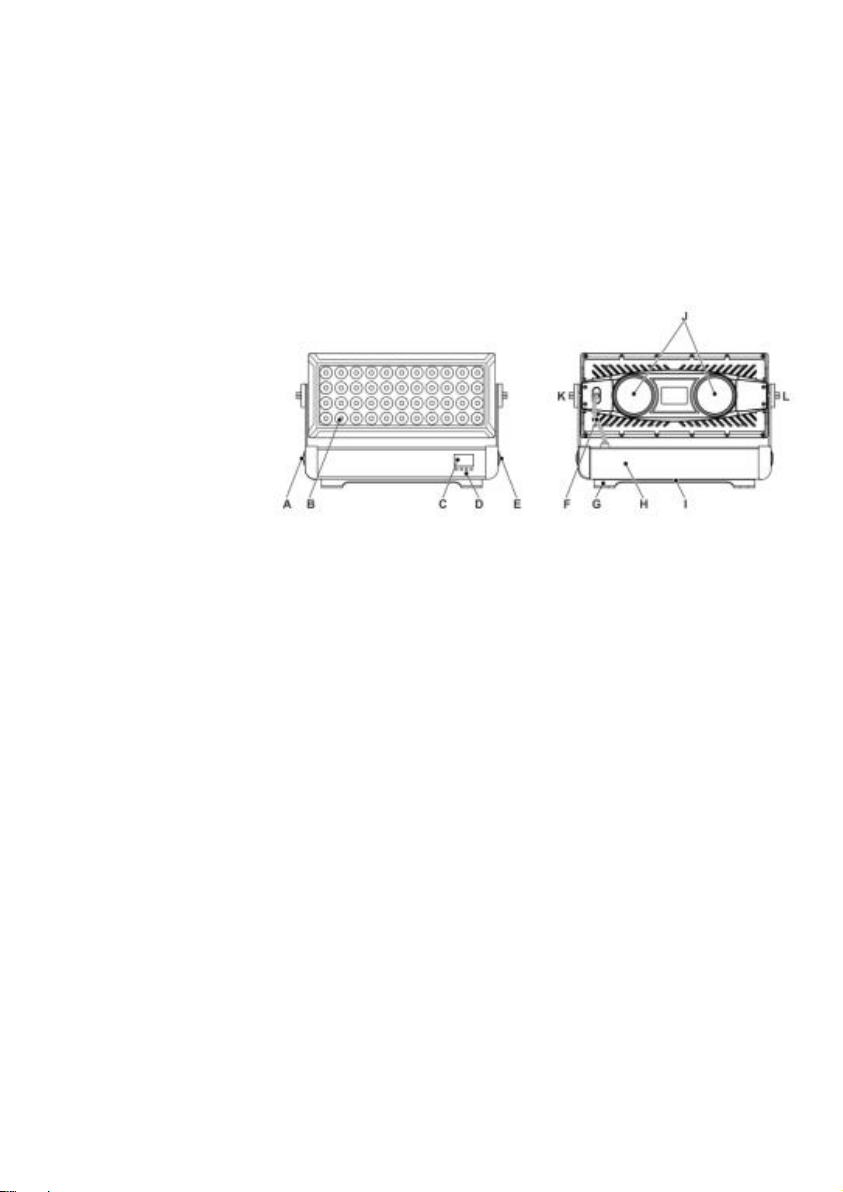
Parts identification and terminology
A Seetronic IP65 sockets
B 44x10w 4in1 leds
C LCD display
D control panel
E Seetronic IP65 sockets
F Connect cables
G Base bracket
H Base
I Safety wire eyelet
J Cooling fans
K Tilt lock
L Tilt lock
Preparing for installation
Unpack the fixture and inspect it to ensure that it has not been damaged during
transport.
The fixture is shipped with two quarter-turn brackets, that can be used to
mount the fixture at elevation.
The fixture is IP55-rated, and is designed for use in wet locations. This means
that it is protected from:
Dust, to the degree that dust cannot enter the fixture in sufficient quantities
as to interfere with its operation.
Lower pressure jets of water from any direction.
When selecting a location for the fixture, ensure that:
It is situated away from public thoroughfares and protected from contact

6
with people.
It is not immersed in water or exposed to high-pressure water jets.
It has adequate ventilation.
Installation:
The unit should be mounted via its screw holes on the bracket. Always ensure
that the unit is firmly fixed to avoid vibration and slipping while
operating. And make sure that the structure to which you are attaching
the unit is secure and is able to support a weight of 10 times of the unit’s
weight. Also always use a safety cable that can hold 12 times of the weight
of the unit when installing the fixture.
The equipment must be fixed by professionals. And it must be fixed at a place
where is out of the touch of people and has no one pass by or under it.
2. Technical Specifications
Light Source:
AC90-24OV,50/60HZ
450W power consumption
44 x high-power 10w RGBW 4in1 leds
Control:
0-100% 32bit linear dimming
1-20 times/second strobe
DMX512,Master-Slave,Auto

7
4/10 DMX channels
4 built in auto mode
6 Dimmer curve
Constructions:
IP65 Rating
Cast aluminum body
2 x two quarter-turn locking points for one or two Omega brackets
Floor stand or hanging rigging possibilities
Bottom mount for safety wire
Forced air cooling system
IP65 Seetronic powercon in and out
IP65 Seetronic dmx in and out
3. How to Control the Unit
The DMX512 is widely used in intelligent lighting control, with a DMX 512
controller. Connect several lights together, dmx in and dmx out,
3 pin XLR connectors: Pin 1: GND, Pin 2: Negative signal (-), Pin 3: Positive
signal (+)

8
Display:
MENU To select the programming functions
DOWN To go backward in the selected functions
UP To go forward in the selected functions
ENTER To confirm the selected functions
Set
DMX
Address Code
1 Press "Menu" to "Set DMX Address", and press "ENTER" keys to
enter into
2 Show "Set DMX Address DMX Address: 001", Press the "UP and
DOWN" keys to amended
3 Press "ENTER “keys to save and Exit, Press the "MENU" Keys does
not save and

9
Level 1
Level 2
Description
Address
001-512
DMX address setting
Mode
4 CH DMX
4 channels mode
10 CH DMX
10 channels mode
Auto 1 ( 001-099 )
Color change mode,speed adjustable
Auto 2 ( 001-099 )
Color fade mode, speed adjustable
Auto 3 ( 001-099 )
Color pulse mode,speed adjustable
Auto 4
Color macro mixed
Adjust
RED
Red color manual dimmer
GREEN
Green color manual dimmer
BLUE
Blue color manual dimmer
WHITE
White color manual dimmer
CURVE
Dimmer curve reference to CH9
TEMP
Fixture temperature display
DMX protocols
Configuring DMX is described “Setting the DMX mode” on page 11.
Channel
Value
Function
4CH
10CH
1
1
Red :
0-255
Red dimmer
2
2
Green :
0-255
Green dimmer

10
3
3
Blue :
0-255
Blue dimmer
4
4
White :
0-255
White dimmer
*
5
Dimmer :
0-255
All dimmer
*
6
Strobe :
0-9
No function
10-255
Strobe
*
7
Auto Macro :
0-9
No function
10-50
Color change macro
51-100
Color fade macro
101-150
Color pulse macro
201-255
No function
*
8
Auto Marco Speed:
0-255
Speed from slow to fast
*
9
Dimmer Curve:
0-9
Dimmer curve set by menu
10-50
Dimmer curve 1
51-101
Dimmer curve 2
102-152
Dimmer curve 3
153-203
Dimmer curve 4
204-249
Dimmer curve 5
250-255
Dimmer curve 6
*
10
0-255
Color temperature ( Warm to Cool )

11
4. Trouble shooting
F
ollo
w
ing
a
r
e
a
few
c
o
mm
on
p
r
oble
m
s
th
a
t
m
a
y occu
r
d
uring
ope
r
a
tion
. He
r
e
a
r
e
s
o
m
e
s
ug
ges
tion
s
fo
r
eas
y
tr
ou
b
leshooting
:
A. The
un
it
does
no
t
work
, no
li
ght
a
n
d
t
he
f
a
n
d
o
es
no
t
w
o
r
k
1.
Check
th
e
c
on
nect
ion of p
owe
r
a
nd
m
a
in
fu
s
e
.
2.
M
eas
ure
th
e
m
a
ins
volt
a
ge
on
th
e
m
a
i
n
co
nn
e
ct
o
r
.
3.
Check
th
e
pow
er
on
LED
.
B.
N
o
t
responding
t
o
D
MX
c
on
t
ro
ll
er
1.
DMX LED should be on. If not, check DMX connectors, cables to see if link
properly.
2.
If the DMX LED is on and no response to the channel, check the address
settings and DMX polarity.
3.
If you have intermittent DMX signal problems, check the pins on connectors or
on PCB of the unit or the previous one.
4.
Try to use another DMX controller.
5.
Check if the DMX cables run near or run alongside to high voltage cables that
may cause damage or interference to DMX interface circuit.

12
5. Fixture Cleaning
T
he cleaning of internal and external optical lenses and/or mirrors must be
carried out periodically to optimize light output. Cleaning frequency depends
on the environment in which the fixture operates: damp, smoky or particularly
dirty surrounding can cause greater accumulation of dirt on the unit’s optics.
Clean it with soft cloth using normal glass cleaning fluid.
always dry the parts carefully.
Clean the external optics at least every 20 days. Clean the internal optics
a
t
lea
s
t
ev
ery
30/60
days.
Table of contents
Other HC Stage Lighting Lighting Equipment manuals

Popular Lighting Equipment manuals by other brands


SCHOTT
SCHOTT VisiLEDs MC Series operating instructions

Chroma
Chroma Space Force onebytwo LumenRadio Card installation guide

American DJ
American DJ ScanTron 250 User instructions

WE-EF
WE-EF QSI254 Installation and maintenance instructions

Durite
Durite 0-441-80 instructions

American DJ
American DJ P64 LED User instructions


