HC Stage Lighting HC-015F User manual
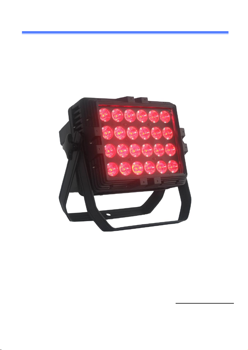
HC-015F
24*12w 6in1 RGBWA+UV led par
User manual
P
le
a
se
rea
d
t
he
ins
t
r
u
ction
s ca
refu
ll
y before use

2
TABLE OF CONTENTS
1.
S
af
ety
I
nst
r
uctions
....................................................................................2
2. Technical Specifications
.......................................................................... 4
3. How To Control The Unit
........................................................................5
4. Trouble shooting
.................................................................................... 10
5. Fixture Cleaning
.....................................................................................11
Statement
The product has well capability and intact packing when leave
factory. All of the user should comply with warning item and manual, any
misuse cause of the damages are not included in our guarantee, and
also cannot be responsible for any malfunction & problem owing to
ignore the manual.
1.
S
af
ety
I
nst
r
uctions
Please keep this User Guide for future consultation. If you sell the unit to another
user, be sure that they also receive this instruction booklet.
Unpack and check carefully there is no transportation damage before using
the unit.
Before operating, ensure that the voltage and frequency of power
supply match the power requirements of the unit.
It’s important to ground the yellow/green conductor to earth in order
to avoid electric shock.

3
The unit must be installed in a location with adequate ventilation, at
least 50cm from adjacent surfaces. Be sure that no ventilation slots are
blocked.
Disconnect main power before replacement or servicing.
Make sure there are no flammable materials close to the unit while operating as
it is fire hazard.
TO Use safety cable when fixing this unit. DO NOT handle the unit by taking its
head only, but always by taking its base.
Maximum ambient temperature is Ta: 40℃. DO NOT operate it where the
temperature is higher than this Unit surface temperature may reach up to 85℃.
DO NOT touch the housing bare-hand during its operation. Turn off the power
and allow about 15 minutes for the unit to cool down before replacing or serving.
In the event of serious operating problem, stop using the unit immediately.
Never try to repair the unit by yourself. Repairs carried out by unskilled
people can lead to damage or malfunction. Please contact the nearest
authorized technical assistance center. Always use the same type spare
parts.
DO NOT touch any wire during operation as high voltage might be causing
electric shock.
Warning:
To prevent or reduce the risk of electrical shock or fire do not expose the unit to
rain or moisture.
DO NOT open the unit within five minutes after switching off.
The housing, the lenses, or the ultraviolet filter must be replaced if they are

4
visibly damaged.
Caution:
There are no user serviceable parts inside the unit. DO NOT open the housing
or attempt any repairs yourself. In the unlikely event your unit may require
service, please contact your nearest dealer.
Installation:
The unit should be mounted via its screw holes on the bracket. Always ensure that
the unit is firmly fixed to avoid vibration and slipping while operating.
And make sure that the structure to which you are attaching the unit is secure
and is able to support a weight of 10 times of the unit’s weight. Also always use a
safety cable that can hold 12 times of the weight of the unit when installing the
fixture.
The equipment must be fixed by professionals. And it must be fixed at a place
where is out of the touch of people and has no one pass by or under it.
2. Technical Specifications
Light Sources: 24pcs RGBWA+UV 6 in 1 LED
Power Consumption: 300W
Power Voltage: AC 100-220V, 50/60Hz
Gross Weight: 10Kgs
Control
DMX Channel: 7/11Channel
Control Modes: DMX/auto run/master slave

5
Construction
Display: Digital panel
Data In/Out socket: 3-pin
IP rate:IP65
Features
Dimming:32bit
Refresh rate:20K HZ
Flicker free in camera,TV
Perfect dimmer curve
Best color mixing effect
3. How to Control the Unit
Th
e
D
M
X512 is
w
id
ely
used
in
intellig
ent
ligh
ti
ng
co
n
tr
ol, with a DMX 512
controller. Connect several lights together, dmx in and dmx out,
3
p
in
XLR
co
nn
ectors
:
Pin
1:
G
ND
,
Pin
2:
Nega
tive
s
ig
n
a
l
(-),
Pin
3:
P
o
s
itive
s
i
gna
l
(+)
6
Display:
MENU To select the programming functions
DOWN To go backward in the selected functions
UP To go forward in the selected functions
ENTER To confirm the selected functions
Set DM X
Address Code
1 Press "Menu" to "Set DMX Address", and press "ENTER" keys to enter into
2 Show "Set DMX Address DMX Address: 001", Press the "UP and DOWN"
keys to amended
3Press "ENTER “keys to save and Exit, Press the "MENU" Keys does not save
and
LED Display Function Table
No.
Display
Function
1
d001
7 channel address code, (001-512)
B, C key to add and subtract address
code values
2
d.001
11 Channel address code, (001-512)
B, C key to add and subtract address
code values
3
CC01
colour jump to change, (01-99)
B, C key to modify jump to change
speed
4
CP01
Gradient (01-99)
B, C key to modify the colors

7
5
dE01
colour pulse variable, (01-99)
B and C modify pulse variable,
velocity gradient
6
dENo
Jump, Gradient and pulse variable
7
bEbE
Sound control,Jump,Gradient and
pulse variable
8
R255
Red colors, (000-255)
B, C key to modify the colors
9
G255
Green colors, (000-255)
B, C key to modify the colors
10
B255
Blue colors, (000-255)
B, C key to modify the colors
11
W255
White colors, (000-255)
B, C key to modify the colors
12
A255
Amber colors, (000-255)
B, C key to modify the colors
13
UV255
UV colors, (000-255)
B, C key to modify the colors
14
Dr01
Dr02
Dr03
Dr04
Dr05
Mode 1 Linear dimmer
Mode 2 Quickly turn on or turn off
Mode 3 Slow speed of linear dimmer
Mode 4 More slower linear dimmer
Mode 5 More slower speed of linear
dimmer
8
DMX512 7 Channel
Channels
Function
DMX512
Value
Details
CH1
Red
0-255
R dimmer, linear, dark
→bright (0-100%)
CH2
Green
0-255
G dimmer, linear, dark
→bright (0-100%)
CH3
Blue
0-255
B dimmer, linear, dark
→bright (0-100%)
CH4
White
0-255
W dimmer, linear, dark
→bright (0-100%)
CH5
Amber
0-255
A dimmer, linear, dark
→bright (0-100%)
CH6
UV
0-255
UV dimmer, linear, dark
→bright (0-100%)
CH7
Dimmer
mode
selection
0-9
Display board menu
functions
10-50
Linear dimmer
51-101
Quickly turn on or turn off
102-152
Slow speed of linear dimmer
153-203
More slower linear dimmer
204-255
More slower speed of linear
dimmer

9
DMX512 11 Channel
Channels
Function
DMX512
Value
Details
CH1
Red
000-255
R adjustment, linear,
dark →bright (0-100%)
CH2
Green
000-255
G adjustment, linear,
dark →bright (0-100%)
CH3
Blue
000-255
B adjustment, linear,
dark →bright (0-100%)
CH4
White
000-255
W adjustment, linear,
dark →bright (0-100%)
CH5
Amber
000-255
A adjustment, linear,
dark →bright (0-100%)
CH6
UV
000-255
UV adjustment, linear,
dark →bright (0-100%)
CH7
Dimmer
mode
selection
0-9
Display board menu
functions
10-50
Linear dimmer
51-101
Quickly turn on or turn off
102-152
Slow speed of linear
dimmer
153-203
More slower linear
dimmer
204-255
More slower speed of
linear dimmer
CH8
Dimmer
000-255
All dimmer for

10
RGBWA+UV (0-100%)
CH9
Strobe
000-255
R, G, B, W,A,UV strobe,
slow →fast
CH10
Function
Choose
10-50
Jump effect
51-100
Gradual change
101-150
Pulse variable effect
151-200
Jump, gradual and pulse
variable effect
201-255
Sound control
CH11
Speed
000-255
Function Speed, slow
→fast
4. Trouble shooting
F
ollo
w
ing
a
r
e
a
few
c
o
mm
on
p
r
oble
m
s
th
a
t
m
a
y occu
r
d
uring
ope
r
a
tion
. He
r
e
a
r
e
s
o
m
e
s
ug
g
es
tion
s
fo
r
ea
s
y
tr
ou
b
leshooting
:
A.
The
un
it
does
no
t
work
, no
li
ght
a
n
d
t
he
f
a
n
d
o
es
no
t
w
o
r
k
1.
Ch
eck
th
e
c
on
nect
ion of
p
owe
r
a
nd
m
a
in
fu
s
e
.
2.
M
eas
ure
th
e
m
a
ins
volt
a
g
e
on
th
e
m
a
i
n
co
nn
e
ct
o
r
.
3.
Ch
eck
th
e
pow
er
on
LED
.
B.
N
o
t
responding
t
o
D
MX
c
on
t
ro
ll
er
1.
DMX LED should be on. If not, check DMX connectors, cables to see if link
properly.

11
2.
If the DMX LED is on and no response to the channel, check the address
settings and DMX polarity.
3.
If you have intermittent DMX signal problems, check the pins on connectors or on
PCB of the unit or the previous one.
4.
Try to use another DMX controller.
5.
Check if the DMX cables run near or run alongside to high voltage cables that
may cause damage or interference to DMX interface circuit.
5. Fixture Cleaning
Th
e
clean
ing
o
f
inter
na
l
a
nd
ex
ter
na
l
optica
l
lens
es
a
nd/or
m
ir
r
ors
m
u
s
t
b
e
c
a
rr
ied
out periodically to optimize light output. Cleaning frequency depends on the
environment in which the fixture operates: damp, smoky or particularly dirty
surrounding can cause greater accumulation of dirt on the unit’s optics.
Cle
a
n
it
with
s
oft
clo
th
u
s
ing
no
r
m
a
l
g
l
a
ss
clea
ni
ng
fluid
.
always
d
r
y
th
e
parts
ca
r
ef
ully
.
Cle
a
n
th
e
ex
ter
na
l
optic
s
a
t
leas
t
ev
ery
20
days. Cle
a
n
th
e
in
ter
na
l
opti
cs
a
t
lea
s
t
ev
ery
30/60
days.

12
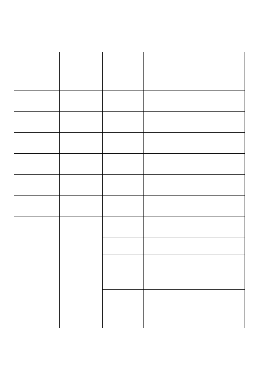
Parts List
Name
Picture
Quantity
Power cable
European/British
standard/American
Standard,etc. Can choose
One
XLR cable in&out
One set
Waterproof cap for DMX
cable and power cable
One set
Table of contents
Other HC Stage Lighting Lighting Equipment manuals

Popular Lighting Equipment manuals by other brands

Lightolier
Lightolier Lytespan 6190 specification

Robe
Robe Anolis Eminere Classic 12 user manual

Uplus Lighting
Uplus Lighting 460LED BSW user manual

RHINO
RHINO XPLOR Blackout Series installation instructions

Vision & Control
Vision & Control Vicolux R-CLR-38x20-B465-SL Installation and operating instructions

ALUZ
ALUZ A8-ZIZA-TAPE installation instructions


