HD Electric VarCom 1600 Instruction Manual

VarCom®1600
VarCom
®
C mmunicati ns Ready
C A P A C I T O R C O N T R O L S
Model 1600 & 2600
Operating & Instruction Manual
VarCom®2600
1475 Lakeside Drive • Waukegan, Illinois 60085 U.S.A. • 847.473.4980
fax 847.473.4981 • website: www.HDElectricCompany.com

2
Overview ............................................................................... 3
Installation .............................................................................. 4
Current Sensor ............................................................................4
Fusing .................................................................................. 5
Manual Operation ....................................................................... 5-6
Programming for Automatic Operation....................................................... 6-15
Settings Common to All Models ............................................................ 6
Setting the Control Mode ................................................................. 7
Schedule Settings .................................................................... 7-10
Other Settings ...................................................................... 10-11
Voltage Settings ..................................................................... 10
Temperature Settings ................................................................. 10
KVAR Settings ......................................................................... 11
Reverse Power Set ................................................................... 11
System Monitoring ..................................................................... 12
Neutral Current Monitoring............................................................... 13
Clock Back-Up Battery ..................................................................... 13
LED Indicators ........................................................................... 14
LCD Display ............................................................................. 15
Specifications ......................................................................... 16-17
VarWare Programming and Data Analysis Software .............................................18-22
Software Installation .................................................................... 19
Using the Software for the First Time ........................................................ 19
Create a Control Program .............................................................. 19-20
Upload a Setup Program to a VarCom Control ................................................. 20
Use Profile Data Logging .............................................................. 20-21
View and raph Downloaded Profile Data ................................................. 21-22
Real Time Monitoring of the VarCom Capacitor Control .......................................... 22
Limitation of Warranty and Liability ........................................................... 24
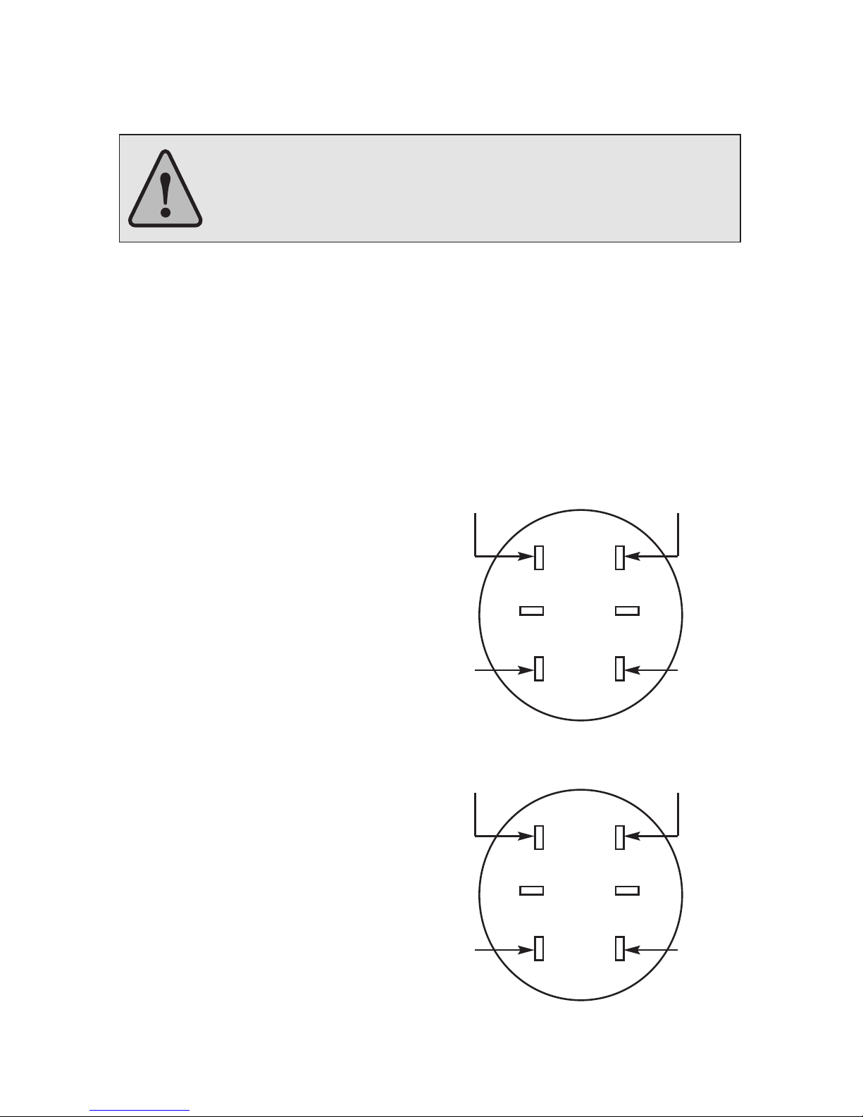
WARNING: Prior to installing, operating, maintaining or testing this equipment, read and understand the
material in this manual. Failure to comply can result in death, severe injury and equipment damage. These
instructions are intended to supplement, not replace, local safety practices and procedures.
VarCom Capacitor Controls set the standard for ease of use by providing sophisticated control and
monitoring capabilities in an intuitive easy to use package. VarWare Windows™ compatible software
extends these capabilities.
Please visit our website for the latest information on these and other quality HD Electric Company products.
www.HDElectricCompany.com
VarCom
®
C mmunicati ns Ready
C A P A C I T O R C O N T R O L S
Model 1600 & 2600

3
OVERVIEW
The VarCom 1600 and 2600 Capacitor Controls utilize user selectable functions and
parameters to control switched capacitor banks. The VarCom 1600 controls with time,
temperature and voltage and the VarCom 2600 add Amps and KVAR control.
TIME - The Control will close the capacitor bank when the user selected CLOSE TIME occurs.
The Control will open the capacitor bank when the user selected OPEN TIME occurs. Both
settings are subject to the weekend settings.
OLTAGE - The Control will close the capacitor bank when the sensed line voltage drops
below the user selected CLOSE VOLTS setting. The Control will open the capacitor bank
when the sensed line voltage rises above the user selected OPEN VOLTS setting.
TIME WITH OLTAGE O ERRIDE - The Control will function according to the time mode,
except the time mode operating conditions will be overridden by voltage conditions
according to the volt mode function.
TEMPERATURE - For Summer Schedule (defined by CLOSE TEMP greater than OPEN TEMP
setting) - the Control will close the capacitor bank when the sensed ambient temperature
rises above the user selected CLOSE TEMP setting. The Control will open the capacitor bank
when the sensed ambient temperature drops below the user selected OPEN TEMP setting.
For Winter Schedule (defined by OPEN TEMP greater than CLOSE TEMP setting) - the Control
will close the capacitor bank when the sensed ambient temperature drops below the user
selected CLOSE TEMP setting. The Control will open the capacitor bank when the sensed
ambient temperature rises above the user selected OPEN TEMP setting.
TIME WITH TEMPERATURE O ERRIDE - The Control will function according to the time
mode, except the time mode operating conditions will be overridden by temperature
conditions according to the temp mode function.
TEMPERATURE WITH OLTAGE O ERRIDE - The Control will function according to the
temp mode, except the temp mode operating conditions will be overridden by voltage
conditions according to the volt mode function.
TIME WITH OLTAGE AND TEMPERATURE O ERRIDE - The Control will function according
to the time mode, except the time mode operating conditions will be overridden by
temperature conditions according to the temp mode function and/or by voltage conditions
according to the volt mode function. Voltage will override both time and temperature.
AMPS - The control will close the capacitor bank when the line amps drop below the user
selected Amps setting. The control will open the capacitor bank when the line amps rise
above the user selected Amps setting.
AMPS WITH OLTAGE O ERRIDE - The Control will function according to the Amps
settings, except the Amps setting operating conditions will be overridden by voltage
conditions according to the volt mode function.
K AR - The Control will close the capacitor bank when the line KVAR rises above the user
selected KVAR setting. The Control will open the capacitor bank when the line KVAR drops
below the user selected KVAR setting.
K AR WITH OLTAGE O ERRIDE - The Control will function according to the KVAR
settings, except the KVAR setting operating conditions will be overridden by voltage
conditions according to the volt mode function.
4
INSTALLATION
All VarCom Controls are supplied ready for 4 or 6 jaw meter socket mounting or for
mounting directly to a pole with a supplied mounting bracket.
WARNING: Before plugging the Control into a live meter socket, rotate
the main switch out of the AUTO position or remove the front panel fuse,
and observe all safety procedures for working with exposed live circuits.
Failure to comply can result in death, personal injury or equipment damage.
INSTALLING INTO A RINGED BASE
Align the terminals on the back of the Control and press firmly into the meter socket.
Use the supplied ring to complete the installation. Attach a ground wire to the external
ground lug. Seal or lock the ring only after the entire system has been verified.
INSTALLING POLE MOUNTED CONTROLS
Pole Mounted Controls are mounted with the included pole bracket and user supplied
mounting straps or lag screws. After the Control is attached to the pole, attach a ground
wire to the external ground lug.
WIRING INSTALLATION:
Use the following wiring diagram
for installing a VarCom control:
Note that the line current sensor connections
are polarity sensitive. A control indication of
reverse power flow can often be corrected by
reversing the black and white leads from the
line current sensor from those shown
in this diagram.
CURRENT SENSOR
The VarCom 2600 Control is supplied ready
to operate with Lindsey™ CVMI or Fisher
Pierce™ 1301 overhead current sensors,
which can be purchased separately. The
sensor output must be 600A: 10V. If the
current sensor is connected to a phase
different than the Control supply voltage,
refer to the software section of this
manual (beginning on pg 18)
to make phase adjustments.
Voltage sensing for the Control is pre-wired
to use the supply voltage, typically 120 or 240V.
Please consult the factory for other configurations.
Neutral
SERIES 1600 CONTROLS
Line 120V AC
Open Close
Neutral Sensor
Neutral Sensor
12
56
4
3
Neutral: Line sensor (White),
and Neutral sensor (White)
SERIES 2600 CONTROLS
Line 120V AC
Open Close
Line Sensor (Black)
Neutral Sensor (Black)
12
56
4
3
5
FUSIN
All VarCom Controls are supplied with a 15 Amp SLO-BLO® fuse, accessible from the front
panel. This fuse protects the capacitor bank switches. If it was removed before installation,
the fuse should be reinstalled after installation is complete.
An internal fuse that is not field replaceable protects the Control circuitry.
All repairs should be referred to the factory.
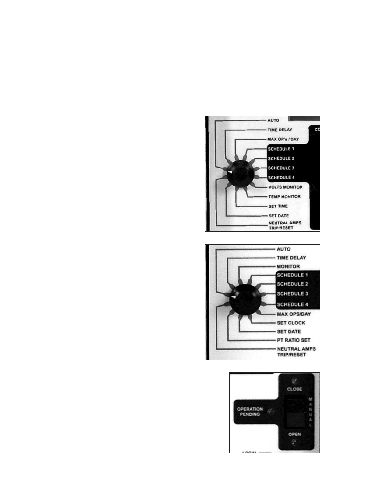
MANUAL OPERATION
All VarCom Controls can be used to operate
the connected capacitor bank switches
manually. To manually CLOSE or OPEN
the capacitor bank using the Control
front panel rocker switch:
1) Switch the Control out of the AUTO
mode, verify that the red lamp is off,
and select TIME DELAY. Using the
ADJUST knob, select the desired time
delay, in seconds, from 3 to 600. This
will delay both manual and automatic
operations by the time selected. The
OPERATION PENDIN light flashes
before every open or close operation
during the time delay period.
2) Use the MANUAL rocker switch to OPEN
or CLOSE the capacitor bank switches.
The OPERATION PENDIN light will flash
for the duration of the selected TIME
DELAY. When the output is energized, the
CLOSE or OPEN light will flash. Then, the
output will de-energize and the
light will remain on.
The capacit r bank cann t perf rm a
cl se perati n less than 5 minutes after
a trip perati n t all w time f r the
capacit rs t discharge. If a CLOSE
perati n is attempted during this
5 minute time peri d, the C ntr l will
display 5MIN DLY and the C ntr l
will n t cl se the bank.
Series 1600 Controls
Series 2600 Controls

6
NOTE: Manual operations are counted by the operations counter (close operations
only), but manual operations do not count against the preset daily limit set by MAX
OPS/DAY.
After completing the required manual operations, return the Control to AUTO
for automatic operation. The AUTO light confirms Automatic operation.
NOTE: Pending manual operations can be canceled by turning the Control to
AUTO. Similarly, pending automatic operations can be canceled by switching out
of AUTO to any other switch position.
PRO RAMMIN FOR
AUTOMATIC OPERATION
Programming and set-up information
for VarCom Controls.
Settings Common to all Models
AUTO is the normal automatic operating
mode for the Control. The display shows
the operations counter, which cannot
be reset. The operations counter counts
all CLOSE operations.
TIME DELAY sets the time delay, in seconds,
for both manual and automatic operations.
The delay can be set from 3 to 600 seconds
in 3 second increments using the ADJUST
switch. The OPERATION PENDIN light
flashes before every open or close operation
during the entire time delay period.
MAX OP’S/DAY sets the maximum number of
automatic capacitor bank CLOSE operations
per rolling 24-hour period. This can be set
from 2 to 24 operations using the ADJUST
switch. This setting overrides all other time,
temperature, current or voltage settings. If the
daily operations limit is reached, the display
will alternately show the operations counter
and OP LIMIT while the Control is in AUTO
mode. When MAX OPS is reached, the last
operation will be an OPEN. Manual
operations do not count against the
limit set by MAX OPS/DAY.
Series 1600 Controls
Series 2600 Controls

7
SETTIN THE CONTROL MODE
The Model 1600 Control can allow voltage and/or temperature to override time settings.
The Model 2600 Control can allow voltage to override temperature, time, amp and
KVAR settings. Depending on the model, the following Control Modes can be used:
C ntr l Display
M de Sh ws
Time only TIME
Time with voltage override VOLT/TIM
Voltage only VOLT
Time with temperature override TMP/TIME
Temperature only TEMP
Temperature with voltage override VOLT/TMP
Time with voltage and V/TMP/TI
temperature override
Amps LINE AMPS
Amps with voltage override LINEAMP/V
KVAR KVAR
KVAR with voltage override KVAR/VOLT
SCHEDULE SETTIN S
Four independent time schedules are available - SCHEDULE 1 through SCHEDULE 4.
Each time schedule allows one OPEN and one CLOSE operation per day. The schedules
can be used to set multiple OPEN and CLOSE operations for each day or they can be
used for seasonal changes to the schedule, e.g. different OPEN and CLOSE times for
summer and winter.
For each schedule selected, week days MON-FRI, weekend days SAT and SUN, and
HOLIDAYS can be selected to be ACTIVE or OFF. ACTIVE days will follow the TIME ON
and TIME OFF settings as well as any temperature or voltage override settings. OFF
days will cause the capacitor bank to remain open.
The six standard holidays are New Years Day, Memorial Day, July 4th, Labor Day,
Thanksgiving Day and Christmas Day. The VarCom Controls allow a maximum of ten
holidays to be programmed.
Series 2600 Controls

8
EXAMPLE 1 - SEASONAL ARIATION - Two time schedules are used for seasonal variation
in the OPEN and CLOSE times and/or override settings (if any). TIME SCHEDULE 1 is a
summer schedule with a START DATE of 4/1, a STOP DATE of 9/30, TIME ON at 07:00
and TIME OFF at 18:00 (all time settings are in 24 hour format). TIME SCHEDULE 2 is a
winter schedule with a START DATE of 10/1, a STOP DATE of 3/31, TIME ON at 08:00 and
TIME OFF at 16:00. For each time schedule, the days of the week, TIME ON, TIME OFF
and override settings (if any) can be set independently.
In this example, each schedule is ACTIVE for all days of the week and holidays and sched-
ules 3 and 4 are not used. The CONTROL MODE is set for TIME, so voltage and temperature
settings are not used.
To disable a time schedule, set the start date the same as the stop date. To make a
schedule run year round, set the start date for 01/01 and the stop date for 12/31. In
case of a conflict between time schedules, SCHEDULE 1 takes priority over SCHEDULE
2, SCHEDULE 2 over SCHEDULE 3, etc. In case of a conflict between temperature and
voltage settings, voltage takes priority. To make a time schedule active for 24 hours,
set TIME ON the same as TIME OFF.
EXAMPLE 2 - TIME WITH OLTAGE O ERRIDE - Two time schedules are used for
year-round time and voltage control. SCHEDULE 1 is a weekday schedule for time with
voltage override. Set the CONTROL MODE for VOLT/TIME (time with voltage override).
The TIME ON is 08:00 and the TIME OFF is 18:00. Set MON-FRI to ACTIVE and set SAT,
SUN and HOLIDAYS to OFF. The START DATE is 1/1 and the STOP DATE is 12/31.
The Control will anticipate voltage changes caused by opening and closing the capacitor
bank. This may cause scheduled open or close operations to be deferred or delayed.
See the Voltage Settings section (pg 10) for more information about Adaptive Trip.
SCHEDULE 1
SCHEDULE 2 Summer SCHEDULE 2
Winter Winter
JAN FEB MAR APR MAY JUN JUL AUG SEP OCT NOV DEC
12:00
10:00
08:00
06:00
20:00
18:00
16:00
14:00
SCHEDULE 1
weekdays
Sun Mon Tue Wed Thu Fri Sat
SCHEDULE 2
WEEKENDS / HOLIDAYS
SCHEDULE 2
WEEKENDS / HOLIDAYS
12:00
10:00
08:00
06:00
20:00
18:00
16:00
14:00
Example 2
Example 1

9
IMPORTANT! Time with voltage override means that voltage takes precedence. For these
SCHEDULE 1 settings, the Control will close the bank at 08:00 only if the line voltage is
below the OPEN VOLTS setting less the Adaptive Trip bias voltage. Conversely, the Control
will open the bank at 18:00 only if the line voltage is above the CLOSE VOLTS setting plus
the Adaptive Trip bias voltage. If the Control does not close the bank at the TIME ON
setting or open the bank at the TIME OFF setting due to voltage conditions, it will open or
close the bank later if the line voltage changes. The Control will also close the bank before
the scheduled time of 08:00 if the line voltage drops below the CLOSE VOLTS setting.
SCHEDULE 2 is a weekend schedule for voltage control only. Set the CONTROL MODE for
VOLT (voltage control). For 24-hour control, set the TIME ON and TIME OFF to the same
time. Set MON-FRI to OFF and SAT, SUN and HOLIDAYS to ACTIVE. Set the START DATE to
1/1 and the STOP DATE to 12/31. The Control will change from a weekday to a weekend
schedule at midnight.
If 24-hour voltage control is not desired, the TIME ON and TIME OFF settings can be set
as needed. The Control will close the bank at TIME ON only if the line voltage is below the
OPEN VOLTS setting less the Adaptive Trip bias voltage. The Control will open the bank at
TIME OFF independent of voltage.
EXAMPLE 3 - TIME WITH TEMPERATURE AND OLTAGE O ERRIDE - Two time
schedules are used for seasonal variations in temperature and voltage override settings.
SCHEDULE 1 is set for TEMP/TIME (time with temperature override) using the CONTROL
MODE setting. This is a daily summer schedule so the START DATE is 4/1 and the STOP
DATE is 9/30. The TIME ON is 08:00 and the TIME OFF is 18:00. The OPEN TEMP is 60°F
and the CLOSE TEMP is 80°F. MON-FRI SAT, SUN and HOLIDAYS are all set to ACTIVE.
IMPORTANT! Time with temperature override means that temperature takes precedence.
For these SCHEDULE 1 settings, the Control will close the bank at 08:00 only if the
temperature is above the OPEN TEMP setting of 60°F. Conversely, the Control will
open the bank at 18:00 only if the temperature is below the CLOSE TEMP setting of
80°F. If the Control does not close the bank at the TIME ON setting or open the bank
at the TIME OFF setting due to temperature conditions, it will open or close the bank
when the temperature changes. The Control will also close the bank before the
scheduled time of 08:00 if the temperature increases above the CLOSE TEMP setting.
SCHEDULE 2 SCHEDULE 1 SCHEDULE 2
Winter Summer Winter
voltage override voltage override
JAN FEB MAR APR MAY JUN JUL AUG SEP OCT NOV DEC
20:00
18:00
16:00
14:00
12:00
10:00
08:00
06:00
Example 3

10
SCHEDULE 2 is set for VOLT/TIME using the CONTROL MODE setting. This is the winter
schedule so the START DATE is 10/l and the STOP DATE is 3/31. The TIME ON is 08:00
and the TIME OFF is 18:00 MON-FRI, SAT, SUN and HOLIDAYS are all set to ACTIVE.
Voltage settings are set as needed.
OTHER SETTIN S
Besides the four independent time schedules, there are three other time settings
to be entered. DAYLIGHT SAVINGS can be set to ACTIVE or OFF. Selecting ACTIVE
automatically adjusts the internal clock and all time settings for daylight savings
time in the spring and fall. Selecting OFF causes the Control to ignore daylight
savings time changes.
SET TIME and SET DATE are used only for initial set-up of the Control, or after
the back up duration has been exceeded. The time is entered in 24 hr. format
and manually adjusted in 5-minute increments. The date is entered as mm-dd-yy.
[The first day in the year 2000 will be displayed as 1/1/00]. Reference the VarWare
software for setting the date and time.
Voltage Settings
OPEN VOLTS must be at least 3 volts above CLOSE VOLTS and cannot be set to any
voltage difference less than 3 volts. The control voltage is measured and averaged
over a 5-minute period to reject momentary spikes or sags. The Control will not
respond to short-term voltage changes such as those caused by a sudden line
voltage change or adjusting the control voltage with a variable transformer.
Voltage Controls also incorporate Adaptive Trip; the Controls are sensitive to the
voltage rise caused by closing the capacitor bank. The voltage rise caused by closing
the capacitor bank is averaged over the last 4 close operations and is used to anticipate
the voltage change for the next close or open operation. This voltage change is used
as a bias, and if the next close operation would cause the Control voltage to be above
the open voltage set-point, the close operation is not performed until the voltage
falls below the open voltage set point less the bias voltage. Similarly, if the next open
operation would cause the Control voltage to be below the close voltage set point,
the operation is not performed until the voltage rises above the close voltage set
point plus the bias voltage. The initial factory default bias setting is 2 volts.
Temperature Settings
OPEN TEMP cannot be set closer than 5°F above or below CLOSE TEMP. OPEN TEMP
can be either higher or lower than CLOSE TEMP for summer or winter peaking loads.
Temperature is measured and averaged over a 30 minute period so the Control will
better respond to temperature sensitive VAR loading. The Control will not respond
to short-term temperature changes such as those caused by spraying cold water on
the temperature sensor.

11
KVAR SETTINGS
KVAR OPEN and KVAR CLOSE determine when the capacitor bank will open and close. The
Control will display LD for leading KVAR and L for lagging KVAR. KVAR CLOSE can only be
set lagging and must be at least 20KVAR more than KVAR OPEN.
KVAR is measured and averaged over a five minute period to reject momentary transients.
The KVAR settings also incorporate Adaptive Trip; the Control is sensitive to the change in
KVAR caused by closing and opening the capacitor bank. The change in line KVAR caused
by closing the capacitor bank is averaged over the last 4 close operations and is used to
anticipate the change in KVAR caused by the next close or open operation. This change is
used as a bias. If the next close or open operation will place the Control beyond the next
KVAR set point, that operation is not performed until the line KVAR changes beyond the
KVAR setting plus the bias. The initial factory default bias setting is 20 KVAR.
NOTE: The KVAR settings and the monitored line KVAR are both single phase values.
For example, a typical 600kVAR capacitor bank will be 200KVAR/phase.
RE ERSE POWER sets the action of the Control when reverse power flow is detected.
Options are: I NORE – to do nothing and leave the capacitor bank in its present state,
VOLT – to revert to voltage control, or OPEN – to open the capacitor bank until normal
power flow is restored.
EXAMPLE – K AR WITH OLTAGE O ERRIDE – The CONTROL MODE is set to KVAR/VOLT,
for KVAR with Voltage Override. That is, the Control will follow the KVAR settings unless
the voltage is outside of the voltage set points. The KVAR settings are set as follows: KVAR
OPEN is LD 250 and KVAR CLOSE is L 300. Voltage Override settings are set to VOLTS
OPEN 128 and VOLTS CLOSE 122.0. The Control will open the bank, regardless of KVARS,
if the control voltage exceeds 128V. The Control will close the bank, regardless of KVAR,
if the control voltage falls below 122V.
IMPORTANT! The Control may not operate exactly at the above set points due to the
Adaptive Trip feature described earlier. For example, the Control may not close at the KVAR
CLOSE set point of L 300 if doing so would raise the control voltage above the VOLTS
OPEN set point of 128.5V. Similarly, the Control may not open the bank at the KVAR OPEN
set point of LD 50 if doing so would lower the control voltage below the VOLTS CLOSE set
point of 122V. Any operation that is deferred due to Adaptive Trip will take place as KVAR
or voltage conditions change.

12
SYSTEM MONITORIN
Depending on the model, the actual line voltage,
ambient temperature or current can be monitored
using the MONITOR settings. This can be helpful
for setting up and checking Control operation.
All parameters are measured and displayed
real-time without any time delay or averaging.
LINE AMPS is the total current on the line, both real and reactive. AMPS REAC is the
reactive component of the total line current. Reactive amps will be displayed along
with LD for leading, L for lagging, RV for reverse, and UN for unity power factor. Both
LINE AMPS and AMPS REAC will show LOW AMPS in the display if less than 3 amps are
measured. The AMPS REAC setting can be particularly helpful when adjusting the Amps
Reactive set points for VAR Control. The effect of the capacitor bank on feeder VARs
can also be seen by monitoring this setting while manually opening and closing the
capacitor bank. AMPS THD% is the Total Harmonic Distortion in the line current. KVA
is Kilo Volt Amperes.
KILOWATTS are the real component of the KVA. POWER FACTOR is displayed as a
percentage of unity, e.g. 90% for a 0.9 power factor. To properly display KVA, KVAR
and KW; the PT RATIO must be set. This is the ratio of the transformer supplying power
to the Control. For example, the ratio for a 7200V line to ground connected transformer
supplying 120V to the Control would be 60 (7200 / 120 = 60).
CONTROL OLTS is the voltage used to power the Control, typically 120 or 240V.
KV is the primary voltage in kilovolts and is derived from CONTROL VOLTS x PT RATIO.
KV THD% is the Total Harmonic Distortion in the line voltage. POWER FLOW DIRECTION
shows in the display as FORWARD or REVERSE. This will indicate a current sensor that
is wired backwards.

13
NEUTRAL CURRENT MONITORIN
On units equipped with optional Neutral Current monitoring, the capacitor bank neutral
line is monitored. A neutral current sensor is mounted around the capacitor bank neutral
lead and is connected to the Control. High neutral current is indicative of unbalanced VAR
loading and can be used to trip the capacitor bank off line and keep it off line until the
Control is manually reset. The neutral amps are averaged over five minutes when in AUTO
mode. This average is used for comparison to the set point.
The NEUTRAL SENSE OPTION works in the following manner:
1. In MANUAL MODE, monitoring of neutral amps is accomplished by selecting
VOLTS MONITOR, then toggling the ADJUST switch one position in either direction.
2. In AUTO MODE, monitoring of neutral amps is accomplished by toggling the
ADJUST switch slowly until the display reads iA (Instantaneous Neutral Amps),
and aA (5-minute Averaged Neutral Amps).
3. The neutral amps trip set point can be set from 3 to 100 amps. The setting below 3
amps will disable the neutral amp trip function. The display will read disabled.
4. In AUTO mode, if the neutral amps rise above the set point, the Control will open the
capacitor bank, light the neutral trip LED, and hold the bank locked out until manually
reset. Resetting the Control from neutral amp lockout is accomplished by rotating the
MODE switch to the NEUTRAL AMPS, TRIP / RESET position.
CLOCK BACK-UP
The VarCom Capacitor Control uses a capacitor back-up for maintaining the internal clock
settings when Control power is interrupted. If power is interrupted to a Control for more
than 10 days, the time settings may be lost. When this happens, the Control will alternately
display TIME ERR when in the AUTO mode.
Only the internal clock is dependent on the capacitor back up. All other previously logged
data, front panel settings and Control programming is stored in non-volatile memory,
which retains is contents indefinitely without power.

14
The following information regarding the front panel displays may prove helpful
in diagnosing a Control that appears to be functioning improperly.
LED INDICATORS
AUTO - Indicates the Control is in automatic mode. The Control will open and close the
bank only per the programmed settings and the toggle switch is disabled. The display
indicates the total number of CLOSE operations. When the LED is off, the Control is in
manual mode and the toggle switch is enabled.
NEUTRAL AMPS TRIP / RESET - (Optional) - The capacitor bank neutral current has
exceeded the preset threshold and the bank is locked OPEN. To reset this condition,
rotate the MODE switch to the AMPS TRIP/RESET position.
SCADA ACTI E - Indicates SCADA override of Control function when the control is in the
Remote mode.
COM ACTI E - Indicates communication has been received from the SCADA Master
within a 5 minute timeout period.
OPERATION PENDING - Flashes during the number of seconds selected by TIME DELAY
for every pending OPEN or CLOSE operation. CLOSE shows the bank status as closed. A
flashing LED indicates the CLOSE output is energized. OPEN shows the bank status as
open. A flashing LED indicates the OPEN output is energized.
CLOSE - Shows the bank status as closed. A flashing LED indicates the CLOSE
output is energized.
OPEN - Shows the bank status as open. A flashing LED indicates the open output is energized.

15
LCD DISPLAY
COMBUSY - The Control is communicating via the communications port.
LOW LINE - The supply voltage has dropped below its operating threshold (92V for a 120V
unit and 180V for a 240V unit). The Control will go into a standby mode until the voltage
recovers and will then perform a power up self-check.
OP LIMIT - The Control has reached its daily limit of automatic close operations as set by
MAX OPS/DAY. The Control will not CLOSE automatically again during the present 24 hour
period. Manual CLOSE and OPEN operations can still be performed.
SYS ERR - The Control has detected a memory defect. The Control will stop
operating and must be returned to the factory for repair.
TIME ERR - The Control has detected a timing error, most likely due to a discharged clock
backup capacitor. This condition can be reset by resetting the time and date via the front
panel or via the VarWare software.
OLT ERR - The voltage sensor is not operating properly or the voltage being
measured has fallen either below 100V or above 150V. If this display is due to a short-term
voltage change, the Control will reset automatically. While this condition persists, the Control
will not perform any voltage related operations but will otherwise operate normally.
AMP ERR - The current sensor is not operating properly. If this is a transient condition, the
Control will automatically reset the current sensor input and continue to operate properly.
A permanent current sensor failure can be verified with the MONITOR - LINE AMPS setting
which will show LOW AMPS. If this condition is permanent, the Control will not perform
any VAR related operations but will otherwise operate normally.
5MIN DLY - Will be displayed for 5 minutes following any OPEN operation. The Control will
not perform a CLOSE operation this period.

16
SPECIFICATIONS
Electrical
POWER REQUIREMENT: 100-140 or 200-260 VAC, 10W
MOUNTING: 4 or 6 Jaw Meter Socket or Pole Bracket with Amphenol connector.
OUTPUT CONTACTOR: 30A, 120/240 VAC. 15 second “on” duration for motor and
solenoid operated switches.
FUSE: 15A SLO-BLO®
SURGE / LIGHTNING PROTECTION: ANSI C37.90.1 1989
OPERATING FREQUENCY: 60Hz (optional 50Hz availabe)
OLTAGE ACCURACY: ±0.5 VAC, 0.1 VAC Resolution
LINE CURRENT ACCURACY: ±1% +5 counts, excludes line current sensor accuracy.
TEMPERATURE ACCURACY: ±1°F, 1°F Resolution
TIME ACCURACY: Temperature compensated oscillator, ±0.001%
CLOCK BACK-UP: Capacitor - 10 days
DISPLAY: Liquid Crystal
COMPUTER INTERFACE: USB
COMMUNICATIONS INTERFACE: Com 1: RS-232 serial interface for DNP 3.0
communication Com 2: RS-232 serial interface for local or remote PC interface
COMMUNICATIONS POWER SUPPLY: 12 VDC, 1 Amp
COMMUNICATION PROTOCOL: DNP 3.0
Mechanical
MOUNTING: 4 or 6 Jaw Meter Socket or Pole Bracket with Amphenol connector.
ENCLOSURE: NEMA 4X weather tight fiberglass; 8.75 x 10.75 x 5.5 in.
(222mm x 273mm x 140mm) Hinged left, lock hasp on right side. Weight 8.5 lbs. (3.9 kg.)
Environmental
TEMPERATURE: -22°F to +185°F (-30°C to +85°C)
HUMIDITY: 5 - 95%, non-condensing

17
Settings
USER INTERFACE: Front panel user interface with visible access to all local control settings
via rotary and rocker switches.
OLTAGE: CLOSE: 105 - 127 / 210 - 257 VAC; Max. setting = Open Volts -3 VAC.
OPEN: 108 - 130 / 213 - 260 VAC; Min. setting = Close Volts +3 VAC. 5-minute
time averaged voltage response. Setting in 0.1 volt increments.
AMPS - CLOSE: 10 - 600
AMPS - OPEN: 5 - 300, no less than 5 amps less than Close amps.
K AR - CLOSE: -10 to -2000
K AR - OPEN: -280 to 1000, no less than 20 KVAR more leading than Close KVAR
TEMPERATURE: CLOSE: 0 - 120°F;
OPEN: 0 - 120°F, no closer than 5°F to Close temperature.
TIME DELAY: 3 - 600 seconds, 3 second increments.
MAX OPERATIONS/DAY: Configurable from 2 - 24
MANUAL TRIP: Momentary Open or Close, Close and Open operations delayed
by selected Time Delay, 5-minute delay following Open before re-close.
NEUTRAL AMPS TRIP: 3 - 100 Amps, harmonic filtered, 5-minute time average response,
manual reset, 5-minute minimum tripped time
PT RATIO SET: 1 - 300
18
VarWare PRO RAMMIN AND DATA ANALYSIS SOFTWARE
Features
VarWare® software aids in programming a VarCom Capacitor Control for capacitor bank
switching and power system monitoring via a computer.
The software includes the following features:
• Design capacitor bank control strategies in the office for future uploading to the Control.
• Create and save different Control strategies for different model Controls all with the
same software.
• View and analyze data downloaded from Capacitor Controls. Examine
Control switching operations, power outages and system parameters.
• raph stored voltage, temperature and current data. Zoom in on areas of interest.
• Connect to a Control for real time monitoring of the Control parameters such
as voltage, temperature and current.
• Download stored programs to update a Control strategy or download a Control program
from a control back to a computer.
• Setup the Control for data logging. Program the Control to store control and system
parameters such as switching operations, voltage and temperature.
PRECAUTIONS
Precautions must be taken before connecting a computer to an installed capacitor
bank control.
CAUTION! Before connecting a computer to an installed capacitor bank
take the following steps:
1. Ensure the Capacitor Control is properly grounded.
2. Set the Control so it is not at AUTO or SET TIME.
Failure to follow these precautions may result in damage to the
computer, unexpected capacitor bank operation or personal injury.

19
SOFTWARE INSTALLATION
HARDWARE REQUIREMENTS: VarWare software runs on Windows™ 95 or higher. The
proper installation and use of this software requires at least 32 MB RAM and at least 20 MB
of free hard disk space. The software will communicate with the Capacitor Control through
an open USB port.
Before beginning the software installation process, close or exit all other programs.
The software is provided on CD or can be downloaded from the website. Installation
will begin automatically provided that auto-insert notification is not disabled on the
computer being used. If installation does not begin automatically, double click the CD
ROM drive in “My Computer” and run Setup.exe from the CD.
Using the Software for the First Time
Start the software via the icon or use the Windows Start button to navigate to the
folder. Before connecting the computer to a Control, verify that the computer is set up
for communications on the correct COM port. COM1 is the default port in the software.
If necessary, change the port as shown in the graphic, starting with the Communications
drop-down menu.
IMPORTANT! If the COM port is changed, the software must be restarted for the change
to take effect.
Create a Control Program
To program a Capacitor Control with a computer and software, a Control program
must be created.
Select File, then Open. If this is the first time for setting up a program, select one of the
default programs for the Control model that is to be programmed. For example, select
1600.ws for a VarCom 1600 Control. A previously created file may also be selected. All
setup files will have a .ws extension.
After the file is opened, the name of the file will be shown on the title bar of the main window.
Note that the VarCom Control front panel ADJUST switch can be disabled in the main
window by un-checking Manual setpoint adjustment enabled. This provides a level
of security and prevents unwanted changes to the control program in the field.
Select a Schedule. Each time schedule must be programmed individually. To disable
a schedule, set the start date the same as the stop date. To make a schedule active 24
hours per day for around the clock voltage control, set the start time the same as the
stop time. The schedules in black lettering are active schedules, orange lettering refers
to inactive schedules.
After entering all the desired settings, save the new file. Enter a file name and select File,
then Save. The software automatically adds the .ws extension. If an existing setup file was
modified, Save As must be selected so the original file is not overwritten.

20
To print the Active setup file, select File, then Print. To print another setup file, select File,
then Open, then Print.
Upload a Setup Program to a VarCom Control
To upload a setup program to a VarCom Control, follow the precautions shown at the
beginning of the software section of this manual (page 18) and connect a computer to
the Control. Select Communications, then Setup, then Send settings data to control
from the main menu.
Note that the name of the active setup file that will be uploaded to the VarCom Control is
shown in the upper left corner of the main title bar.
At this time, the current setup program can be downloaded from a VarCom Control
to a computer by selecting Communications, then Setup, then Read settings data
from control.
Any time communications are initiated with a VarCom Control, a warning will
appear asking the user to verify that the Control is not in Auto or Set Time. While
the setup data is being transferred, the LCD display on the VarCom Control will
display COM BUSY.
Edit Unit ID will give each Control a unique identification. The factory default ID is the
serial number of the Control. This number is used in the header of all downloaded data
and is also the default file name for the data file.
To set the clock on the Control, select Communications, then Set Unit Clock. The
clock can be set according to the clock on the computer that is connected to the
VarCom Control. Alternately, the clock can be set manually with the front panel knobs.
USE PROFILE DATA LO IN
Set up and use of the internal data logging features in a VarCom Capacitor Control and
download the stored data.
Initialize the Profile Data Collection Options
From the main menu, select Communication then Profile, then Edit profile options:
Sample Period sets the sample frequency for voltage and temperature data. All collected
data are instantaneous readings and are not averaged or delayed.
Circular overwrite enabled will overwrite the oldest data when memory is full.
Record temperature enables temperature data recording.
Record neutral current enables neutral current data recording. This option is only available
if the Control has the neutral sense feature enabled.
Select Relay operations to record data after an open or close operation. If selected, select
a Record delay frequency from the drop-down box. A time delay is recommended to allow
switching transients to settle.
This manual suits for next models
1
Table of contents
Popular Control Unit manuals by other brands

Trinamic
Trinamic TMCM-6214 Hardware manual

System Sensor
System Sensor MDL3 Series Installation and maintenance instructions

Meinberg
Meinberg IMS-VSG181 Setup guide

Honeywell
Honeywell SM150 installation instructions

GEA
GEA VARIVENT T R Series operating instructions

JBL
JBL ProFlora V002 Instructions for use

Festo
Festo NAW VDMA-02 Series Mounting instructions

Realtek
Realtek RTL8191RU user manual

RAK
RAK WisBlock RAK19012 quick start guide

SMC Networks
SMC Networks JSXH31-CP X2 Series Operation manual

SMC Networks
SMC Networks VQC2000 Installation and maintenance manual

WAREMA
WAREMA GA Kompakt Operating and installation instructions


