HDBaseT SX-EH100 User manual

Operation instruction
1
Incorporates HDBase-T technology
SX-EH100 HDMI Extender
Operating Instruction

Operation instruction
2
Notice
The information in this document is subject to change without notice. Every effort has been made in the preparation of this document
to ensure accuracy of the contents, but all statements, information, and recommendations in this document do not constitute the
warranty of any kind, express or implied.
Features
Extends HDMI with multi-channel digitial audio, IR and RS232 up to 330 feet (100 meters).
Supports resolutions up to Ultra HD 4K x 2K (3840 x 2160 @ 30 Hz) and 1080P Full HD.
5PlayTM convergence: uncompressed high definition Video and Audio, LAN serving, RS-232/IR controls
Supports LPCM 7.1 audio, Dolby® TrueHD, Dolby Digital® Plus, and DTS-HD® Master Audio™ pass-through
Supports 48bit Deep Color
Supports Bi-directional IR control.
CEC pass-through
Supports HDCP
Package Contents
1xHDBaseT Transmitter
1xHDBaseT Receiver
2xIR-TX cable
2xIR-RX cable
2xPower adapter DC 5V 2A
1xUser Manual
1x Pair wall/rack mounts

Operation instruction
3
Specifications
Operating Temperature Range -5 to +35℃(+23 to +95℉)
Operating Humidity Range 5 to 90%RH (No Condensation)
Output Video Bandwidth 300MHz/10.2Gbps
Ethernet Speed 100 Mbps
Transmitter ports
1xHDMI (female)-Video Input
1xDB9 (female) ,
1xLink Connector RJ-45
1xEthernet Port RJ-45
1xDC jack(DC5V)
Receiver Ports
1xHDMI (female)-Video Input
1xDB9 (male) ,
1xLink Connector RJ-45
1xEthernet Port RJ-45
1xDC jack(DC5V)
IR wavelength & frequency Wavelength: 940nm IR Frequency: 38KHz
Resolution outputs up to 4K x 2K (3840 x 2160 @ 24Hz)
Dimensions Transmitter:4.97” x3.74” x1”(126.1x95x25.5mm)
Receiver:4.97” x3.74” x1”(126.1x95x25.5mm)
Power consumption Transmitter: 5 W(MAX);Receiver: 3W(MAX)
Transmission Distance 330ft(100m)over Cat-5e(or better) cable
Net Weight Transmitter: 0.748lbs(340g) Receiver:0.737lbs(335g)
Operation instruction
4
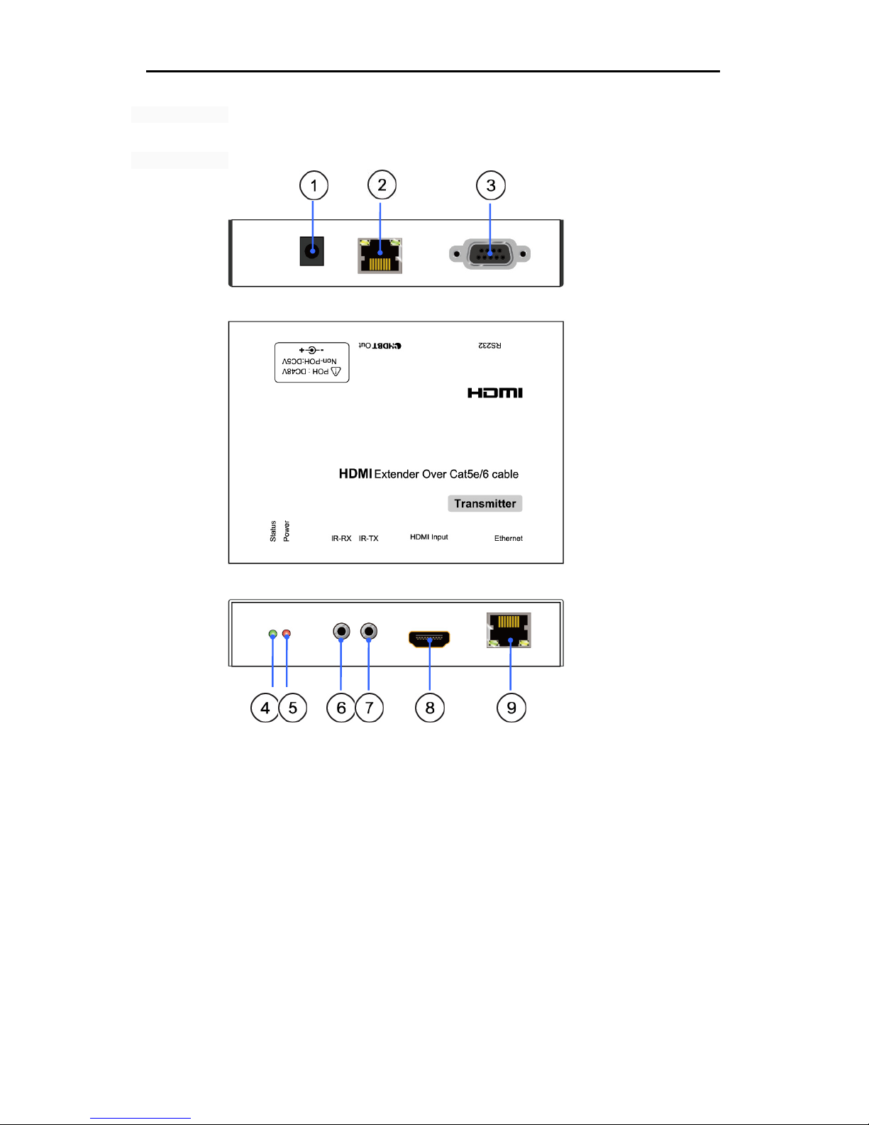
Panel Description
Transmitter Panel
1)DC input port- The 5V DC is the power input for the transmitter
2)HDBaseT port-This is for the Cat5e cable connection between the two units.
A.yellow LED-The LINK LED indicates that an HDBaseT link connection has been established between the two boards over the
Cat5e cable.
B.green LED-
a. When the LED is on, it indicates that video content with HDCP protection is being transferred.
b. When the LED is blinking, it indicates that video content without HDCP protection is being transferred.
c. When the LED is off, it indicates that no video is being transferred.
3)RS232 – This connector has a dual purpose
A:In its default mode, it may be used for serial RS232 data transfer over the HDBaseT link
B:When connected to a user’s PC it serves as a debug interface(See Update instruction)
4)LED Indicators:status–when blinking indicates the device is active.
5)LED Indicators:Power–The PWR LED indicates that power is available to the unit.
6)IR-RX port - This jack can be used for connecting IR-RX cable.
7)IR-TX port - This jack can be used for connecting IR-TX cable.
8)HDMI Input port
9)Ethernet port–There is one standard Ethernet port.

Operation instruction
5
Update instruction:
①Open the case of transmitter, find these two jumper caps.
PDIF0
PMS
According to the silk prints nearby (“PMS” for firmware update, “PDIF0”for RS232 transmission), change the jumper
caps’ positions to set RS232 port’s function.
②The user should receive a Firmware burn package, containing all software needed for burning and updating the
Firmware on the EEPROM.
③Connect RS232 port use RS232 cable from RS232 port of unit to PC.
④Power the unit.
⑤Extract the zipped file from the burn package to a directory (e.g. C:\dir_name).
⑥Browse to the directory (e.g. C:\dir_name\) and double click the batch file Update Source. bat(for Transmitter) or
Update Sink. Bat (for receiver).
A short description of the link created between the PC and the board appears on the screen, followed by the burn
progress percentage report.
⑦A second stage of verifying the content of the EEPROM follows, also with a progress percentage report
Operation instruction
6
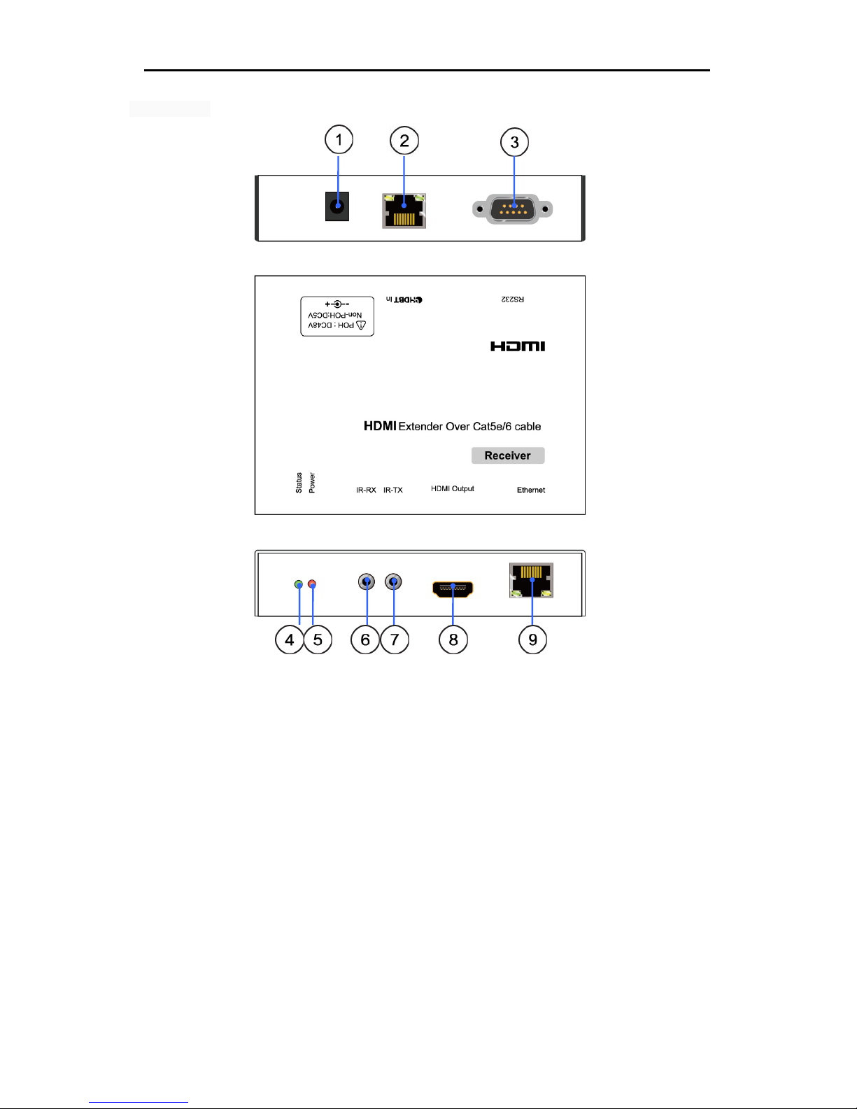
Receiver Panel
1) DC input port- The 5V DC is the power input for the receiver
2) HDBaseT port-This is the Cat5e cable connection between the two units.
A:yellow LED-The LINK LED indicates that an HDBaseT link connection has been established between the two boards over the
Cat5e cable.
B:green LED-
a.When the LED is on, it indicates that video content with HDCP protection is being transferred.
b.When the LED is blinking, it indicates that video content without HDCP protection is being transferred.
c.When the LED is off, it indicates that no video is being transferred.
3) RS232 – This connector has a dual purpose
A:In its default mode, it may be used for serial RS232 data transfer over the HDBaseT link
B:When connected to a user’s PC it serves as a debug interface(See Update instruction)
4) LED Indicators:status–when blinking indicates the device is active.
5) LED Indicators:Power–The PWR LED indicates that power is available to the unit.
6) IR-RX port - This jack can be used for connecting IR-RX cable.
7) IR-TX port - This jack can be used for connecting IR-TX cable.
8) HDMI Output port
9) Ethernet port–There is one standard Ethernet port.
Operation instruction
7
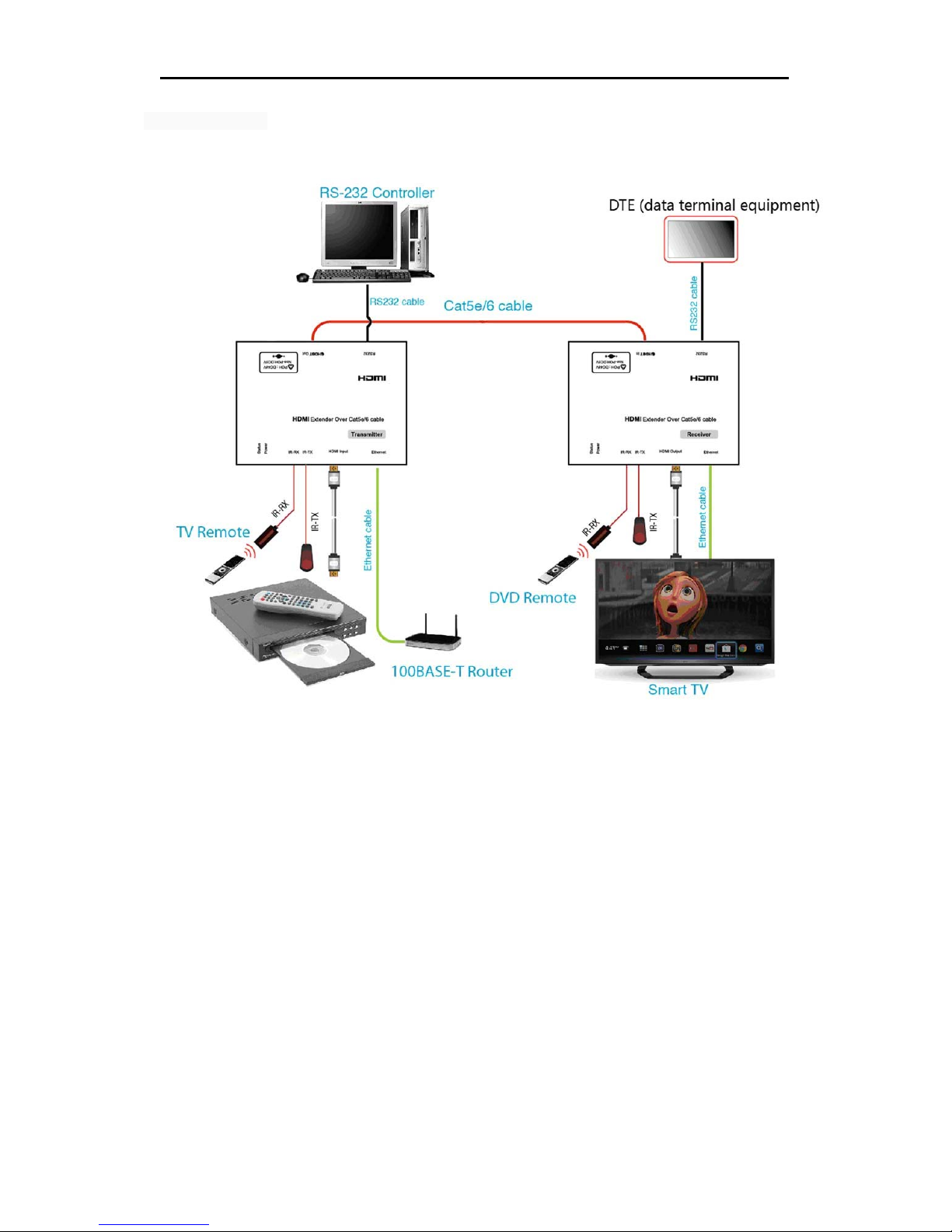
Connection Diagram
Application
CONNECTING AND OPERATING
1) Connect the HDMI signal source (Such as DVD, STB etc) to HDMI Transmitter.
2) Connect cat5e/6 cables to both HDBaseT port of the transmitter and HDBaseT port of the Receiver.
3) Connect the HDMI output (Such as HD-LCD, HD-DLP) into the Receiver.
4) Connect the IR-TX cable into transmitter IR-TX port on the back panel and affix the emitter onto the source IR windows ,Connect the
IR-TX cable into receiver IR-TX port on the back panel and affix the emitter onto the sink IR windows.
5) Connect the IR RX receiving cables into IR-RX port of receiver, and affix the IR RX near or on the video Display frame or stand within
direct line of sight with the hand held remote,connect the IR-RX cable into the transmitter to control the sink.
6) Turn on all devices.
Attention: Insert/Extract cables gently.

Operation instruction
8
Safety information
safeguards
To reduce the risk of electric shock, do not expose this product to rain or moisture
PRODUCT SERVICE
1) Damage requiring service: The unit should be serviced by qualified service personnel if:
(a)The DC power supply cord or AC adaptor has been damaged;
(b)Objects or liquids have gotten into the unit;
(c)The unit has been exposed to rain;
(d)The unit does not operate normally or exhibits a marked change in performance;
(e)The unit has been dropped or the cabinet damaged.
2) Servicing Personnel: Do not attempt to service the unit beyond that described in these operating instructions. Refer all other servicing
to authorized servicing personnel.
3) Replacement parts: When parts need replacing ensure the servicer uses parts specified by the manufacturer or parts that have the
same characteristics as the original parts. Unauthorized substitutes may result in fire, electric shock, or other hazards.
4) Safety check: After repairs or service, ask the servicer to perform safety checks to confirm that the unit is in proper working condition.
Table of contents
Other HDBaseT Extender manuals


