HDOEI SP50 User manual

Maintenance Manual
Issued .… 18th,Feb,2006
Revised…..
Auto-Laser Level
SP50/SP50A
Changzhou Huada Kejie Opto-Electro Instrument Co.,Ltd

SP50/SP50AAutomatic Laser Level
Content list
1. Preface
1-1 Notes
1-2 Scope of Repairing
1-3 Spare parts and Figures
1-4 Procedure for Disassembly and Re-assembled
1-5 Flow chart for Trouble shooting
2. Accuracy Checking
2-1 Horizontal Accuracy Checking
2-2 Vertical Accuracy Checking
3. Accuracy calibrations
3-1 Horizontal Accuracy calibrations
3-2 Vertical Accuracy calibrations
Preface
Never attempt to look at the laser beam directly. Laser beam is harmful for eye.
It is safer when laser beam rotating. Because passing through only for a short time.
1-1 Notes
SP50 is an automatic electronic laser level with laser diode of 635nm wavelength. Before repairing,
pay great attention to important precaution as follows.
Description of the laser unit
Be sure good body grounding to prevent laser diode from short life time caused by static electricity
in the unit.
1. Before disconnecting the plugs of the laser unit from the jack, turn power switch off.
2. Don’t touch the PCB of laser unit by hand.
3. Use special battery as power supply. Avoid as possible to useAC-DC stabilizer.
4. Don’t operate to switch ON-OFF repeatedly during short time. The PCB of the unit replacing and
the compensator repairing should be performed by manufacturer. It is also recommended to entrust
the manufacturer to solve the difficulties, when replacing parts and repairing dampness parts.
Introduction of maintenance instruction manual
This maintenance instruments manual is used only for checking and adjusting without special
instruments for SP50 laser level with visible laser rays of wavelength 635nm.
1-2 Scope of Maintenance
The instrument is provided after adjusted. Don’t disassemble the instruments or attempt to perform
any internal servicing, except instructions noted and permitted in this manual.
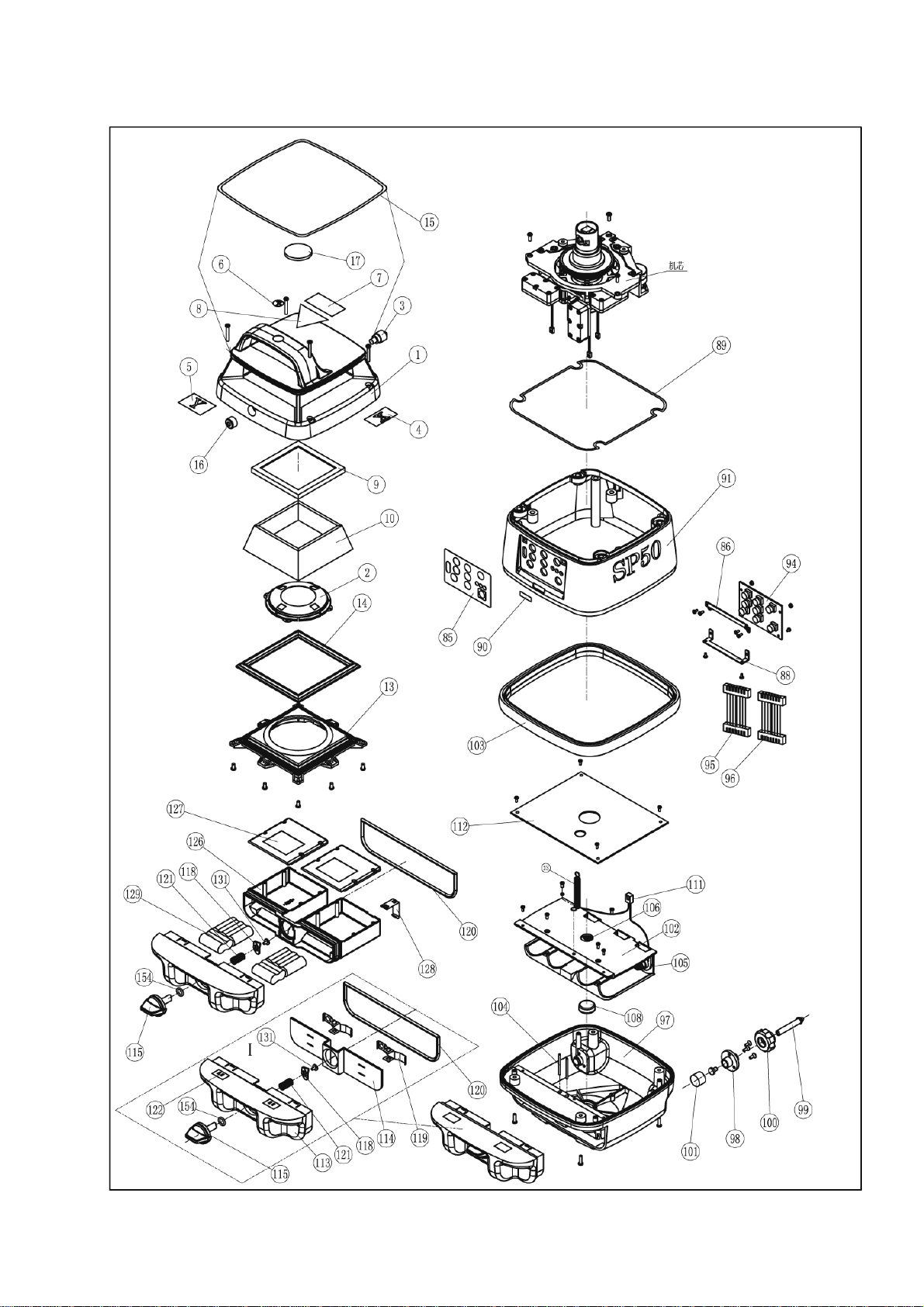
1-3 Spare parts and Figures

B001

Parts
No. Description Qty. Parts
No. Description Qty.
1 Plastic upper cover 1 40 Washer 1
2 Bow plastic cover 1 41 Stick 1
3 Support point 1 42 Axis 1
4 X Stick label 1 43 Whorl 1
5 Y Stick label 1 44 O washer 1
6 Symbol label 1 48 Encode PCB 1
7 Caution label A 1 53 Washer 1
8 Caution label B 1 85 Operating panel 1
9 Waterproof rubber A 1 86 Frame support 1
10 Beam window 1 88 Frame support 1
13 Window supporter 1 89 Rubber seal 1
14 Waterproof rubber B 1 90 S/N stick 1
15 Decorative rubber 1 91 Plastic housing 1
16 Bubble vial 1 94 Keypad 1
17 Upward window 1 95 Cable A 1
18 Drawtube 1 96 Cable B 1
20 Sensor support 1 97 Base body 1
21 Lens 1 102 Plastic cover 1
22 Quoit screw 1 103 Waterproof rubber 1
23 Spring 1 104 Lock pin 2
24 Main frame 1 105 Battery spring(single) 1
25 Motor frame 1 106 Battery spring(double) 1
26 Universal bearing 1 108 Metal cover 1
27 Plastic supporter 1 111 Battery cable 1
28 Limiting joint 1 112 Main control PCB 1
29 L supporter 1 130 Screws 6
30 Pin 2 132 Screws 4
31 Rotation head 1 135 Screws 4
32 Penta prism 1 137 Screws 1
33 Rotation axis 1 140 Screws 7
34 Plastic gear 1 142 Screws 3
35 Plastic encode 1 144 Screws 4
36 Whorl 1 156 Bearing 2
37 Adjusting whorl 1 A001 Rechargeable battery Box
(115,118,120,121,126,127,128,129,131,154) 1
38 Whorl 1 A002 Normal battery box 1
39 Cuneal lens 1 A003 Adjusting screw system 1
B001 Laser module 1 A004 Y motor system 1
B002 Sensor module 3 A005 X motor system 1
B003 Rotation part module 1 A006 Rotation motor module 1
B004 Penta prism module 1 B005 Cover assembly 1

The Fig. Of Cable and Plug
Power Scanning Rotation
Motor Y Step
Motor X
Step
LD Module
Y Range
Limiting
X Range
Limiting
Keypad A Keypad B
Sensor X
Sensor Y
Sensor Z
Step
Motor Y
LD
Module
Y
Range Step
Motor X
X
Range
Scanning
Rotation
Motor
Sensor X
Sensor Y
Sensor Z
1-4 Procedure for Assembling unit A001 module
①Remove rechargeable battery box
②Use cross screw driver to remove four L1 screws from fixed cover module B005. Take off B005.
③Use cross screw driver to remove four L2 screws which fix the housing and base. Take off 23 from
the mechanism unit.
④Take off the plug from mechanism module
⑤Remove three L3 screws. Then , remove two L4 screws. Turn and take off 48
⑥Remove the pentagonal prism module B004 from the mechanism module.
⑦Turn and take off 43 with the tweezers and remove 44. Then remove the rotating part B003.
⑧Turn and take off four L5 screws. Then, take off X/Y axis adjusting parts A004/A005.
⑨remove the screws which fix the rotating motor moduleA006. Take offA006.
⑩Remove four screws which fix 112 and take off main control PCB 112.
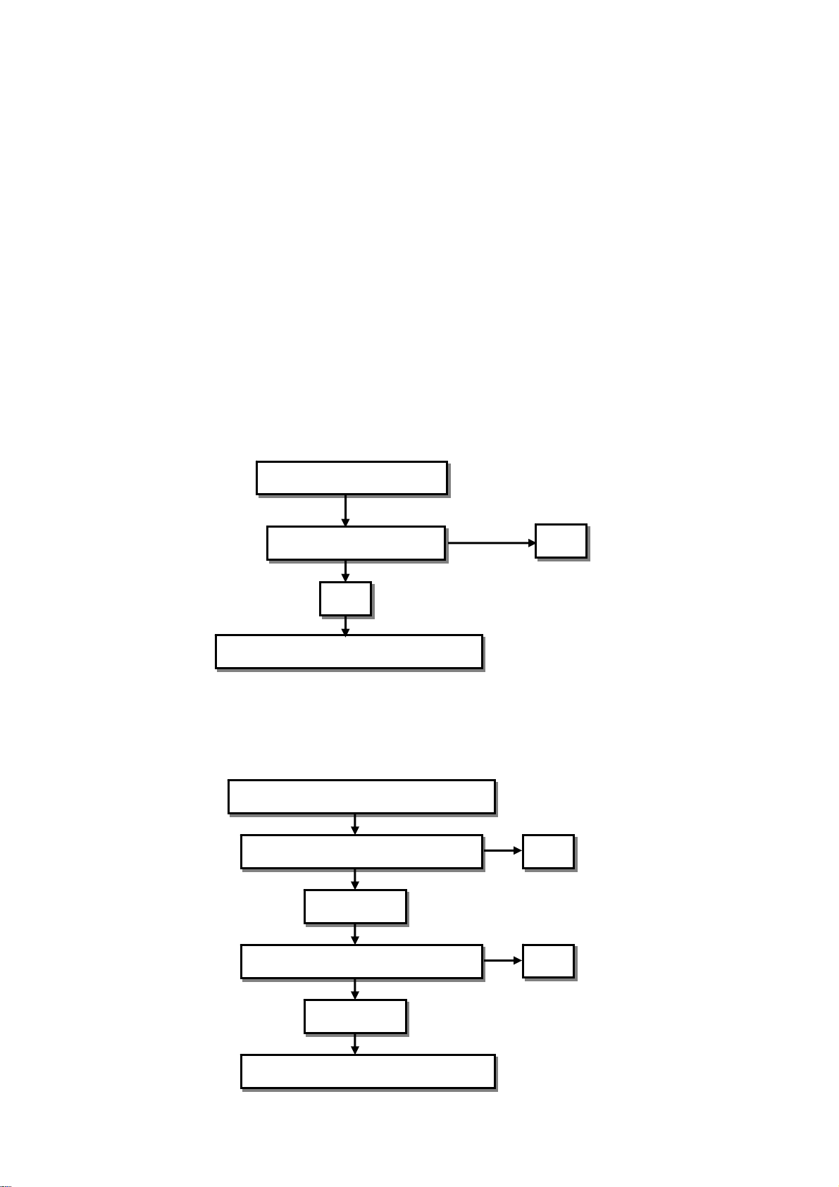
1-5 Flow chart for trouble diagnosis
1-5-1 Description: After adjusting, unit not to be leveling. After turning on the unit, the unit will not stop
making leveling and laser beam will blink and will not rotate.
1-5-2 After inclining, unit to be alarming
Description: When unit placing on flat surface and turning on, the unit will incline to one side and the
laser beam will blink. At same time the unit will be alarming.
Unit is not making leveling
Replace Main PCB 112
NG
Return to manufacturer for repairing
OK
Unit to be alarming when unit tilting
Replace A004/A005 module OK
OK
NG
Replace main PCB 112
NG
Return to the manufacturer for repair
2. Accuracy checking
SP50 assigned direction
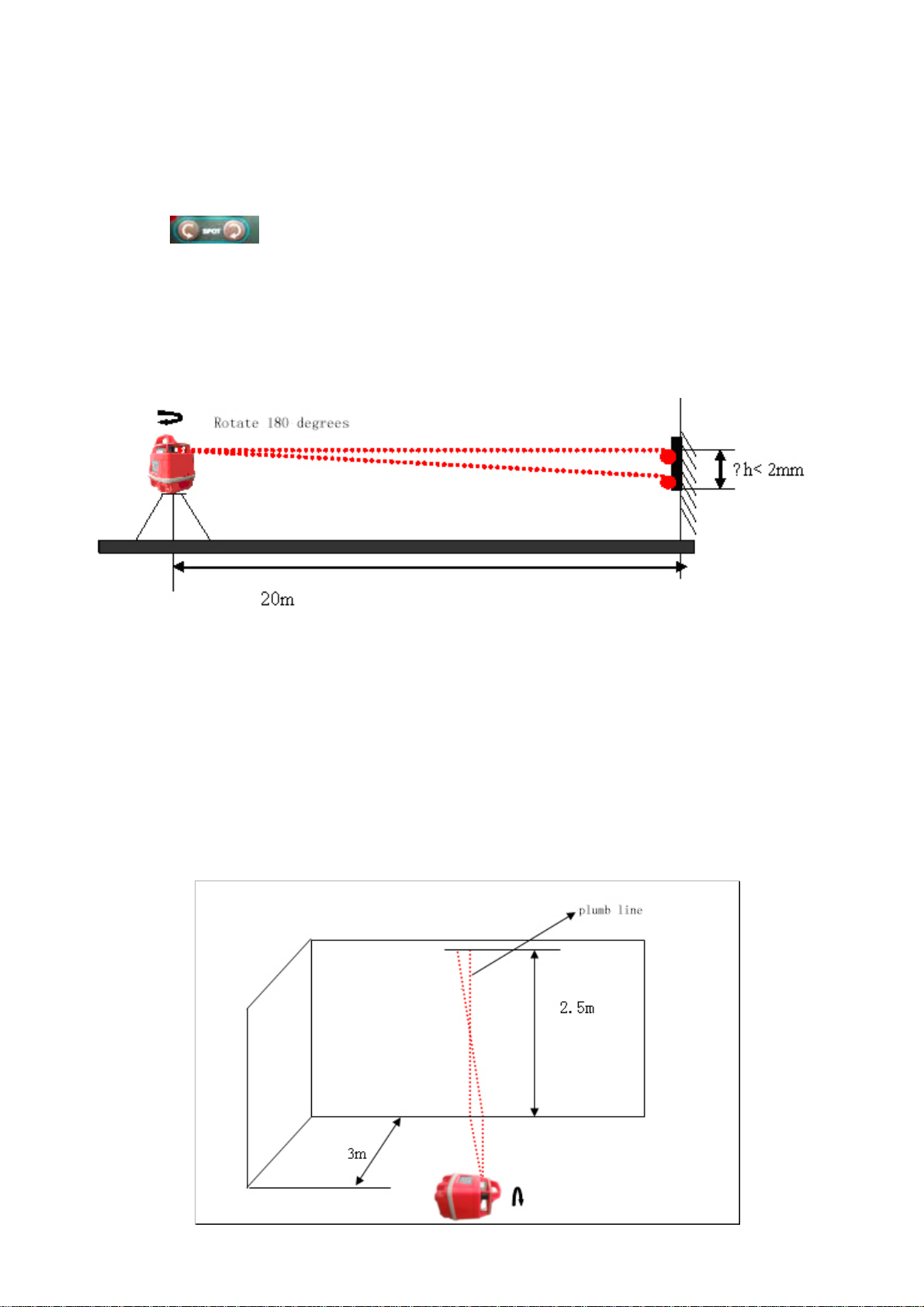
2-1 Horizontal accuracy checking
①place the unit on a flat surface 20m away from a wall. Position so that +x is facing the wall.
②Turn on the unit, after the unit rotating, press the key <<SPEED>> three times to stop the rotation
function. The transmitting laser beam will form a spot (laser point).
③Press〖〗to mark the position of the laser beam spot on the wall.
④rotate the laser 180 degrees so that –X faces the wall. After leveling, mark the location of the laser
beam spot closest to the first mark on the wall
⑤Normally, the two marks should be closer. In the 20m away, the difference(between the two marks)
should be less than 2mm.
⑥If the marks are not close enough(more than 2mm), the X direction needs to be calibrated. Check the
Y direction same way as X direction.
2-2 Vertieal accuracy checking
①Put the unit in vertical direction and place it on a flat plate 3m away from a plumb line. (Hanging a ball
in a wire with height 2.5m apart from the unit. If the unit needs calibration, it is better in a dark room.
②Adjusting the foot screws to ensure the round bubble in the middle of the vial
③Turn on the unit, After the unit rotating, press the key [speed], three times to stop the rotating and the
transmitting laser beam will make a spot on the wall.
④After switch to the spot- moving state, press [SPOT] to remove the spot. If the spot is overlapped in
the plumb line, it means the unit is within accuracy range. If the spot is inclined and not overlapped in
the plumb line, the Z direction needs to calibrate.

3. Accuracy calibrating (adjusting)
3-1 Horizontal accuracy calibrating
Keypaddisplay
①Put +X facing the wall. Turn on the unit. After leveling, press the key [CAL.] for five seconds until the
rotation to be stopped. Laser beam is transmitting and x light indicating is blinking. The unit is now
entering x calibrating
②Make the laser beam spot on the wall.
③Rotate the unit 180 degrees Mark the another spot on the wall. Make the height difference between
the two marks.
④Press the key [ ] to adjust the laser beam upward. Press the key [ ] to adjust the laser
beam downward Adjust the mark to the center of light spot of both +Y and –Y.
⑤Press the key [ CAL.] to change to Y .Calibration: Y indication light blinking. Calibrating Y is same
way as calibrating X
⑥After calibrating Y ,press the key [ CAL.] to save the data and to go back to normal operation from
calibrating. Then, press the key [I/O] to turn off the unit.
3-2 Vertical accuracy calibrating
①Put the unit in vertical. Turn on the unit. After leveling, press the key [CAL.] for five seconds. Then Z
indicating light is blinking and the rotation is stopped.. The unit is now entering Z axis calibrating.
②Press the two keys [ ] to make calibrating until the laser beam spot overlapping in the
plumb line from lower part to upper part.
③Press the key [CAL.] to confirm the calibrating to save the data, and to go back to normal operating
from calibrating. Then, press the key [I/O] to turn off the unit.
-Y
-X
+X
+Y
The Direction of
SP50
This manual suits for next models
1
Table of contents


