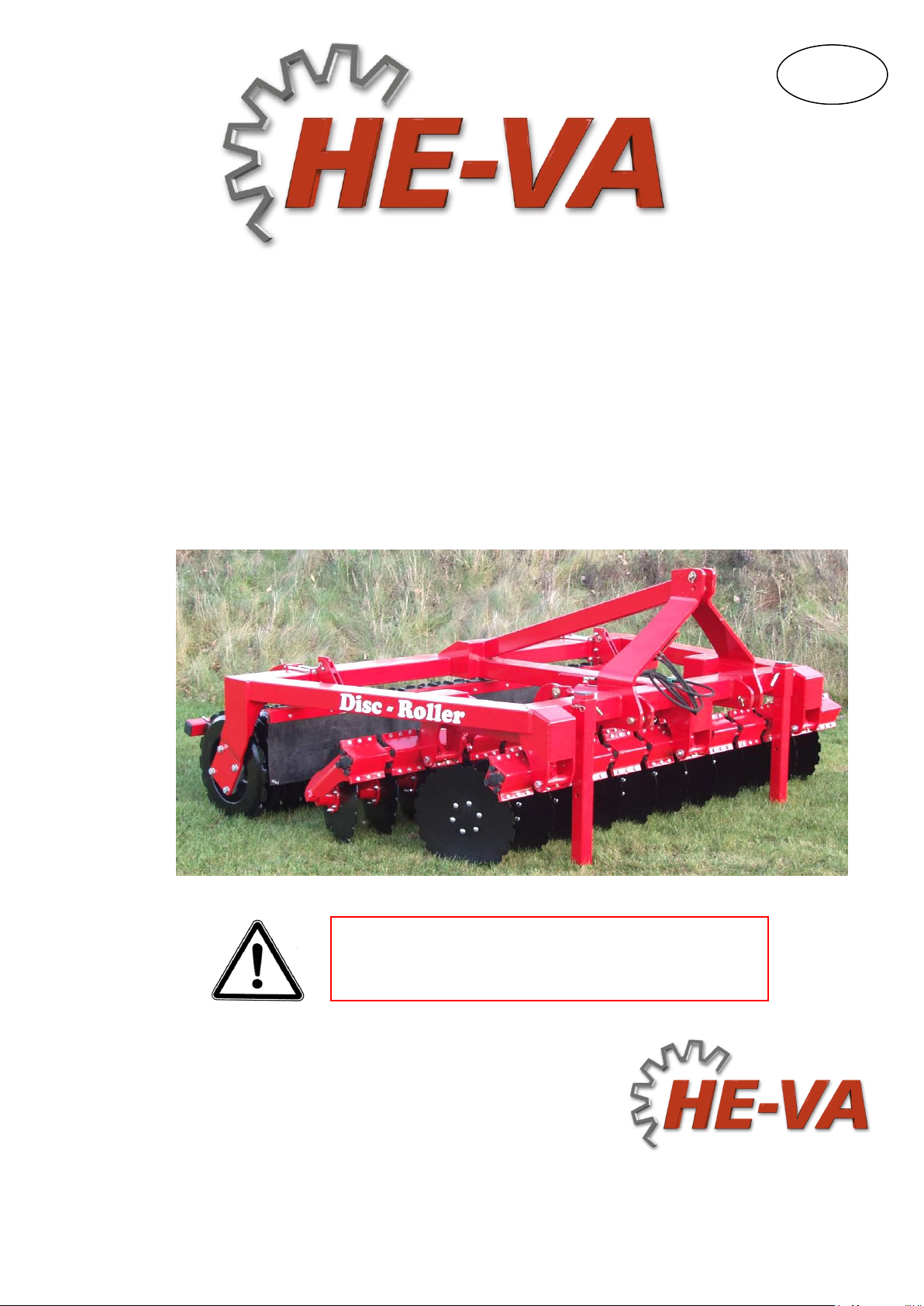
Disc-Roller 2,5 - 3,0 –3,5 - 4,0 m (1-section)
Contents
EC DECLARATION OF CONFORMITY............................................................................................................4
SAFETY INSTRUCTIONS FOR DISC-ROLLER...............................................................................................5
SAFETY AND INSTRUCTIONS ON HYDRAULICS ........................................................................................6
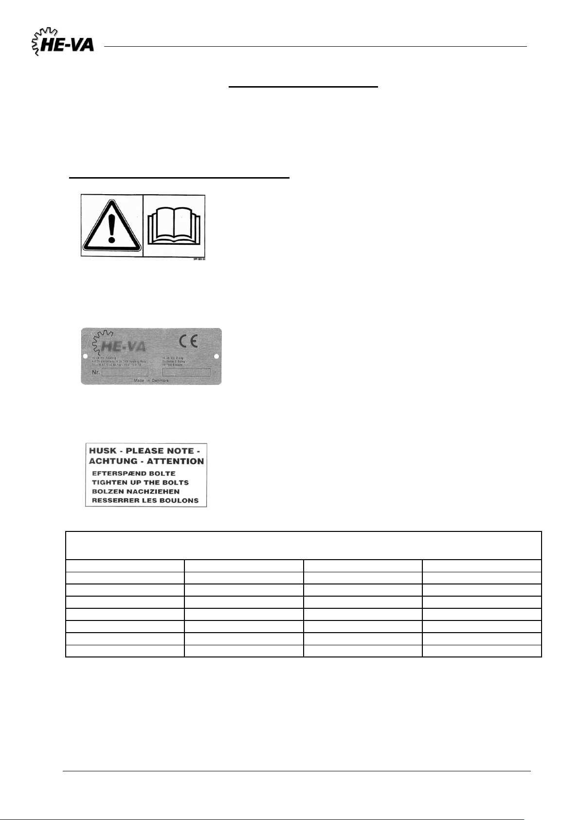
LABELS ON THE MACHINE...............................................................................................................................7
SAFETY –AND OTHER MARKINGS ON THE MACHINE...............................................................................................7
TECHNICAL SPECIFICATIONS / DATA ..........................................................................................................8
START-UP OF THE MACHINE...........................................................................................................................10
ATTACHMENT,MOUNTED MODEL.........................................................................................................................10
ATTACHMENT,TRAILED MODEL............................................................................................................................10
TRANSPORT...........................................................................................................................................................11
UNCOUPLING,MOUNTED MODEL ..........................................................................................................................11
UNCOUPLING,TRAILED MODEL.............................................................................................................................11
SETTINGS OG ADJUSTMENTS..........................................................................................................................12
DRAWBAR..............................................................................................................................................................12
DISC.......................................................................................................................................................................12
EDGE EQUIPMENT...................................................................................................................................................13
EDGE EQUIPMENT FROM MACHINE NO.341738......................................................................................................14
SCRAPER................................................................................................................................................................15
SCRAPER FROM 2009 -2013:..................................................................................................................................15
MATERIAL DAMPERGUARD ....................................................................................................................................16
TINE ERADICATOR SET (CAN ONLY BE MOUNTED ON TRAILED MODELS) ................................................................16
MAINTENANCE AND SERVICE.........................................................................................................................17
SPARE PARTS LIST ..............................................................................................................................................18
DRAWBAR (FOR TRAILED MODELS)........................................................................................................................18
WHEEL ASSEMBLY (FOR TRAILED MODELS) ...........................................................................................................22
DISC.......................................................................................................................................................................24
PACKING ROLLER...................................................................................................................................................26
SCRAPER................................................................................................................................................................28
EDGE EQUIPMENT...................................................................................................................................................30
EDGE EQUIPMENT FROM MACHINE NO.341738.......................................................................................................32
SPARE PARTS LIST - EXTRA EQUIPMENT....................................................................................................34
MATERIAL DAMPER GUARD ...................................................................................................................................34
SPRING-BOARD 2,5M +3,0M +3,5 M .....................................................................................................................36
SPRING-BOARD (LEFT)4,0M..................................................................................................................................37
EL.DEPTH STOP FOR DISC.......................................................................................................................................40
LIGHTS...................................................................................................................................................................42
HYDRAULIC BRAKES..............................................................................................................................................44
AIR BRAKES ...........................................................................................................................................................45
TINE ERADICATOR SET ...........................................................................................................................................47
SUPPORTING WHEEL (MODEL FOR SPRING-BOARD) ...............................................................................................49
SUPPORTING WHEEL (MODEL WITHOUT SPRING-BOARD).......................................................................................51
SPARE PARTS LIST - HYDRAULICS ................................................................................................................53
HYDRAULICS BETWEEN DRAWBAR AND WHEEL FRAME .........................................................................................53
HYDRAULICS FOR ADJUSTMENT OF DISC ................................................................................................................54
DIAGRAMS .............................................................................................................................................................57
EL.DEPTH STOP......................................................................................................................................................57
LIGHTS...................................................................................................................................................................58
HYDRAULICS F/DEPTH STOP ...................................................................................................................................59
HYDRAULICS F/EL.DEPTH STOP .............................................................................................................................59