HEADRUSH ZSIR150-20A Instruction manual

ZIPSTOP
ZIP LINE
BRAKE
Installation, Operation & Maintenance Manual
Models: ZS125-08 / ZSIR150-20A
NOTE TO INSTALLERS
Always Read Instructions Before Use
Leave this manual attached to the zipSTOP Brake unit. The Installation, Operation
and Maintenance manual contains information relating to the proper use of the
zipSTOP and includes all product registration and warranty information. This doc-
ument may only be removed by the end user prior to operation. Ensure that this
manual is readily available to operators at all times.
Head Rush Technologies zipSTOP Zip Line Brake Installation, Operation & Maintenance Manual
P/N 01170006604
Head Rush Technologies products are covered by a number of patents, including
U.S. Patents 8,490,751; 8,851,235; 9,016,435; 8,851,235 and D654,412 & corresponding patents/applica-
tions in the USA and in other countries worldwide.

3
www.headrushtech.com |+1-720-565-6885
TABLE OF CONTENTS
1. SAFETY INFORMATION 7
1.1 Symbols Used in this Manual 7
2. EMERGENCY ARREST DEVICE EAD CONFIRMATION 8
3. SAFETY & INFORMATION LABELS 9
3.1 Location of Safety Labels 9
4. WARRANTY INFORMATION 10
4.1 Warranty Conditions 10
4.2 Customer Responsibility 10
5. SPECIFICATIONS 11
5.1 Introduction 11
5.2 zipSTOP Brake Unit, ZS125-08 12
5.3 zipSTOP Brake Unit, ZSIR150-20A 13
5.4 zipSTOP Brake Trolley, ZS125-08 and ZSIR150-20A 14
6. OPERATING PRINCIPLES 15
6.1 General 15
7. ZIPSTOP BRAKE ASSEMBLY 16
7.1 General 16
7.2 Unpacking the zipSTOP 16
7.3 Long Term Storage 17
7.4 Supplied Parts 18
7.5 General and Additional Parts Required 18
7.6 Redirection Pulleys 19
7.7 Traveler Assembly 19
7.8 Minimum Hardware Requirements 20
7.9 Redirection Line 20
7.9.1 Redirection Line Specifications: ZS125-08/ZS150-20A 21
8. ZIPSTOP BRAKE ASSEMBLY CONFIGURATION 22
8.1 General 22
8.2 Setup Variables, ZS125-08/ZSIR150-20A 22
8.3 Rider Arrival Speed 23
8.4 Rider Weight 23
8.5 Redirection Line Ratio 23
8.5.1 1:1 Ratio 24
8.5.2 2:1 Ratio 25
8.6 POSSIBLE SYSTEM CONFIGURATIONS (INFORMATIVE ONLY) 26
8.6.1 3:1 Ratio 26
8.6.2 Other Configurations 27
8.7 Zip Line Slope 27
8.7.1 Positive Slope Line 28
8.8 Flat Line 28
8.9 Negative Slope Line 29
8.10 Calculating zipSTOP Braking Distances 29
8.10.1 Definition of Terms 30

4www.headrushtech.com |+1-720-565-6885
8.11 zipSTOP Braking Distance Charts 31
8.12 Configuration Notes 31
8.13 zipSTOP Configuration Worksheet 33
9. ZIPSTOP BRAKE ASSEMBLY INSTALLATION 34
9.1 General 34
9.2 Safety Precautions 34
9.3 Primary Anchor Point 35
9.4 Secondary Anchor Point 35
9.4.1 Position of the Secondary Anchor Point 36
9.5 Redirection and Support Lines 36
9.6 Fitting zipSTOP Brake Unit 37
9.7 Fitting the Brake Trolley 40
9.8 Fitting Type I Pulley 42
9.9 Fitting Type II Pulley 43
9.10 Fitting Redirection Line 43
9.11.1 1:1 Redirection Ratio 44
9.11.2 2:1 Redirection Ratio 46
10. OPERATION OF ZIPSTOP 49
10.1 Safety Precautions 49
10.2 zipSTOP Operation as a Primary Brake 50
10.3 zipSTOP Operation as an EAD 50
10.4 Landing Areas 50
10.5 Operation During Extreme Weather Conditions 51
10.6 Resetting the Brake 51
10.7 Operational Retraction Spring Cycle Limit 52
11. TROUBLESHOOTING 53
11.1 Before You Call 57
12. RECERTIFICATION AND MAINTENANCE 58
12.1 General 58
12.2 Annual Recertification 58
12.3 Maintenance Service Schedule 58
12.4 Daily Inspections 59
12.4.1 Safety Precautions 59
12.4.2 Webbing Wear 60
12.5 Braking Line Replacement Procedure 63
12.6 Brake Trolley Inspection and Maintenance 65
12.7 Brake Unit Casing Inspection 65
12.8 Webbing Line Inspection 66
13. BRAKING DISTANCE CHARTS 67
13.1 How to Read Braking Distance Charts 67
13.2 1:1 Ratio – Metric, ZSIR150-20A 68
13.3 1:1 Ratio – Imperial, ZSIR150-20A 68

5
www.headrushtech.com |+1-720-565-6885
13.4 1:1 Ratio – Metric ZS125-08 69
13.5 1:1 Ratio – Imperial ZS125-08 69
13.6 2:1 Ratio – Metric, ZS125-08 70
13.7 2:1 Ratio – Imperial, ZS125-08 70
13.8 3:1 Ratio – Metric 71
13.9 3:1 Ratio – Imperial 71
14. APPENDIX A: EAD WARRANTY/REGISTRATION FORM 72
14.1 Warranty Registration Form 72
15. APPENDIX B: ACCESSORIES AND REPLACEABLE PARTS 73
15.1 Accessories and Replacement Parts 73
15.2 Brake Trolley Catch Accessory 73
15.2.1 Specifications 74
15.2.2 Composition 74
15.2.3 Mounting/Installation 74
15.2.4 Operation 77
15.2.5 zipSTOP Brake Unit Side Cover Replacement 80
15.2.6 zipSTOP Brake Unit Nozzle Replacement 80
15.2.7 Removing Nozzle Assembly 80
15.2.8 To Refit the Nozzle Assembly: 81
15.2.9 Brake Trolley Bump Stop Replacement 82
15.2.10 Service Life 82
15.3 zipSTOP Pivot Mount 82
15.3.1 Composition 83
15.3.2 Mounting 83
15.3.3 Installation 84
15.3.4 Performance 86
15.3.5 Service Life 86
15.3.6 Inspection Procedures 87
16. APPENDIX C: EXAMPLE INSPECTION LOGS 88
17. MANUFACTURER’S DETAILS 90

IMPORTANT SAFETY NOTICE
Zip Lining is a Dangerous Activity
Read Before Installation & Operation
Failure by the installer or operator to heed any and all instructions, warnings and cautions for the correct
installation, operation, care and maintenance of the zipSTOP may result in serious injury or death.
The zipSTOP Brake assembly, including zipSTOP Brake Unit Model ZB125-08B and ZSIR150-20A, zipSTOP
Brake Trolley Model ZT125-17 and all associated equipment are designed and specified for use in the recre-
ational zip line industry as components of a well designed zip line brake system. Use of the zipSTOP compo-
nents for any purposes other than that intended by the manufacturer is not permitted.
The zipSTOP is designed to be utilized as a Primary Brake or Emergency Arrest Device (EAD). When using the
zipSTOP as a primary brake, the installer MUST utilize an independent EAD to protect against operator error
and third party equipment failure. Design and installation of the zip line, including the complete braking sys-
tem, is the responsibility of the installer or operator.
Owners and Operators of zipSTOP devices are responsible for the safety and supervision of any person using
the zipSTOP and are required to assure that proper installation and operation procedures are followed at all
times. Proper installation requires careful design and planning using zipSTOP and non-zipSTOP components.
Owners and Operators are encouraged to seek the advice of their zip line installer or a proper engineering
professional regarding the instructions in this Manual.
These instructions must be made readily available to the operator at all times. Prior to installation and use, all
owners, installers and operators must have read and shown to have understood all instructions, labels, markings,
and safety information pertaining to the installation, operation, care, and maintenance of the zipSTOP brake, its
component parts, and all associated hardware. Failure to do so may result in equipment damage, serious injury
and death.

7
www.headrushtech.com |+1-720-565-6885
1. SAFETY INFORMATION
1.1 Symbols Used in this Manual
The following safety symbols are used throughout this manual to highlight potential danger to operators and
equipment. One or more precautions may be associated with practices and procedures described within this
manual. Failure to adhere to any precautions highlighted can result in equipment damage, serious injury and/
or death.
Ensure that you read and understand all safety related procedures related to the working environment and the
task you are undertaking.
DANGER
Indicates a hazardous situation exists that, if not avoided, will result in serious injury or death.
WARNING
Indicates a potentially hazardous situation that, if not avoided, could result in serious injury or
death.
CAUTION
Indicates a potentially hazardous situation that, if not avoided, may result in injury or equip-
ment damage.
NOTE
Indicates an action that must be taken to ensure personal safety and prevent damage to
property or equipment.
CARE FOR THE ENVIRONMENT
Take care to minimize impact on the environment when carrying out this procedure.

8www.headrushtech.com |+1-720-565-6885
2. EMERGENCY ARREST DEVICE (EAD) CONFIRMATION
Zip lines using the zipSTOP Brake are required to use both primary and emergency arrest devices functioning
together to arrest the motion of passengers. The EAD must engage with no input from the passenger upon
failure of the primary arrest device.
This form must be initialed by the performing EAD installation technician, signed by a separate party and at-
tached when mailing in the Warranty Registration Form; failure to do so may void your warranty .
I have read this manual prior to zipSTOP installation and use. INITIAL:
I am aware that an approved EAD is required prior to system use. INITIAL:
I certify that an approved EAD has been correctly installed prior to system use. INITIAL:
I have inspected the installation of the EAD and certify its functionality.
SIGNED: DATE:

9
www.headrushtech.com |+1-720-565-6885
3. SAFETY & INFORMATION LABELS
Safety and Information Labels located on the zipSTOP components are not to be removed. Ensure labels are
in place and remain legible at all times.
3.1 Location of Safety Labels
Location of Labels – Brake Unit
Location of Labels – Brake Trolley

10 www.headrushtech.com |+1-720-565-6885
4. WARRANTY INFORMATION
4.1 Warranty Conditions
Manufacturers sole warranty. The zipSTOP Brake assembly will be sold free from defects in materials and
workmanship, excluding field replaceable wear parts, for a period of one (1) year from date of purchase. This
warranty only applies to the original purchaser, and is contingent upon the owner/operator using and main-
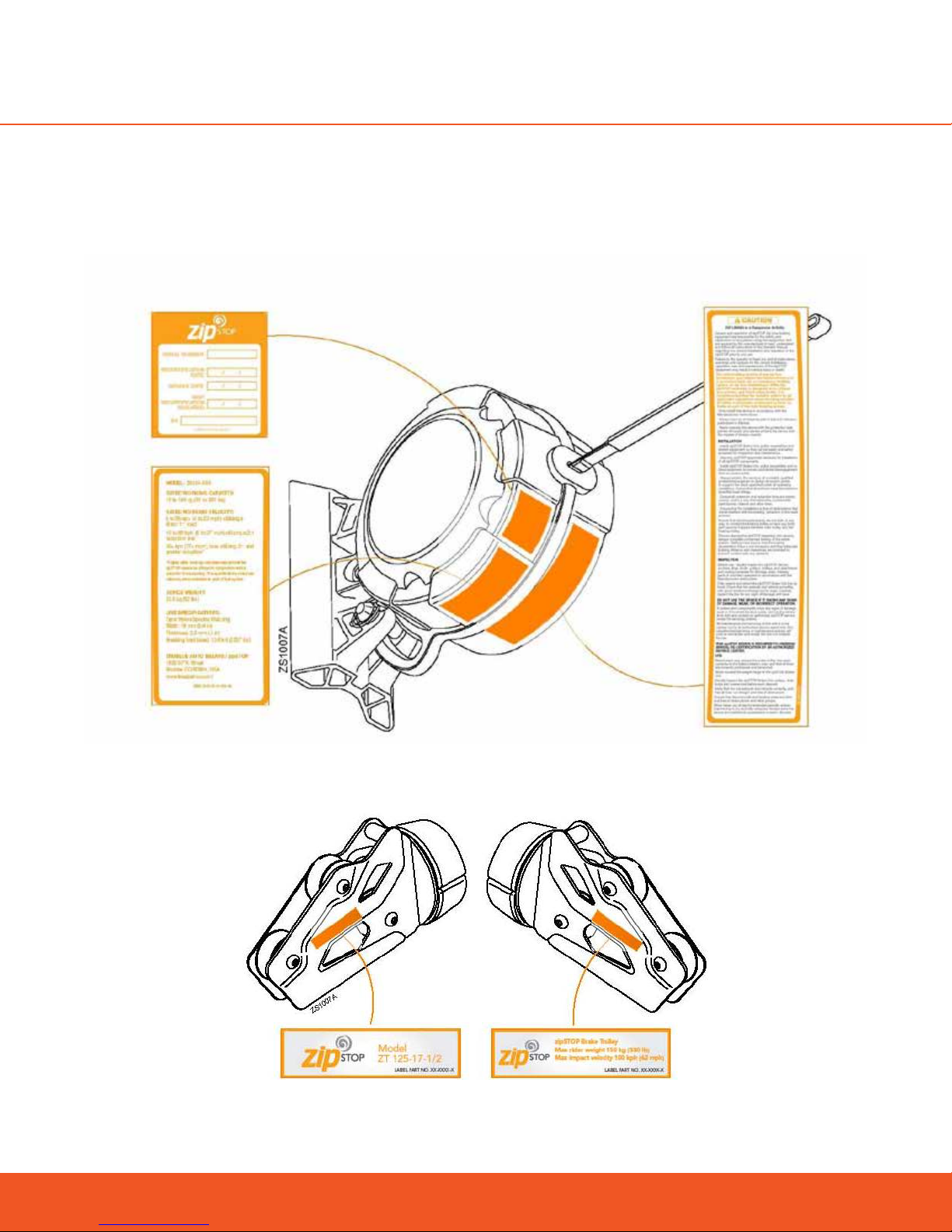
taining the device in accordance with the zipSTOP instructions, including the requirement to maintain annual
recertification as described in the Installation, Operation and Maintenance Manual.
THIS WARRANTY IS EXPRESSLY IN LIEU OF OTHER WARRANTIES, EXPRESS OR IMPLIED, AND ANY IMPLIED
WARRANTY OF MERCHANTABILITY OR FITNESS FOR A PARTICULAR PURPOSE IS HEREBY EXPRESSLY EX-
CLUDED.
The sole remedy for breach of said warranty or for any claim in negligence or strict liability in tort is the repair
or replacement of any defective parts at the discretion of the manufacturer. Such parts claimed to be defec-
tive shall be returned to the Head Rush Technologies Service Center, transportation prepaid, for inspection by
zipSTOP to determine to its satisfaction that said part(s) are defective.
This warranty is null and void if other than genuine parts are used, or if any modifications are carried out to the
zipSTOP Brake assembly or zipSTOP components without the expressed written permission of the manufac-
turer. No person, Agent or Distributor is authorized to give any warranty, other than the one herein expressed,
on behalf of the zipSTOP Company or to assume for it any liability pertaining to such products. The company
makes no warranties in respect to trade accessories or component parts which are not manufactured by the
company, same being subject only to such warranties, if any, as may be made by their respective manufacturers.
4.2 Customer Responsibility
The following items are considered to be the responsibility of the Customer and, therefore, are non-reimburs-
able under the terms of the warranty:
Correct installation of an EAD.
Sucient unmanned testing of the entire system.
Normal maintenance/routine services.
Normal replacement of service items.
Replacements required because of abuse, misuse or incorrect operation of equipment by the installer or
operator.
Field replaceable wear parts such as the nozzle, braking line, quick links, redirection line and pulleys,
brake trolley sacrificial bump stops, and sheaves supplied as zipSTOP branded parts.
Normal wear and tear due to use and exposure.
Strict adherence to the Installation, Operation and Maintenance Manual supplied, manufacturer’s instructions
and advice given by zipSTOP service technicians is also a condition of warranty (see Appendix A: EAD Warran-
ty/Registration Form).

11
www.headrushtech.com |+1-720-565-6885
5. SPECIFICATIONS
5.1 Introduction
The zipSTOP Brake assembly is a controlled braking force device designed specifically for use in the zip line
industry as a Primary or EAD at the end of zip line runs. The zipSTOP caters to a range of rider weights and
approach speeds, and oers a smooth, consistent braking force for all riders. The brake is designed to be
mounted to a primary and/or secondary anchor point to slow the decent of riders on a zip line. The primary
anchor point is exactly what it sounds like; it is the main attachment point for the brake. The secondary an-
chor point is the support point for the redirection lines and pulleys.
The zipSTOP Brake Unit is installed at the end of the zip line, usually on or adjacent to the terminal end. A
Secondary Anchor Point is normally required upstream of the landing area to provide support for the Redi-
rection Line pulleys. Alternately a full-length secondary cable of sucient capacity can be installed to provide
support for the Redirection Line and associated pulleys.
The design of the zipSTOP allows for simple installation, and incorporates both an advanced self-regulating
brake unit and an automatic line reset. The patented braking mechanism delivers smooth deceleration and
is designed to minimize variations in the deceleration rate and stopping distance of both children and adults.
There are no friction parts in the brake mechanism, ensuring reliability remains high while maintenance and
operating costs are kept to a minimum.
Installation, inspection, operation and maintenance must be carried out in accordance with the instructions in
this manual to protect the longevity of the zipSTOP components.
Pictures in this manual are for reference purposes in terms of geometry and proposed redirection setup
configuration only. Mandated EAD may or may not be shown.

12 www.headrushtech.com |+1-720-565-6885
5.2 zipSTOP Brake Unit, ZS125-08
MODEL ZS 125-08B
CLASSIFICATION Zip Line Braking Device
DIMENSIONS 380 x 320 x 216 mm (15 x 12.6 x 8.5 in)
NET WEIGHT 23.5 kg (52 lbs)
OPERATING TEMPERATURE -10°C (14°F) to 40°C (104°F)
STORAGE TEMPERATURE -20°C (-4°F) to 60°C (140°F)
MATERIALS CASING Aluminium alloy
INTERNAL PARTS Zinc plated and stainless steel
NOZZLE Modified Acetal plastic with stainless insert
LINE 20 mm Nylon Spectra Braking Line
MAXIMUM LINE EXTENSION 12.5 m (41 ft)
RIDER WEIGHT RANGE 15 to 150 kg (33 - 330 lbs)
MAXIMUM SPEEDS 1:1 REDIRECTION RATIO 36 km/h (22 mph)
2:1 REDIRECTION RATIO 60 km/h (37 mph)
3:1 REDIRECTION RATIO* Contact Head Rush Tech
CUSTOM RATIO* Contact Head Rush Tech
*Higher speeds may be utilized with the custom Redirection Ratios, however braking distances will increase.
When planning a custom ratio, note that the automatic line reset may become compromised, requiring the
necessity for either manual reset or supplementary reset.
zipSTOP Mount
Top Mounting Pin
zipSTOP Brake Unit
Nozzle Assembly
Braking Line
Pulley
Side Cover
Fully Retracted - 400 mm (16”)

13
www.headrushtech.com |+1-720-565-6885
5.3 zipSTOP Brake Unit, ZSIR150-20A
MODEL ZSIR150-20A
CLASSIFICATION Zip Line Braking Device
DIMENSIONS 380 x 320 x 216 mm (15 x 12.6 x 8.5 in)
NET WEIGHT 23.5 kg (52 lbs)
OPERATING TEMPERATURE -10°C (14°F) to 40°C (104°F)
STORAGE TEMPERATURE -20°C (-4°F) to 60°C (140°F)
MATERIALS CASING Aluminium alloy
INTERNAL PARTS Zinc plated and stainless steel
NOZZLE Modified Acetal plastic with stainless insert
LINE 20 mm Nylon Spectra Braking Line
MAXIMUM LINE EXTENSION 20 m (65 ft)
RIDER WEIGHT RANGE 15 to 150 kg (33 - 330 lbs)
MAXIMUM SPEEDS 1:1 REDIRECTION RATIO 60 km/h (37 mph)
ZSIR15020A THIS PRODUCT CAN ONLY BE USED WITH 1:1 REDIRECTION SETUPS
The zipSTOP IR (ZSIR150-20A) is NOT compatible with external redirection setups in any way. Installing
a redirection setup with the zipSTOP IR can create a very dangerous set of braking conditions that could
result in abnormally abrupt late braking.
zipSTOP Mount
Top Mounting Pin
zipSTOP Brake Unit
Nozzle Assembly
Braking Line
Pulley
Side Cover
Fully Retracted - 400 mm (16”)

14 www.headrushtech.com |+1-720-565-6885
5.4 zipSTOP Brake Trolley, ZS125-08 and ZSIR150-20A
MODELS ZT 125-17-1/2 – For use with 12.7 mm (½”) zip lines
ZT 125-17-3/4 – For use with 19 mm (¾”) zip lines
ZT 125-17-35/8 – For use with 15.9 mm (5/8”) zip lines
CLASSIFICATION Zip Line Brake Trolley
DIMENSIONS 235 x 100 x 115 mm (9.3 x 3.9 x 4.5 in)
NET WEIGHT 1.3 kg (2.8 lbs)
MATERIALS CASING Aluminium alloy
WHEELS Steel
BUMP STOP Polyurethane
MAXIMUM SPEED 72 km/h (45 mph)
MINIMUM RIDER WEIGHT 15 kg (33 lbs)
MAXIMUM RIDER WEIGHT 150 kg (330 lbs)
Bump Stops
Lower Sheaves
Upper Sheave
Redirection Line
Mounting Point

15
www.headrushtech.com |+1-720-565-6885
6. OPERATING PRINCIPLES
6.1 General
The zipSTOP Brake assembly is a controlled braking force device designed specifically for use as a Primary or
EAD at the end of zip line runs. The zipSTOP caters to a range of rider weights and approach speeds and oers
a smooth, consistent braking force for all riders. zipSTOP Brake performance relies on operators using the
correct equipment and operating the system in accordance with the instructions contained within this manual.
The zipSTOP Brake assembly consists of a zipSTOP Brake Unit, zipSTOP Brake Trolley, redirection pulleys and
associated Redirection Lines.
Pictures in this manual are for reference purposes in terms of geometry and proposed redirection setup
configuration only. Mandated EAD may or may not be shown.
Typical zipSTOP Installation
The zipSTOP Brake Unit is located at the zip line terminal end, normally adjacent to the landing area. It is
connected via a redirection pulley and Redirection Line setup to the zipSTOP Brake Trolley.
The Brake Trolley is located on the zip line and when idle (zipSTOP Braking Line fully retracted) will be
positioned at the start of the rider Arrest Zone (Reset Position). The approaching rider trolley contacts
the Brake Trolley, moving it down the zip line. As the Brake Trolley moves into the Arrest Zone it extends
the Braking Line out of the zipSTOP Brake Unit via the Redirection Line. As the Braking Line extends out
of the zipSTOP Brake Unit, the eddy current brake in the unit is activated, controlling the rate of deceler-
ation and slowing the rider in a smooth manner.
Once the load is removed from the Brake Trolley, the return mechanism in the zipSTOP Brake Unit
retracts the Braking Line, automatically returning the Brake Trolley to the start of the Arrest Zone (Reset
Position) on the zip line, ready for the next rider.
When higher Redirection Ratios are employed retraction force is reduced and a manual reset of the Brake
Trolley may be necessary.
Ensure brake is reset before rider starts down zip line, every time.
Primary
Mount
Redirection
Line Support
Redirection Line
Cable Clamps &
Quick Links
zipSTOP Brake Unit
zipSTOP Brake Line Brake Trolley
Redirection Pulley
Overhead Line
Brake Line Extension
Arrest Zone
Zip Line
Rest Position

16 www.headrushtech.com |+1-720-565-6885
7. zipSTOP BRAKE ASSEMBLY
7.1 General
The zipSTOP Brake assembly will be supplied as a kit of parts. Additional components are required to com-
plete the braking system. Refer to Section ”Appendix B: List of Accessories and Replaceable Parts” for part
number information.
Pictures in this manual are for reference purposes in terms of geometry and proposed redirection setup
configuration only. Mandated EAD may or may not be shown.
7.2 Unpacking the zipSTOP
SAVE PACKAGING FOR REUSE
Keep all zipSTOP packaging for reuse when returning the zipSTOP Brake Unit for annual recertification.
Damages caused by shipping in improper packaging are not covered under warranty and will result in addi-
tional repair charges to the owner.
Brake Assembly Kit
1. Upon receipt of the zipSTOP Brake Assembly Kit, inspect all parts and operation (pull out line) for signs
of shipping damage or contamination. If any components show signs of damage or mishandling, con-
tact your zipSTOP distributor.
2. Check that all information and safety labels axed to the zipSTOP are present and legible. Refer to
Section “Location of Safety Labels”.

17
www.headrushtech.com |+1-720-565-6885
Do not use the zipSTOP after date shown here
3. Check the Certification Label on the zipSTOP Brake Unit for the ‘Next Recertification Required’ date. If
the date shown has passed or the label is missing or illegible then the zipSTOP Brake Unit must not be
put into service.
4. Register online at www.thezipshop.com/registration or fill out the Product Registration Card included
with the zipSTOP Brake Assembly Kit, and return it to your zipSTOP distributor.
5. The EAD Confirmation form and the Warranty Registration form (see Sections “Emergency Arrest De-
vice (EAD) Confirmation” and “Warranty Registration Form” respectively) are required to be detached,
filled out, and mailed to:
Head Rush Technologies
1835 38th Street , STE C
Boulder, CO 80301
PRODUCT REGISTRATION MUST BE COMPLETED
The Product Registration must be completed, either by registering online or by filling out and returning the
Product Registration Card. This is critical for receiving product notifications and up-to-date information for
the proper use of the zipSTOP Brake assembly.
6. Read this entire Installation, Operation and Maintenance Manual supplied with the zipSTOP, and famil-
iarize yourself with all aspects of installation, operation, care and maintenance.
7.3 Long Term Storage
If the zipSTOP Brake Unit is to be placed into storage or left unused for longer than two weeks, ensure the unit
is clean and dry and protected from the environment. Ensure the Braking Line is fully retracted into the unit.
Always store in a clean and dry environment, preferably in the original packaging
DO NOT STORE BRAKE UNIT IN A WET CONDITION
After exposure to water or damp conditions, thoroughly clean and dry the zipSTOP prior to storage. Ensure
that the zipSTOP Brake Unit is not left with a wet Braking Line retracted inside the casing as this may result
in corrosion of the unit and deterioration of the Braking Line. In a clean and dry environment, remove the
side covers and fully extend the wet Braking Line and allow to completely dry prior to storing the Brake Unit.
Ensure that debris does not enter the unit and reattach the side covers prior to storing or using the unit.

18 www.headrushtech.com |+1-720-565-6885
When returning the zipSTOP Brake assembly to operation after an extended period of inactivity, always carry out a
full inspection and operational check of all components in the assembly. Refer to Section “Operation of zip-
STOP” for Inspection procedures.
7.4 Supplied Parts
The following parts will be included in each Brake Assembly Kit:
1 x zipSTOP Brake Unit
1 x zipSTOP Mounting Bracket, Rattle Stop, Mounting and Lynch Pins
1 x zipSTOP Brake Trolley
zipSTOP Installation, Operation and Maintenance Manual
Brake Unit Brake Unit Mounting Bracket
ZIPSTOP
ZIP LINE
BRAKE
Installation, Operation & Maintenance Manual
Models: ZS125-08 / ZSIR150-20A
NOTE TO INSTALLERS
Always Read Instructions Before Use
Leave this manual attached to the zipSTOP Brake unit. The Installation, Operation
and Maintenance manual contains information relating to the proper use of the
zipSTOP and includes all product registration and warranty information. This doc-
ument may only be removed by the end user prior to operation. Ensure that this
manual is readily available to operators at all times.
Head Rush Technologies zipSTOP Zip Line Brake Installation, Operation & Maintenance Manual
P/N 01170006604
Head Rush Technologies products are covered by a number of patents, including
U.S. Patents 8,490,751; 8,851,235; 9,016,435; 8,851,235 and D654,412 & corresponding patents/applica-
tions in the USA and in other countries worldwide.
Brake Trolley Installation, Operation, & Maintenance Manual
7.5 General and Additional Parts Required
Additional lines and equipment will be required to successfully install a zipSTOP Brake assembly within individ-
ual zip line installations. All hardware, fasteners and accessories used in the installation of zipSTOP must meet
or exceed the required loads and specifications, and must be made of materials compatible with all-season
outdoor use.
Head Rush Technologies developed specific redirection pulleys and the Gorilla rope to maximize the perfor-
mance of a zipSTOP Zip Line Brake. The redirection pulleys oered by Head Rush Technologies are light-

19
www.headrushtech.com |+1-720-565-6885
weight, corrosion resistant, and engineered to be virtually resistant to snagging. Head Rush Technologies also
oers the Gorilla Rope, a 6mm rope specifically designed for used as a redirection line.
7.6 Redirection Pulleys
The following parts are not supplied as part of the zipSTOP kit and may be purchased separately from your
zipSTOP distributor.
The Type I Pulley is fitted to the Secondary Anchor Point, and provides both support and a means of redirec-
tion for the Redirection Line. The Type I Pulley is required for both 1:1 and 2:1 Redirection Ratio setups.
A Type II Pulley is fitted between the zipSTOP Brake Unit and the Type I Pulley as required to provide support
and redirection for the Redirection Line and connections to the Braking Line. The Type II Pulley is only re-
quired on the 2:1 Redirection Ratio set-ups.
Example of Type I Redirection Pulley Example of Type II Redirection Pulley
7.7 Traveler Assembly
The Traveler Assembly is a recommended support for a 2:1 ratio configuration. It is used to support the weight
of the Redirection Line and associated hardware in order to ensure that the Redirection Line does not contact
any surface other than the pulley sheaves. A sling of proper length should be used to ensure that the Braking
Line feeds straight out of the device, without twist, and centered within the Nozzle. A swivel is recommended
to ensure that the Braking Line remains free of twists.
Pulleys
Triangular Quick-
link
Swivel
Sling
Oval Quicklink
zipSTOP Brake Line

20 www.headrushtech.com |+1-720-565-6885
7.8 Minimum Hardware Requirements
All required hardware is to be purchased separately. The following are minimum requirements for all hardware
used for zipSTOP installation:
DESCRIPTION SIZE QTY NOTES
ZIPSTOP BRAKE UNIT MOUNTING
BOLTS, WASHERS & LOCKNUTS
M12 or 1/2” 3
Grade 4.6 (M12)
ASTM A307 Grade A or B (1/2”)
Length to suit installation
Suitable for all-season outdoor use
TYPE I PULLEY MOUNTING
HARDWARE To suit To suit Suitable for all-season outdoor use
CARABINERS, SNAPS, RINGS,
THIMBLES, CLEVISES To suit Minimum load rating 15 kN
Suitable for all-season outdoor use
7.9 Redirection Line
The Redirection Line is required to connect the zipSTOP Brake Unit to the Brake Trolley and will transfer the
braking force from the Brake Unit. The Redirection Line passes through the redirection pulleys and must meet
minimum specification. The following list provides several Redirection line options.
Head Rush Technologies developed the Gorilla Rope specifically for use as a redirection line with the zipSTOP
Zip Line Brake It features a high strength-to-weight ratio, is designed to be highly resistant to abrasion, UV
resistant, and water repellent. The 6mm Gorilla Rope maximizes performance because it is lighter, smaller in
diameter, minimizes resistance, and maximizes reliable reset.
Spectra - Spectra/Dyneema is one of the recommended materials because it has sucient strength while
minimizing size and diameter. Spectra/Dyneema is known for high strength and superior abrasion, water, and
UV resistance. The spectra line should be jacketed with an abrasion-resistant, temperature-tolerant material
to avoid possible degradation of the line due to friction. Gorilla Rope, a Head Rush Technologies product, is
designed specifically to provide high strength, a long life span, and minimal stretch for applications where a
small diameter rope is necessary. It is made for maximum durability and high performance in any application.
It is perfect for use as a reduction line with the zipSTOP Zip Line Brake but can also be used for many other
industrial or recreational applications where these qualities are critical.
Technora® - Technora, while the strongest of the synthetic fibers, is particularly sensitive to UV wear. Only
Technora core lines with UV protective jackets should be used. Technora lines are also slightly stier which
can increase retraction drag when used as a Redirection Line. The drag is usually oset by the fact that a
smaller diameter Technora line can be employed compared to another material.
Typical Technora Termination
Nylon and Other materials - Nylon or other materials can be used provided they meet the minimum require-
ments for strength, UV, and wear resistance. However, these lines may necessitate much larger diameter ropes
to attain the necessary strength which can have an adverse eect on Redirection Line performance.

21
www.headrushtech.com |+1-720-565-6885
7.9.1 REDIRECTION LINE SPECIFICATIONS: ZS12508/ZSIR15020A
MAXIMUM DIAMETER 10.0 mm/0.394 in (6mm/0.236 in recommended)
MINIMUM STRENGTH 13 kN, Stretch <3% at 13 kN
STRETCH <4% at 15 kN
WEAR RESISTANCE High abrasion resistance and UV resistance
WATER RESISTANCE Dry, non-absorptive
TYPE Kernmantle or single braid construction
TYPICAL Redirection LINE EXAMPLE
ZS125-08
TYPICAL Redirection LINE EXAMPLE
ZS150-20A
ALWAYS USE THE SPECIFIED REDIRECTION LINE
Failure to utilize a Redirection Line of specified strength and quality can compromise zipSTOP brake opera-
tion, resulting in equipment damage, serious injury or death.
REDIRECTION LINE WILL BE SUBJECT TO WEAR AND ABRASION
Any Redirection Line selected for use will wear and must be replaced from time to time. Lines must be care-
fully inspected prior to use each day, and failure to do so may result in serious injury or death.
When selecting a Redirection line, the following considerations apply:
The line must meet the specifications described above.
A lighter, smaller diameter line is preferred, to minimize resistance and weight, and maximize reliable
reset.
A waterproof line is required. Water absorption can add significant weight, allowing the line to sag
which increases the likelihood of incomplete reset for Brake Unit and Brake Trolley.
This manual suits for next models
1
Table of contents
Popular Accessories manuals by other brands

La Crosse Technology
La Crosse Technology 925-1418 Quick setup guide

Altinex
Altinex TNP461 user guide

IFM Electronic
IFM Electronic efector 250 installation instructions

Siko
Siko MS500 quick start guide

Philips
Philips DLA67020D brochure

Scame electrical solutions
Scame electrical solutions OPTIMA-EX 24V Series Installation, use and maintenance

PCB Piezotronics
PCB Piezotronics IMI SENSORS EX641B02 Installation and operating manual

Tascam
Tascam US-2000 owner's manual

Grizzly
Grizzly G5938 instructions

Manitowoc
Manitowoc MFD-50 Replacement manual

IFM Electronic
IFM Electronic efector 800 VSE100 operating instructions

nvent
nvent Raychem MONI-PT100-4/20MA manual