Siko MS500 User manual

MS500+MB500 Datum 26.08.2008 Art.Nr. 80296 Änd. Stand 318/08 1
MS500 Typ B
MS500 Typ L
MS500 Typ F
DEUTSCH
1. Gewährleistungshinweise
Lesen Sie vor der Montage und der Inbetriebnahme
dieses Dokument sorgfältig durch. Beachten Sie zu
Ihrer eigenen Sicherheit und der Betriebssicherheit
alle Warnungen und Hinweise.
Ihr Produkt hat unser Werk in geprüftem und be-
triebsbereitem Zustand verlassen. Für den Betrieb
gelten die angegeben Spezifikationen und die
Angaben auf dem Typenschild als Bedingung.
Garantieansprüche gelten nur für Produkte der
Firma SIKO GmbH. Bei dem Einsatz in Verbindung
mit Fremdprodukten besteht für das Gesamtsystem
kein Garantieanspruch.
Reparaturen dürfen nur im Werk vorgenommen
werden. Für weitere Fragen steht Ihnen die Firma
SIKO GmbH gerne zur Verfügung.
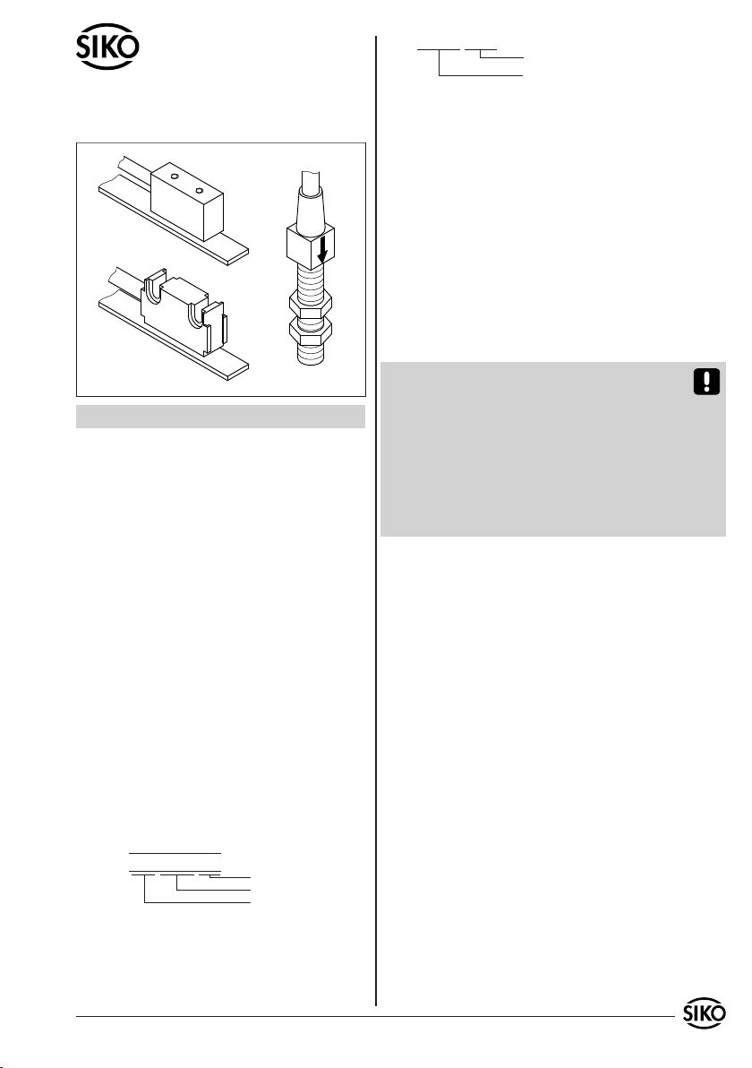
2. Identifikation
Magnetband: Das Magnetband ist durch eine fort-
laufende Bedruckung identifizierbar.
Beispiel Magnetbandbedruckung:
•
•
•
•
z.B. MS500-0023
Varianten-Nr.
Geräte-Typ
3. Mechanische Montage
Die Montage darf nur gemäß der angegebenen IP-
Schutzart vorgenommen werden. Das System muss
ggfs. zusätzlich gegen schädliche Umwelteinflüs-
se, wie z.B. Spritzwasser, Lösungsmittel, Staub,
Schläge, Vibrationen, starke Temperaturschwan-
kungen geschützt werden.
3.1 Montage Magnetband
Die Montage muss plan zur Montagefläche bzw. der
zu messenden Strecke erfolgen. Welligkeiten ver-
schlechtern immer die Messgenauigkeit.
Überall wo aufgrund unzureichender Befestigungsmöglichkeiten
keine geeignete Montage des Magnetbandes möglich ist, kann das
Magnetband Typ MB in eine als Zubehör lieferbare Profilschiene
(z.B. Typ PS oder PS1) montiert werden. Dadurch entsteht eine
kompakte Magnetbandeinheit.
Aus technischen Gründen muss bei der Länge,
gegenüber der Messstrecke, ein Zumaß von min.
47mm berücksichtigt werden.
Achtung! Um optimale Verklebungen zu errei-
chen müssen alle antiadhäsiven Fremdsubstanzen
(Öl, Fett, Staub usw.) durch möglichst rückstands-
los verdunstende Reinigungsmittel entfernt wer-
den. Als Reinigungsmittel eignen sich u.a. Ketone
(Aceton) oder Alkohole, die u.a. von den Firmen
Loctite und 3M als Schnellreiniger angeboten wer-
den. Die Klebeflächen müssen trocken sein und es
ist mit höchstmöglichem Anpressdruck zu verkle-
ben. Die Verklebungstemperatur ist optimal zwi-
schen 20°C und 30°C in trockenen Räumen.
Tip! Bei Verklebung langer Bänder sollte die
Schutzfolie des Klebebandes über eine kurze Teil-
strecke abgezogen werden, um das Band zu fixie-
ren. Daraufhin erfolgt das Ausrichten des Bandes.
Nun kann über die restliche Länge die Schutzfolie,
unter gleichzeitigem Andruck des Bandes, seitlich
herausgezogen werden. (als Hilfsmittel kann eine
Tapetenandrückwalze verwendet werden)
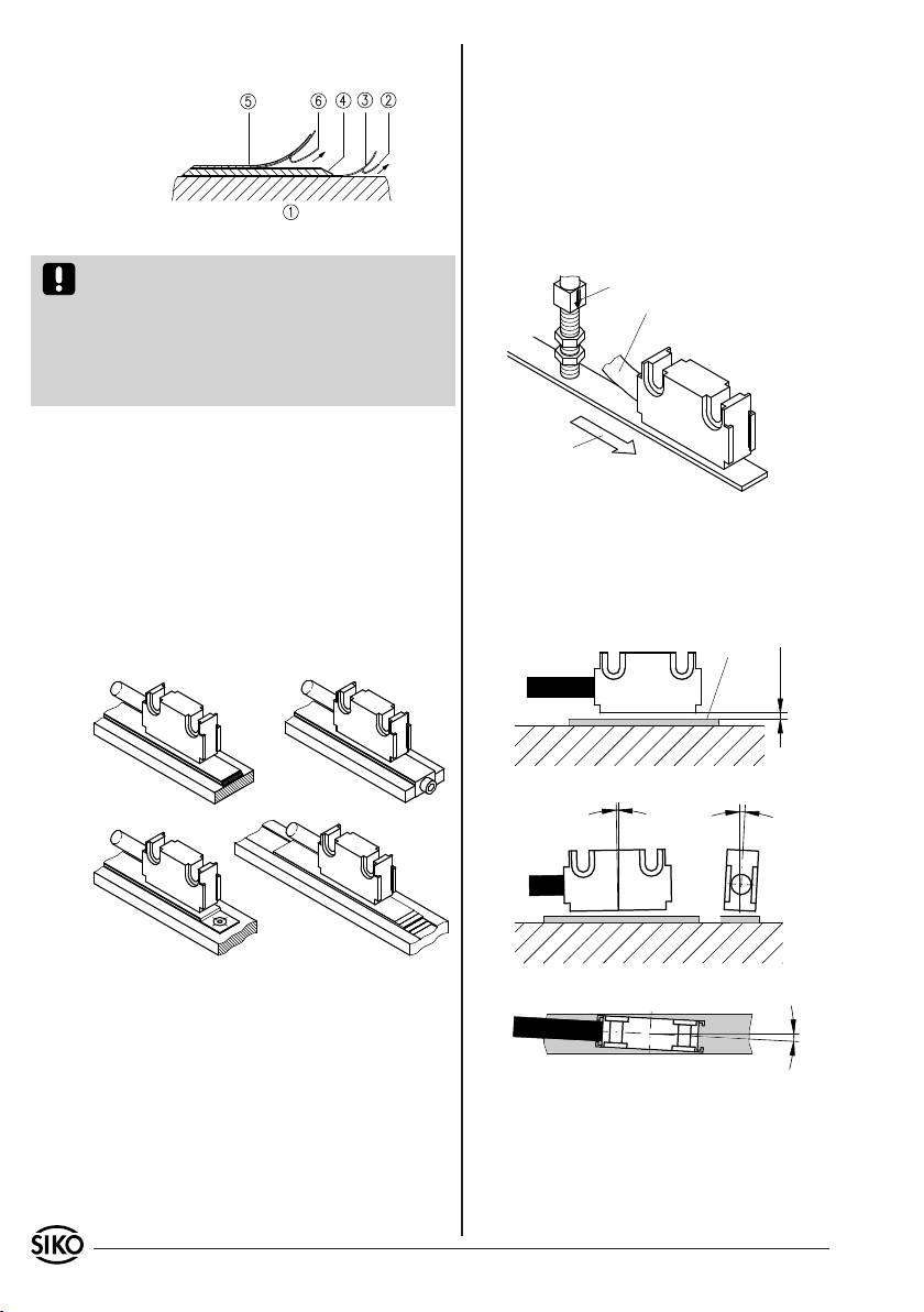
Montageschritte (Abb. 1)
Befestigungsfläche (1) sorgfältig reinigen.
Am Magnetband die Schutzfolie (2) des Klebe-
bandes (3) entfernen.
Magnetband (4) aufkleben.
Magnetbandoberfläche sorgfältig reinigen.
Am Abdeckband (5) die Schutzfolie (6) des Kle-
bebandes entfernen.
Abdeckband aufkleben (an beiden Enden leicht
überlappen lassen).
•
•
•
•
•
•
Benutzerinformation
MS500 + MB500
Magnetsensor und Magnetband
Polbreite: 5mm
Bandgenauigkeit: 0.1mm
Seriennummer
0
1
0
NNNN 0500
Magnetsensor: Das Typenschild zeigt den Ge-
rätetyp mit Variantennummer. Die Lieferpapiere
ordnen jeder Variantennummer eine detaillierte
Bestellbezeichnung zu.
2 MS500+MB500 Datum 26.08.2008 Art.Nr. 80296 Änd. Stand 318/08
Abb. 1: Montage Magnetband
Abb. 2 Abb. 3
Abb. 4 Abb. 5
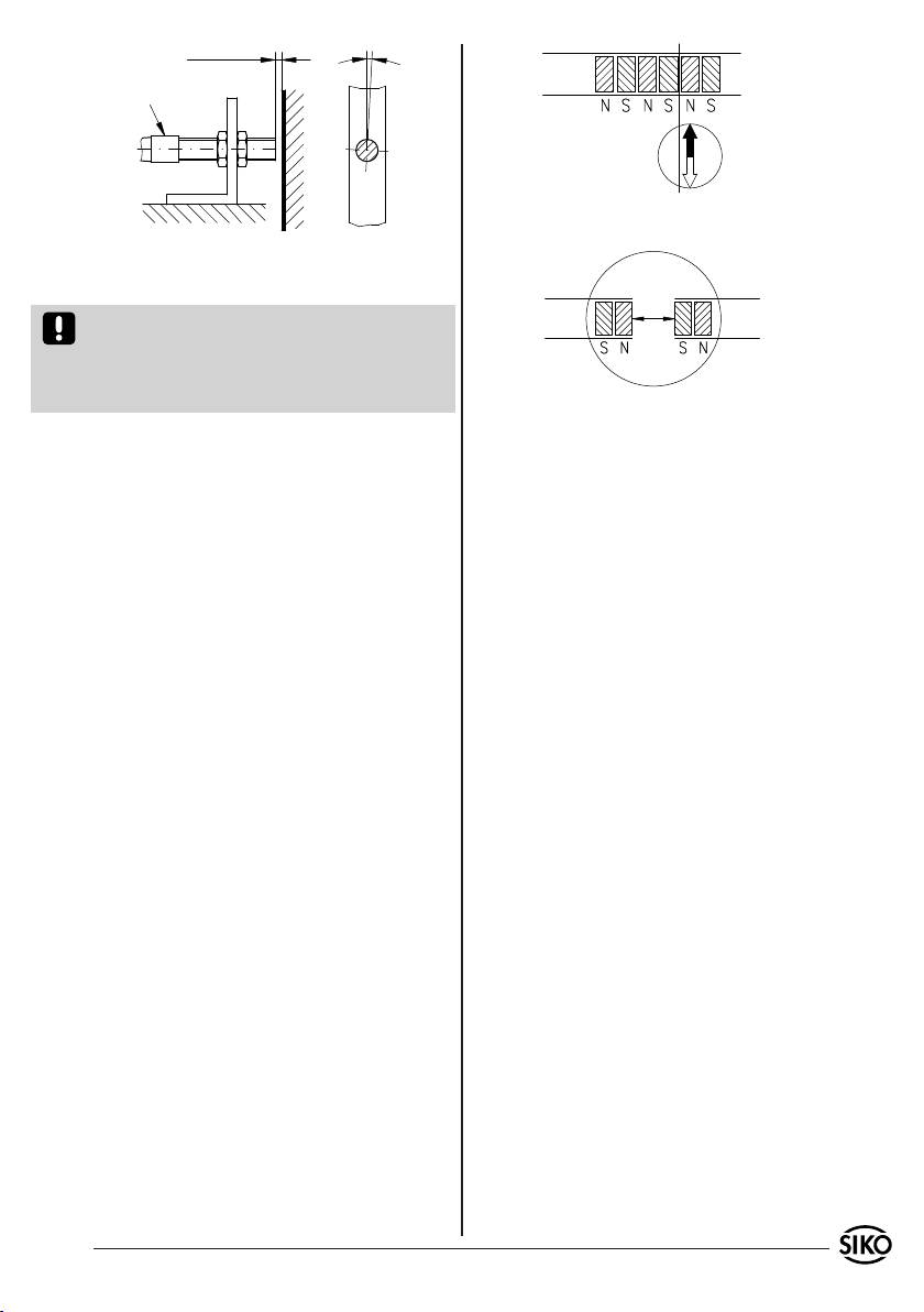
Abb. 7: Ausrichtung des Sensors Typ B oder L
aktive Seite
Abstand Sensor/Magnetband 0,1mm ... 2,0mm
<1° <3°
maximale Fluchtungsfehler
<3°
Abb. 6: Definition der Zählrichtung
Sensor F
Signal
B vor A
Pfeil
Sensor B oder L
Signal A vor B
Verfahrrichtung
Sensor
Kabelabgangsrichtung
Die überlappenden Enden des Abdeckbandes gegen
Ablösen sichern.
• Kabel sind so zu verlegen, dass keine Beschä-
digungsgefahr durch Zug oder andere Maschi-
nenteile besteht. Falls nötig Schleppkette oder
Schutzschlauch verwenden und Zugentlastung
vorsehen.
Auf richtige Ausrichtung bezüglich der Zähl-
richtung achten (Abb. 6). Dies ist unerheblich
falls sich die Zählrichtung in der elektronischen
Auswertung umkehren läßt. (wie z.B. bei den
Magnetbandanzeigen von SIKO)
•
•
Achtung! Die Beeinflussung durch magnetische
Felder ist zu vermeiden. Insbesondere dürfen keine
Magnetfelder (z.B. Haftmagnete oder andere Dau-
ermagnete) in direkten Kontakt mit dem Magnet-
band geraten. In stromlosem Zustand werden Be-
wegungen oder Verstellungen des Magnetsensors
von der Folgeelektronik nicht erkannt und erfasst.
Montagebeispiele
Die einfache Montageart, durch angeschrägtes
Schutzband (Abb. 2), ist nur in sehr geschützter
Umgebung zu empfehlen. Bei ungeschützer Um-
gebung besteht Abschälgefahr. In solchen Fällen
sind Montagearten, wie in Abb. 3 und 4 gezeigt,
geeigneter.
Den optimalen Schutz bietet die Montage in ei-
ner Nut (Abb. 5), die so tief sein sollte, dass das
Magnetband vollständig darin eingebettet werden
kann.
3.2 Montage Magnetsensor
Der Magnetsensor Typ B kann durch Verwendung
von 2 Schrauben M2,5 über Sacklochgewinde be-
festigt werden.
Die Magnetsensoren Typ L können durch Verwen-
dung von 2 Schrauben M3 über die ø3,1mm Durch-
gangslöcher befestigt werden.
Der Magnetsensor Typ F kann z.B. an einen Monta-
gewinkel mit entsprechender Befestigungsbohrung
durch Anziehen der zwei Muttern M8x0,5 befestigt
werden (Abb. 7).
Abstandmaße zwischen Sensor und Magnetband
sowie Winkeltoleranzen beachten, diese müssen
über die gesamte Messstrecke eingehalten werden!
(Abb. 7 und 8) Als Montagehilfe kann die beilie-
gende Abstandslehre verwendet werden.
•
MS500+MB500 Datum 26.08.2008 Art.Nr. 80296 Änd. Stand 318/08 3
Abb. 8: Ausrichtung des Sensors Typ F
0.1mm ... 2.0mm <3°
Pfeil
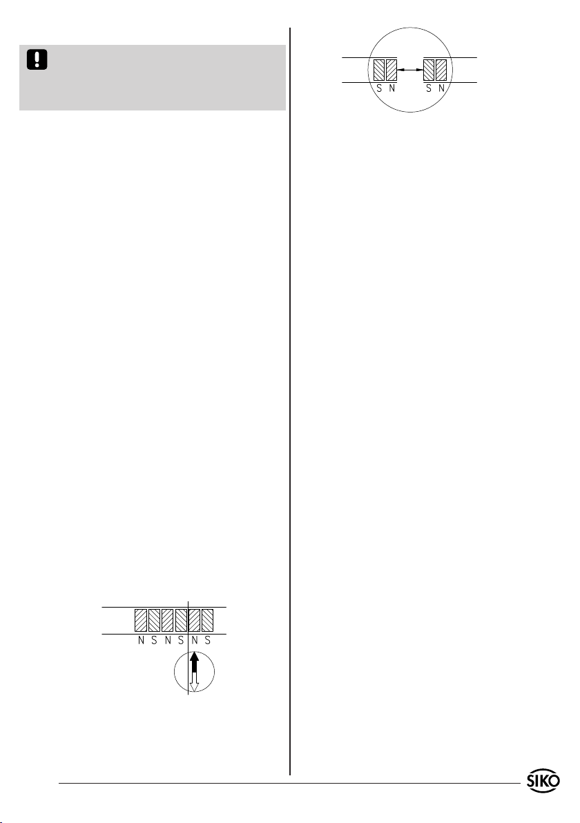
Abb. 9: Ermittlung der Polarität. Trennung des
Magnetbandes.
Abb. 10: Ermittlung der Polarität. Ansetzen des
Magnetbandes
4. Elektrischer Anschluss
Achtung! Diese Magnetbandsensoren sind vorbe-
reitet zum Anschluss an SIKO-Magnetbandanzei-
gen oder SIKO-Auswerteelektronik. Der Sensoran-
schluss darf nicht verändert werden (z.B. durch
Kabelverlängerungen).
Vor dem Einschalten sind alle Leitungsanschlüsse
und Steckverbindungen zu überprüfen.
Hinweise zur Störsicherheit
Alle Anschlüsse sind gegen äußere Störeinflüsse
geschützt. Der Einsatzort ist aber so zu wählen,
dass induktive oder kapazitive Störungen nicht
auf den Sensor oder dessen Anschlussleitung
einwirken können! Durch geeignete Kabelführung
und Verdrahtung können Störeinflüsse (z.B.von
Schaltnetzteilen, Motoren, getakteten Reglern
oder Schützen) vermindert werden.
Erforderliche Maßnahmen:
Das System muss in möglichst großem Abstand von
Leitungen eingebaut werden, die mit Störungen
belastet sind; ggfs. sind zusätzliche Maßnahmen
wie Schirmbleche oder metallisierte Gehäuse
vorzusehen. Leitungsführungen parallel zu Ener-
gieleitungen vermeiden.
Schützspulen müssen mit Funkenlöschgliedern
beschaltet sein.
5. Verlängern von Magnetbändern
Manche Anwendungsfälle können die Verlängerung
des Magnetbandes erfordern. Mit einfachen Hilfs-
mitteln besteht die Möglichkeit das Magnetband
zu trennen und wieder zusammenzusetzen.
Es ist jedoch selbst bei exakter Vorgehenswei-
se damit zu rechnen, dass die Genauigkeit an
der Trennstelle beeinträchtigt wird (Fehler min.
0,1mm ... 0,2mm).
Hilfsmittel
Magnetlupe, -folie oder Metallstaub
Lineal oder geeignetes Werkzeug
Kompassnadel
•
•
•
•
•
•
Vorgehensweise
Falls ein Abdeckband vorhanden ist, muss dieses
zuerst entfernt werden.
Polteilung durch Bestreuen des Magnetbandes
mit Metallstaub oder mit Hilfe einer Magnetlupe
oder Magnetfolie ermitteln.
Wenn erforderlich mit Kompassnadel kontrollie-
ren, wo sich die Pole am Magnetband befinden
(Abb. 9).
Lineal anlegen und Magnetband mit scharfem
Messer rechtwinklig abtrennen. Anschließend
auch Trägerband entsprechend kürzen.
Vorherige Schritte am anzusetzenden Band
wiederholen.
Vor dem Ansetzen die Polarität überprüfen.
Die beiden Enden müssen sich anziehen (ggfs.
Kompassnadel benutzen). Falls gleiche Polarität,
ein Band um einen halben Polabstand kürzen
(Abb. 10).
Beide Bänder stoßend montieren und Abdeckband
aufkleben.
6. Wartung
Die Oberfläche des Magnetbandes ist bei starker
Verschmutzung durch Staub, Späne, Feuchtigkeit,
usw., von Zeit zu Zeit mit einem weichen Lappen
zu reinigen.
7. Fehlerbehandlung
Typische Fehler, die bei Anbau und Betrieb auf-
treten:
Das Magnetband wurde falsch montiert /aktive
Seite nach unten (s.Kap. 3.1).
Zum Schutz des Magnetbandes wurde nicht das
•
•
•
•
•
•
•
•
•
4 MS500+MB500 Datum 26.08.2008 Art.Nr. 80296 Änd. Stand 318/08
mitgelieferte Abdeckband verwendet. Das Abdeck-
band muss nichtmagnetisierbar sein.
Der Sensor ist nicht korrekt angeschlossen. An-
schluss überprüfen.
Die Abstandstoleranz zwischen Sensor und
Magnetband wurde nicht über die gesamte
Messstrecke eingehalten, der Sensor streift auf
dem Magnetband (Abb. 7 und 8).
Kabelunterbrechung / Abtrennung durch scharfe
Kanten / Quetschung.
Der Sensor ist mit der aktiven Seite vom Band
abgewandt montiert (Abb. 7).
Der Sensor wurde nicht entsprechend Abb. 6, 7
und 8 ausgerichtet.
Sensortyp F wurde nicht nach dem Pfeil ausge-
richtet (Abb. 8).
•
•
•
•
•
•
MS500+MB500 Datum 26.08.2008 Art.Nr. 80296 Änd. Stand 318/08 5
MS500 Typ B
MS500 Typ L
MS500 Typ F
ENGLISH
1. Warranty information
In order to carry out installation correctly, we
strongly recommend this document is read very
carefully. This will ensure your own safety and
the operating reliability of the device.
Your device has been quality controlled, tested
and is ready for use. Please observe all warnings
and information which are marked either directly
on the device or specified in this document.
Warranty can only be claimed for components
supplied by SIKO GmbH. If the system is used
together with other products, there is no warranty
for the complete system.
Repairs should be carried out only at our works.
If any information is missing or unclear, please
contact the SIKO sales staff.
2. Identification
Magnetic strip: identification by printing on the
strip.
Example Magnetic strip printing:
•
•
•
•
e.g. MS500-0023
version number
type of unit
3. Installation
For mounting, the degree of protection specified
must be observed. If necessary, protect the unit
against environmental influences such as sprayed
water, dust, knocks, extreme temperatures.
3.1 Mounting the magnetic strip
The mounting surface / measuring track must be
flat. Buckles or bumps will lead to measuring in-
accuracies.
For applications which do not allow properly glueing of the magne-
tic strip, it can be inserted into a profile rail (accessory) - eg. rail
type PS or PS1 thus forming a compact mounting unit.
For technical reasons the strip should be min.
47mm longer than the actual measuring distance.
Attention! To guarantee optimal adhesion oil,
grease dust etc. must be removed by using clean-
sing agents which evaporate without leaving re-
sidues. Suitable cleansing agents are eg. ketones
(acetone) or alcohols; Messrs. Loctite and 3M can
both supply such cleansing liquid. Make sure that
the surface to be glued is dry and apply the strip
with maximum pressure. Glueing should preferably
be undertaken at temperatures between 20°C to
30°C and in dry atmosphere.
Advice! When applying long pieces of magnetic
strip do not immediately remove the complete
protective foil, but rather peel back a short part
from the end sufficient to fix the strip. Now align
the strip. As the protective strip is then peeled
back and out press the tape firmly onto the moun-
ting surface. A wall paper roller wheel could be
used to assist in applying pressure onto the mag-
netic strip when fixing it in position.
Mounting steps (see fig. 1)
Clean mounting surface (1) carefully.
Remove protective foil (2) from the adhesive
side of the magnetic strip (3).
Stick down the magnetic strip (4).
Clean surface of magnetic strip carefully.
Remove protective foil (6) from adhesive tape on
the cover strip (5).
Fix cover strip (both ends should slightly over-
lap).
Also fix cover strip’s ends to avoid unintenti-
onal peeling.
•
•
•
•
•
•
•
User Information
MS500 + MB500
Magnetic sensor and magnetic stip
Magnetic sensor: Please check the particular type
of unit and type number from the identification
plate. Type number and the corresponding version
are indicated in the delivery documentation.
pole pitch: 5mm
accuracy: 0.1mm
serial number
0
1
0
NNNN 0500

6 MS500+MB500 Datum 26.08.2008 Art.Nr. 80296 Änd. Stand 318/08
Fig. 1: Mounting of the magnetic strip
Fig. 2 Fig. 3
Fig. 4 Fig. 5
Fig. 7: Mounting of sensor Typ B or L
active side
Gap between sensor an magnetic strip 0,1mm ... 2,0mm
<1° <3°
max. deviation
<3°
Fig. 6: Definition of counting direction
Sensor F
Signal
B before A
arrow
Sensor B or L
Signal A before B
travel direction
sensor
cable outlet
Fig. 8: Mounting of sensor Typ F
0.1mm ... 2.0mm <3°
arrow
Attention! Do not expose the system to magne-
tic fields. Any direct contact of the magnetic strip
with magnetic fields (eg. adhesive magnets or
other permanent magnets) is to be avoided. Sen-
sor movements during power loss are not captured
by the follower electronics.
Mounting examples
Mounting with chamfered ends (fig. 2) is not re-
commended unless the strip is installed in a safe
and protected place without environmental influ-
ences. In less protected mounting places the strip
may peel. There we recommend mounting accord.
to fig. 3 and 4.
Mounting in a groove (fig. 5) best protects the
magnetic strip. The groove should be deep enough
to totally embed the magnetic strip.
via the follower electronics (eg. by magnetic
display units from SIKO).
3.2 Mounting the sensor
Use two M2,5 screws to fix the magnetic sensor B
via the two threaded holes.
Use two M3 screws to fix the magnetic sensor L
via the ø3,1 mm through holes.
Magnetic sensor F can for example be mounted
by using a mounting bracket. For fixing sensor
to mounting bracket use bores and the two nuts
M8x0,5.
Cable layout should avoid damages due to cable
strain or other machine parts. If necessary use
a drag chain or protective hose and provide for
strain relief.
Sensor must be aligned correctly with respect
to the counting direction (see fig. 6). This can
be ignored if counting direction can be changed
•
•
When mounting the magnetic sensor, ensure that
the gap between strip & sensor and the max.
admissable deviation are maintained over the
total measuring length! (see fig. 6)
•
MS500+MB500 Datum 26.08.2008 Art.Nr. 80296 Änd. Stand 318/08 7
Fig. 9: Determination of the pole position. Cutting
the magnetic strip
Fig. 10: Determination of the pole position. Joining
the magnetic strip
4. Electrical connection
Attention! These magnetic sensors have been pre-
pared for connection to SIKO magnetic displays
or SIKO translation modules. No modification of
the sensor connection (eg. cable modification) is
permitted.
Check all lines and connections before switching
on the equipment.
Interference and distortion
All connections are protected against the effects
of interference. The location should be selected
to ensure that no capacitive or inductive in-
terferences can affect the sensor or the con-
nection lines! Suitable wiring layout and choice
of cable can minimise the effects of interference
(eg. interference caused by SMPS, motors, cyclic
controls and contactors).
Necessary measures:
The sensor should be positioned well away from
cables with interference; if necessary a protective
screen or metal housing must be provided. The
running of wiring parallel to the mains supply
should be avoided.
Contactor coils must be linked with spark sup-
pression.
5. Joining magnetic strips together
For some applications it may be necessary to ex-
tend the magnetic strip. The magnetic strip can be
cut and rejoined using standard tools.
But however carefully this is done the accuracy of
the strip at the join will be impaired (error of at
least 0,1mm ... 0,2mm).
The following tools / accessories are required:
magnet magnifier, magnetic foil or metal dust
rule or suitable tool
compass needle
•
•
•
•
•
•
Steps
If there is a cover strip, this is to be removed
first.
To determine the pole division either use metal
dust, a magnet magnifier or magnetic foil.
If necessary, use a compass needle to determine
the location of the poles on the magnetic strip
(fig. 9).
Use a rule and a sharp knife to cut the magnetic
strip at a right angle. Then also cut the carrier
strip accordingly.
Previous steps are to be repeated with the other
part of strip.
Check polarity before joining the two parts.
Both ends must attract each other (if necessary,
use compass needle). In case both ends have the
same polarity, shorten one end by a half pole
division (fig. 10).
Join the two ends closely together and add the
cover strip.
6. Maintenance
We recommend cleaning the magnetic strip’s sur-
face from time to time with a soft rag. This avo-
ids dirt (dust, chips, humidity ...) sticking to the
strip.
7. Trouble shooting
Below are some typical errors which may occur du-
ring installation and operation:
Magnetic strip incorrectly mounted (active sur-
face must be mounted towards the sensor) (see
chapter 3.1).
Use of foreign protective strip. Must always be
non-magnetic.
Sensor incorrectly connected.
Tolerance for the gap between magnetic sensor
and magnetic strip not observed over the total
travel distance. Sensor touches strip (see fig.
7 and 8).
Cable squeezed / interrupted / cut by sharp
edges.
•
•
•
•
•
•
•
•
•
•
•
•

8 MS500+MB500 Datum 26.08.2008 Art.Nr. 80296 Änd. Stand 318/08
SIKO GmbH
Werk / Factory:
Weihermattenweg 2
79256 Buchenbach-Unteribental
Postanschrift / Postal address:
Postfach 1106
79195 Kirchzarten
Telefon/Phone +49 7661 394-0
Telefax/Fax +49 7661 394-388
E-Mail info@siko.de
Internet www.siko.de
Service [email protected]e
Sensor’s active side not mounted towards the
magnetic strip (see fig. 7).
Sensor has not been aligned according to fig.
6, 7, 8.
Sensor type F has not been aligned according
to the arrow (see fig. 8).
•
•
•
Other manuals for MS500
2
This manual suits for next models
1
Table of contents
Languages:
Other Siko Accessories manuals


