K-O2 Series Oxygen Monitor
REV2 12/21
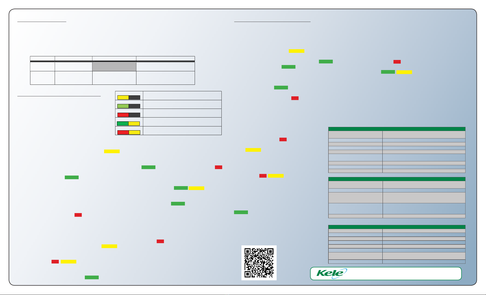
CALIBRATION GASES
Pure nitrogen zero gas and a precise mixture of oxygen and nitrogen (see Table 9) are required to calibrate the
oxygen sensor.
An orificed calibration adapter is recommended to ensure that the sensor is completely immersed in the calibra-
tion gas without applying higher than ambient pressure to it.
A complete calibration kit that includes all the required accessories in a convenient carrying case is available from
your distributor.
Type Mixture (by volume) Recommended Accuracy Comments
Zero gas Pure nitrogen if supplied from liquid source
beware of cooling the sensor.
Span gas 20.9% oxygen
balance nitrogen ± 0.1 % oxygen
Calibration gas inaccuracy adds
directly to sensor’s specified
accuracy error.
TABLE 9: Required Calibration Gases
Blinking Yellow During gas sampling period that starts immediately
when calibration is initiated.
Blinking Green Successful sampling. Waiting for user to confirm cal
gas removal.
Blinking Red Failed calibration attempt. Waiting for user to
acknowledge with either a re-try or and exit.
Green/Yellow During ambient equilibration period after successful
calibration. New calibration is applied.
Red/Yellow
During ambient equilibration period after failed
sampling. Old calibration is unchanged.
TABLE 8: Meaning of status LED blink patterns during calibration.
Kele
Manual
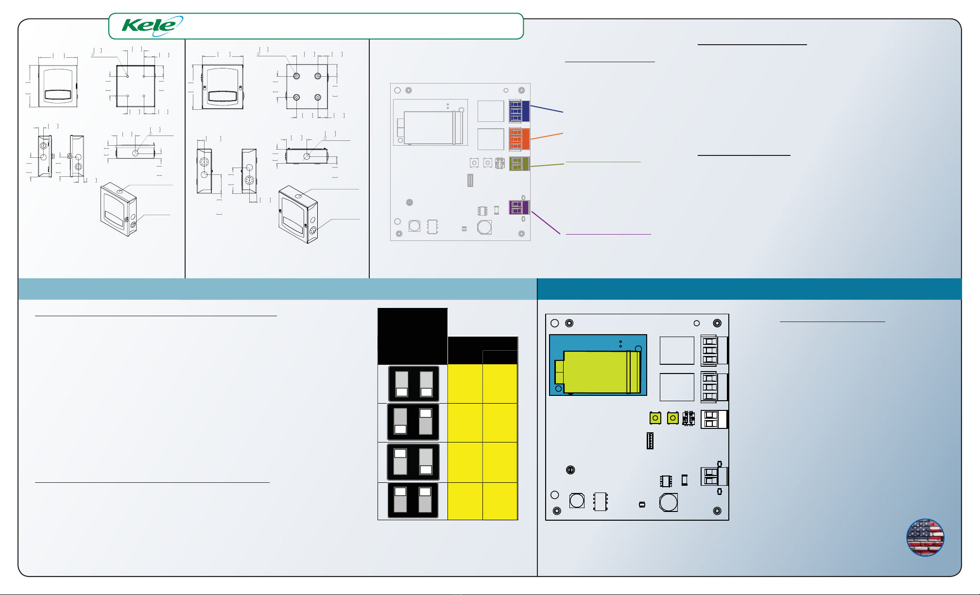
ZERO CALIBRATION PROCEDURE
The Zero calibration procedure below MUST be
done before the Span calibration.
The progress and status of the calibration process
is indicated by the color and flash-state of the
front cover status LED (see Table 8).
Apply the nitrogen (zero) calibration gas to the
sensor using a calibration adapter, following the
instructions for the calibration kit being used.
Ensure that gas is flowing to the sensor, then press
and hold the ’ZERO’ button (see Figure 9) for 3
seconds until the front cover LED starts blinking YELLOW, indicating that gas sampling is in progress.
Ensure that the calibration adapter remains correctly seated and calibration gas continues to flow for the 21.
minute sampling period.
At the end of the sampling period, the sensor’s status LED blinks GREEN if the sampling was successful or RED2.
if not.
If successful (blinking GREEN):3.
The gas sampling completed successfully. Turn off the calibration gas flow, remove the calibration•
adapter then press and hold the‘ZERO’ calibration button until the LED blinks GREEN/YELLOW indicating
that the calibration gas has been removed, the calibration has been applied and the unit is in standby
for two minutes while the sensor re-equilibrates to the ambient atmosphere before normal operation
resumes. The calibration is complete when the status LED returns to steady GREEN.
OR
If NOT successful (blinking RED):4.
The most likely cause of zero calibration sampling failure is insufficient gas flow or leaks around the cali-•
bration adapter failing to completely immerse the sensor in nitrogen. Verify that calibration gas is still
flowing at the required rate (typically about 0.2 liters per minute) and the calibration adapter is properly
positioned.
The calibration sampling can be re-started while the LED is blinking RED by again pressing and holding•
the ‘ZERO’ button until the LED blinks YELLOW, then return to step 1 above.
To exit the zero calibration routine preserving the original calibration: turn off the calibration gas flow•
and remove the calibration adapter, then press and quickly release the ‘ZERO’ button. The status LED
will blink RED/YELLOW indicating that the calibration gas has been removed, the original calibration has
been kept and the unit is in standby for two minutes while the sensor re-equilibrates to the ambient
atmosphere before normal operation resumes. The original calibration is completely restored when the
status LED returns to steady GREEN.
Industrial strength, 18 Ga. Gray powder-coated steel. Pad-lockable
hinged or screw-on cover style available.
15 – 90 %RH, non-condensing
-20 to 20°C (to minimize sensor degrada•on)
Case Dimensions (H x W x D)
Lockable hinge cover: 6.4” x 5.9” x 2.4” (163.5 x 150.8 x 60.7 mm)
Screw cover: 6.3” x 5.8” x 2.1” (160.0 x 147.3 x 52.0 mm)
Natural ven•la•on through 18, 0.1” (2.54 mm) diameter vents
Tri-color LED indicates opera•onal status of sensor.
4 trade ½” knockouts (1 per side)
4-20mA (corresponds to 0 to 25%)
Recommendedcalibrated Field-
Replaceable Sensor
KMOD-O2-25 (5 years) or KMOD-O2-50 (10 years)
14 – 30 VAC (RMS) or DC
Isolated power supply; separate transformer not required.
2 separate SPDT line-voltage-capable relays for
warning/ven•la•on and alarm outputs.
UL-rated: 10 Amps max at 120/277 VAC (RMS) or 30 VDC.
Concentration Reporting Output
Isolated, powered 4 – 20 mA current loop output.
4 mA output => 0 % concentra•on. 20 mA => 25%
Maximum loop resistance: 510
Pluggable screw-terminals for use with 12 AWG or thinner wire
SPAN CALIBRATION PROCEDURE
The Zero calibration procedure in MUST be done before the Span calibration.
The progress and status of the calibration process is indicated by the color and flash-state of the front cover status LED (see Table
8).
Apply the SPAN calibration gas to the sensor using a calibration adapter, following the instructions for the calibration kit be-1.
ing used. Ensure that gas is flowing to the sensor, then press and hold the ’SPAN’button (see Figure 9) for 3 seconds until the
status LED starts blinking YELLOW, indicating that gas sampling is in progress.
Ensure that the calibration adapter covers the sensor completely for the 2 minute sampling period. At the end of the sam-2.
pling period, the sensor’s status LED blinks GREEN if the sampling was successful or RED if not.
If successful (blinking GREEN): The sampling completed successfully. Turn off the calibration gas flow, remove the calibration3.
adapter then press and hold the‘SPAN’ calibration button until the LED blinks GREEN/YELLOW indicating that the calibration
gas has been removed, the new calibration has been applied and the unit is in standby for two minutes while the sensor re-
equilibrates to the ambient atmosphere before normal operation resumes. The calibration is complete when the status LED
returns to steady GREEN.
OR
If NOT successful (blinking RED):4.
The most likely causes of span gas sampling failure are:
Insufficient gas flow or leaks around the calibration adapter not completely immersing the sensor in the calibration gas.•
Verify that calibration gas cylinder has not run-out and the calibration adapter is properly positioned.
The oxygen concentration in the cali-•
bration gas is NOT between 20.8 and
21.0 percent (by volume).
The calibration sampling can be re-started
while the LED is blinking RED by again press-
ing and holding the ‘SPAN’ button until the LED
blinks YELLOW, then go to step 1 above.
To exit the span calibration preserving the
original calibration, press and quickly release
the ‘SPAN’ calibration button. The status
LED will blink RED/YELLOW indicating that the
calibration gas has been removed, the original
calibration will be preserved and the unit is in
standby for two minutes while the sensor re-
equilibrates to the ambient atmosphere before
normal operation resumes. The calibration is
complete when the status LED returns to steady
GREEN.