Heal Force Prince 120 Body Fat User manual

Maintenance Manual for Prince 120 Body Fat Measuring Apparatus
Page 1 of 23
Prince 120 Body Fat
Measuring Apparatus
Service Manual
Version:2008.08.01

Maintenance Manual for Prince 120 Body Fat Measuring Apparatus
Page 2 of 23
COPYRIGHT
1. Without the written permission of our company, any content of the manual
should by no means be duplicated or disclosed to any other individual or
organization.
2. Individual or organization should in no way use the manual unless authorized
by our company.
3. Our company has the sole right to change or modify this manual. Any other
individual or organization thereby should in no case change or modify the
manual.
4. Without our written permission, any organization or individual should not,
by the name of sale or donation, provide the public the manual or the
duplication of the manual.
5. Anyone who violates our copyright must be pursued according to the
copyright law.
Shanghai Lishen Scientific Equipment Co., Ltd.

Maintenance Manual for Prince 120 Body Fat Measuring Apparatus
Page 3 of 23
Table of Contents
I. Panel and functions of body fat measuring apparatus ..................................................................................... 4
II. Disassembly and maintenance of mechanical parts......................................................................................... 5
III. Steps on disassembly of body fat measuring apparatus................................................................................. 5
1. Turn the body fat measuring apparatus and unscrew 4 fittings.............................................................. 5
2. Open the lower cover:.................................................................................................................................. 6
3. Open the rear cover..................................................................................................................................... 7
4. The disassembly steps to check the bottom of upper cover...................................................................... 7
5. Bottom of backplane.................................................................................................................................... 8
IV. Introduction to circuit of body fat measuring apparatus............................................................................... 9
V. Functional description on sub-circuits:........................................................................................................... 11
1. MCU control circuit: ............................................................................................................................. 11
2. Power supply circuit:............................................................................................................................. 12
3. Sine wave generation circuit:................................................................................................................ 14
4. Differential detection circuit:................................................................................................................ 15
5. Auto calibration, diode connection, tetrode connection selection circuit: ........................................ 16
6. Crystal oscillator, key and LCD display circuit:................................................................................. 17
VI. Commissioning method and common troubleshooting................................................................................ 18
1. Commissioning condition...................................................................................................................... 18
2. Commissioning equipment.................................................................................................................... 18
3. Content and step of commissioning...................................................................................................... 18
3.1 Display commissioning ..................................................................................................................... 18
3.2 Auto shutdown and shutdown commissioing .................................................................................... 19
3.3 Commissioning on functional and accuracy test ............................................................................... 20
3.4 Commissioning on logging personal data function............................................................................ 20
3.5 Alarm commissioning........................................................................................................................ 20
3.6 Withstand test..................................................................................................................................... 20
4. Project mode............................................................................................................................................... 21
4.1 PWM differential value and standard resistance value...................................................................... 21
4.2 3V voltage and 5V voltage measurements......................................................................................... 21
5. Waveform measurement ........................................................................................................................... 22
6. Troubleshooting ......................................................................................................................................... 22
6.1 No display or missing stroke in the screen ........................................................................................ 22
6.2 Measurements of body fat rate deviates beyond ±2% ....................................................................... 22
6.3 With full illumination background after startup, it works ineffectively by pressing any key and the
apparatus is able to auto shutdown in 60sec. ........................................................................................... 22
6.4 PWM differential value and standard resistance measurements beyond the specified threshold or in
unstable condition.................................................................................................................................... 22
Maintenance Manual for Prince 120 Body Fat Measuring Apparatus
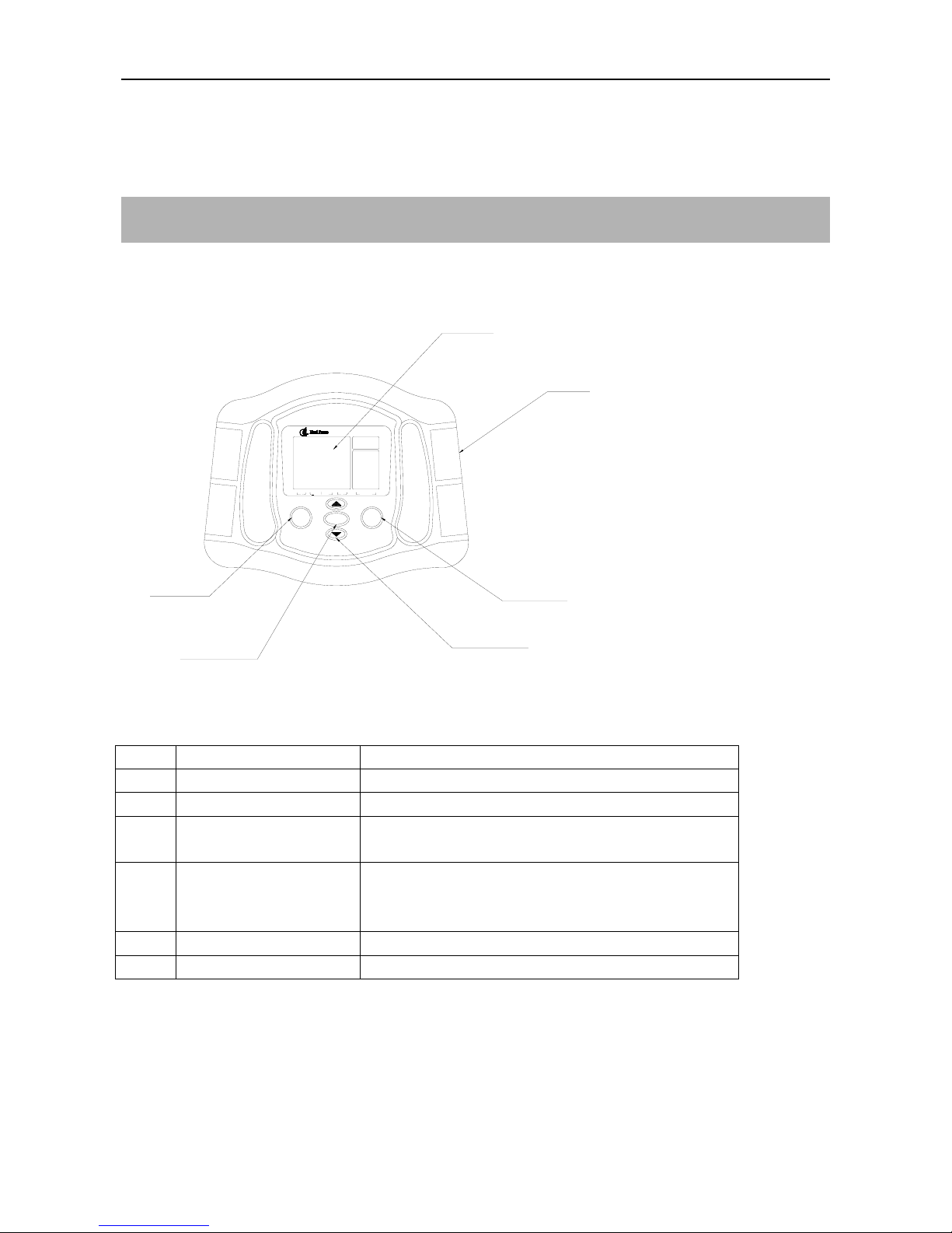
I. Panel and functions of body fat measuring apparatus
Front view of the apparatus:
6
54
3
2
1
电源
设定
测量
人体脂肪测量仪
基础
代谢
(kcal)
个人
号码
身高
体重
年龄
性别
低标准 偏高 高肥胖类型
Item Description Function
1 Electrode handle Weak detection current to be routed during test
2 Display area Display the settings and measurements
3 Test key After setting, push the key to start the test with appropriate
posture
4 Up and down keys Set the personal data (height, weight, age, sex).
Furthermore, you may select the personal code from 1 to
9.
5 Set key Set the personal code and data
6 Power key Turn on/off
Page 4 of 23

Maintenance Manual for Prince 120 Body Fat Measuring Apparatus
Page 5 of 23
II. Disassembly and maintenance of mechanical parts
Maintenance tools
Big and small Phillips
screwdriver
Nipper pliers Art knife
Big and small flat tip
screwdriver
Diagonal cutting pliers Iron, solder stick
Tweezers
Unless otherwise specified in the disassembly diagram, the installation shall be progressed in the reverse sequence
as shown in the diagram.
Components and parts shall be only replaced with those from OEM and the maintenance people must follow the
graphic directions in the manual without modification at their discretion.
Note: On reinstallation following replacement of components and parts, each screw shall be painted
with thread adhesive before being fastened.
For maintenance, the body fat measuring apparatus shall be properly placed on the robust horizontal
table.
During the assembly:
1: All components and parts shall have the surface free of score, scratch, etc.
2: During the installation, please note the assembly location and direction of each component and
part.
III. Steps on disassembly of body fat measuring apparatus
1. Turn the body fat measuring apparatus over and unscrew 4 fittings.
Table of contents
Popular Measuring Instrument manuals by other brands

Powerfix Profi
Powerfix Profi 278296 Operation and safety notes

Test Equipment Depot
Test Equipment Depot GVT-427B user manual

Fieldpiece
Fieldpiece ACH Operator's manual

FLYSURFER
FLYSURFER VIRON3 user manual

GMW
GMW TG uni 1 operating manual

Downeaster
Downeaster Wind & Weather Medallion Series instruction manual

Hanna Instruments
Hanna Instruments HI96725C instruction manual

Nokeval
Nokeval KMR260 quick guide

HOKUYO AUTOMATIC
HOKUYO AUTOMATIC UBG-05LN instruction manual

Fluke
Fluke 96000 Series Operator's manual

Test Products International
Test Products International SP565 user manual

General Sleep
General Sleep Zmachine Insight+ DT-200 Service manual


