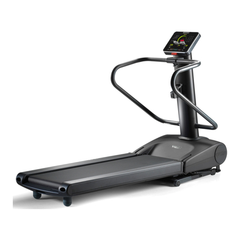
Health Care International RehabMill User manual

2
Owner’s Manual
HealthCare International, Inc.
PO Box 1509, Langley, WA 98260
P: (360) 321-7090 or (800) 398-912

3
Table of Contents
Important Safety Information
3-6
Before You Start / Machine Maintenance
Guide
7
Machine Overview
8
Accessory List
9-10
Assembly Instruction
11-21
Console Overview
22-28
Using Instruction
29
Trouble Shooting
30-32
Exploded View
33
Part List
34-36

4
Safety Precautions
This exercise equipment was designed and built for optimum safety. However,
certain precautions apply whenever you operate a piece of exercise equipment.
Be sure to read the entire manualbefore assembly and operation of this
machine.
Also, please note the following safetyprecautions:
1. Read all instructions carefully before using the machine.
2. Consult your physician or other health care professional before beginning this
or any type of exercise program.
3. Always wear proper exercise apparel whenusing the machine.
4. If at any time you feel faint, light-headed or dizzy while operating the machine,
stop exercise immediately. You should also stop exercising if you are
experiencing pain or pressure.
5. Keep children and pets away from the machine while in use.
6. Only one person can use the machine at a time.
7. Make sure your machine is correctly assembled before you use it. Be sure all
screws, nuts, and bolts are tightened prior to use and retighten periodically.
8. Do not operate this or any exercise equipment if it is damaged.
9. Keep hands and feet away from any moving parts. Do not insert any objects
into any openings.
10.Keep clothes, jewelry and loose items away from moving parts.
NOTE:
MAXIMUM WEIGHT CAPACITY FOR THE PHYSIOMILL
IS 500 LBS. (227 KGS)
WARNING:
BEFORE BEGINNING ANYEXERCISE PROGRAM CONSULT YOUR
PHYSICIAN. THIS IS ESPECIALLYIMPORTANT FOR INDIVIDUALS OVER THE
AGE OF 35 OR PEOPLE WITH PRE-EXISTING HEALTH PROBLEMS. READ
ALL INSTRUCTIONS BEFORE USING THIS FITNESS EQUIPMENT. WE
ASSUME NO RESPONSIBILITY FOR PERSONAL INJURY OR PROPERTY
DAMAGE SUSTAINED BY OR THROUGH THE USE OF THIS PRODUCT.

。
Dear Valued Customer,
Thank you for your recent purchase of the
RehabMill
from HCI Fitness. We
believe that you
have purchased one of the highestquality and affordable
rehabilitation treadmills on the
market today. Priorto using your new
RehabMill
please review the owner's manual and
product tips to maximizeyour experience.
Wishing you the best of luck in reaching your health and fitness goals!
HealthCare Internationalis
a
leadingsupplieranddistributor ofinnovativeproducts forHealth,
Wellness,
Fitness
&
Active Aging.
Visit our website
-
www.HCIFitness.com
for
information on all of our
products.
Warranty Information
(Your Serial Number is found on a white sticker at the rear base of the unit, the front of the
user manual, and on the box)
Serial #: Purchase Date:
5 Year Parts Warranty, 1 Year Labor, Lifetime Main Frame
NOTE
Before you start to assemble this unit, please note that some of the parts and screws needed
for assembly are already in place on the unit.

6
Treadmill Overview

7
Components List
PART NO.
ITEM
QTY
1
A01
Main Frame
1
PC
2
A03
Console Connecting Tube
1
PC
3
A04
Left Upright Post
1
PC
4
A05
Right Upright Post
1
PC
5
A02+F02
Display Shroud
1
SET
6
A08
Side Support Post (Long)
3
7
A09
Side Support Post (Short)
1
8
A12
Auxiliary Handrail
2
PCS
9
H01
Console/Monitor
1
PC
10
H02
Power Cord
1
PC
11
H04
Safe Key
1
PC
12
B01
TP4x12L Screw (Sliver)
6
PCS
13
B03
M5x15L Cross Head Screw (Sliver)
4
PCS
14
B04
M6x35L Cross Head Screw (Sliver)
4
PCS
15
B07
M12 x75L Round Hex Head Screw(Sliver)
4
PCS
16
B08
M8 x20L Hex Head Screw(Sliver)
6
PCS
17
B20
M10 x90 L Hex Socket Cap Screw (Sliver)
8
PCS
18
D02
Ø10.2 x Ø20 x 2.0T Washer
8
PCS
19
D03
Ø12 x Ø25 x 2.0T Washer
4
PCS
20
TOOL (5mm Allen Wrench)
1
PC

8
Assembly Instruction
First Take out all parts from the carton and check if whole qty are coincident with
Componenet List (Page 8 & 9), then place the treadmill onto flat, even floor.
Step 1:
Remove the fixed screws(B05X7) from the Motor Cover (F01),then open the Motor
Cover(F01).

9
Assembly Instruction
Step 2:
Connect Controller Wire(Middle Part) (H10) which is from the Right Upright Post
(A05) to the Controller Wire(Lower Part) (H11) which is from Bottom Support Base.
Step 3:
Insert the Left & Right Upright Post (A04&A05) into the Bottom Support Base and
make a loose connection with the following parts. DO NOT TIGHTEN ALL THE WAY
UNTIL STEP 5 –Part 3.
Qty4 –(B08) M8 x20L Hex Head Screw (Sliver)
Qty4 –(B07) M12 x75L Round Hex Head Screw (Sliver)
Qty4 –(D02) Ø10.2 x Ø20 x 2.0T Washer
Qty4 –(D03) Ø12 x Ø25 x 2.0T Washer
Foot Adjusters (E09) can help to adjust rear bottom height when the ground is
uneven.

10
Assembly Instruction
Step 4:
Attach the Console Connecting Tube (A03) to Left & Right Upright Post (A04&A05)
using the following parts to make a loose connection. DO NOT TIGHTEN ALL THE
WAY UNTIL STEP 5 –Part 3.
Qty4 –(B03) M5x15L Cross Head Screw (Sliver)

11
Assembly Instruction
Step 5:
Part 1:
Connect the Controller Wire(Middle Part) (H10) which is from the Right Upright
Post(A05) to the Controller Wire(Upper Part) (H09) wire which is out from the
backside of the Display shroud (A02).
Attach the Display Shroud (F02+A02) to the Left & Right Upright Post(A04&A05)
respectively, per the following parts .
Qty 2–(B08) M8 x20L Hex Head Screw(Sliver)
Part 2:
Now, fully tighten the Connecting Tube (A03) to the Left & Right Upright Post
(A04&A05) respectively as the diagram , per the following parts .
Qty4 –(B03) M5x15L Cross Head Screw (Sliver)
Part 3:
Then, fully tigheren the Left & Right Upright Post (A04&A05) with the Bottom
Support Base with Screws(B07)&(B08) by Allen Wrench ( as shown as below
Diagram )

12
Assembly Instruction
Step 6:
Re-Install the Motor Cover (F01) to the Main Frame (A01) with Screws (B05 X 7 ) ( as shown as
below Diagram )

13
Assembly Instruction
Step 7:
Part 1:
Connect the Extension Wire (H13) 、Controller Wire(Upper Part)(H09)、Hand Pulse Wires(H12) to
the wires respectively which are out from the backside of Console (H01) as the diagram.
Part 2:
Attach the the Monitor Support Bracket (A07) to the Cargo Holder Case Support Bracket (A02), per
the following parts .
Qty4–(B04) M6x35L Cross Head Screw (Sliver).
Part 3:
Attach the the Book Rack (F05) to Cargo Holder Case Assy (F02), per the following parts .
Qty2–(G04) Plastic Dowel Pin.

14
Assembly Instruction
Step 8:
Install the Left& Right Upright Post Bottom Collar (F03&F04) and Cargo Holder Case Assy(F02) onto
the Cargo Holder Case Support Bracket (A02) ,then Secure together with 6PCS TP4x12L Screw
(Sliver) (B01) and 2PCS Plastic Dowel Pin (G04).

15
Assembly Instruction
Step 9:
Part 1: Connect the connector which is from the Emergency Switch (H03) to the Emergency Switch
Jack (H19) wire which is out from the Control Board ( High Speed) (H17) as the diagram.
Part 2:
Install the Side Support Posts (Long&Short)(A08&A09) to two sides of the Main Frame(A01)
respectively as the diagram , per the following parts .
Qty 8 –(B20) M10 x90 L Hex Socket Cap Screw (Sliver)
Qty 8 –(D02) Ø10.2 x Ø20 x 2.0T Washer
Part 3:
a. Turn Adjustment Knob (E11) counterclockwise to loosen.
b. Pull Adjustment Knob (E11) out and adjust to your desired position as diagram
c. Re-secure the Adjustment Knob (E11) and turn clockwise until tight to remove any
looseness.
* IMPORTANT
Adjustment Knob ( E11) must be locked tightly into the holes of Side Support Post (Long & Short)
(A08&A09) as the diagram before your exercising on the machine .

16
Assembly Instruction
Step 10:
Lock two side Auxiliary Handrails (A12) into the Side Support Adjustment Posts (Long & Short)
(A10&A11) respectively as the diagram , per the following parts .
Qty 8 –(B08) M8 x20 L Hex Head Screw (Sliver)

17
Assembly Instruction
Step 11:
This machine only can be powered by using the Power Cord(H02) , please make sure
the Power Cable has already been plugged into the power jack on the front part of
the frame. (as showed on the drawing)
Congratulations! You have completed the assembly of your new Treadmill!

18
Console Overview
1. Specifications:
(1) Programs including: 1Manual, 7 preset programs, 2USER, 2HRC,and Body
Fat.
P0: Manual (field mode)
P5: Mountain
User1
P1: Plateau
P6: Rolling
User2
P2: Fat Burn
P7: Plateau
P3: Random
Hrc1
P4: Interval
Hrc2
(2) Hear Rate detection:handgrip(standard), and wireless receiver(optional).
(3) P1 ~ P7, those preset program will change the speed.
(4) Speed adjust range:
1.0km ~ 18 km; 0.6M~10M (shown on speed panel)。
(5) Incline adjust range:
0 % ~ 15%
(6) 1LCD, 7 main keys, 4 speed instant keys, 4 incline instant keys.
(7) Calories rate 1:1.
(8) Time counting may choose counting up or down.
(9) Distance function.
(10) Weight & Age personal data.
(11) Blue tooth connection with your cellular phone, or pad, compatible with
iOS/Android device, User can download APP from store, search keyword:
Delightech.
(12) Pace Steps: For estimate, provide user reference only.

19
2. LCD display: Full lighting view
3. Keys function:
Key tone: While user press any key, will beep once.
Main keys:
(1) INCLINE UP:
Increase incline; While in standby, choose program or adjust data value.
(2) INCLINE DOWN:
Decrease incline; While in standby, choose program or adjust data value.
(3) ENTER/Mode:
Choose Program; confirm the settings. Change display data.
(4) START:
Start the treadmill motor.
(5) STOP:
Pause/Stop the treadmill motor.
Hold Stop to reset the treadmill, over 2 seconds.
(6) SPEED UP:
Increase speed; While in standby, choose program or adjust data value.
(7) SPEED DOWN :
Decrease speed; While in standby, choose program or adjust data value.
Incline Instant Keys:
(1)、INCLINE 1 : Directly setting Incline to Level 3.
(2)、INCLINE 2 : Directly setting Incline to Level 6.
(3)、INCLINE 3 : Directly setting Incline to Level 9.
(4)、INCLINE 4 : Directly setting Incline to Level 12.
Speed Instant Keys:
(1)、SPEED 1: Directly setting Speed to 4KPH/ 2MPH

20
(2)、SPEED 2: Directly setting Speed to8KPH /5MPH
(3)、SPEED 3: Directly setting Speed to10KPH/6MPH
(4)、SPEED 4 : Directly setting Speed to12KPH/7MPH
4. Operating & Control:
(1)Be sure the Safety key on, open the power switch on the treadmill deck,
screen will fully display 2 seconds, and enter the standby mode.
(2)If release the Safety key, system will turn off immediately.
(3)Quick Start: when pressing the Start key, All Data use default, treadmill turn
on in 3 seconds.
(4)User also can use the arrow keys to choose the program, and setting the data,
then Start the treadmill. If user setting target data, the treadmill will stop while
data counting down to the “0”.
(5)Speed adjustment in 0.1kph/mph.
(6)Preset program per 5min. change to next time bar.
(7)Edit mode: Pulse will not appear.
(8)Pause/Edit mode, if no operating in a while, system will reset to standby
mode.
(9)Start mode: user can use arrow keys to adjust the Speed/Incline.
(10)While in standby mode, user can press start key to start exercise in Manual
program. And all data counting up.
(11)Standby mode, User can use ENTER/Mode key to setting data
(12)Settings sequence: SPEED - TIME - DISTANCE
SPEED: 1.0 –1.2 –1.4 …16.0
TIME: 0:00 –5:00 –10:00 … 95:00
DISTANCE: 0.0 –1.0 –2.0 … 99.0

21
(13)Pace Steps: Calculate the number of steps. (For estimate, provide user reference
only.)
Table of contents
Other Health Care International Treadmill manuals
Popular Treadmill manuals by other brands

strength master
strength master MX900 user manual

Keys Fitness
Keys Fitness 980HRS owner's manual
Horizon Fitness
Horizon Fitness EVOLVE 3.0 owner's manual
Reebok
Reebok Crosswalk V 7.9 Treadmill Manuel de l'utilisateur

York Fitness
York Fitness Platinum T780 instruction manual
Klarfit
Klarfit Pacemaker X3 instructions

