Healthy Climate Solutions ERV5-130 User manual

INDOOR AIR QUALITY
KIT AND ACCESSORIES
507363-04
2/2021
Supersedes 3/2020 HEALTHY CLIMATE®
ERV AND HRV VENTILATORS
INSTALLATION INSTRUCTIONS AND HOMEOWNER GUIDE FOR HEALTHY CLIMATE®
ENERGY RECOVERY VENTILATOR (ERV) AND HEAT RECOVERY VENTILATOR (HRV)
HRV5-150
HRV3-195
HRV3-150-TPD, HRV5-200-TPD,
HRV6-HEX095-TPD, HRV5-270-TPD-ECM,
ERV5-150-TPD, ERV5-175-TPD
ERV5-130
THIS MANUAL MUST BE LEFT WITH THE OWNER
FOR FUTURE REFERENCE

2
Table of Contents
Shipping and Packing List.....................................................3
General Information ...............................................................3
Model and Catalog Number
Cross-References...................................................................3
Terms and Denitions ............................................................4
Application..............................................................................4
Energy Recovery Ventilator (ERV).......................................4
Heat Recovery Ventilator (HRV)...........................................4
Required Tools and Materials................................................4
Specications .........................................................................5
Optional Fan Curve Speeds...................................................7
Dimensions - Unit - Inches (MM)...........................................8
Shaping Ducting to Fit Oval Ports......................................11
Requirements........................................................................11
Defrost Cycle (ERV/HRV).....................................................11
Recirculating Damper Defrost ............................................11
Ventilation Operational Modes for both ERV and HRV.....11
iComfort E30 (15S63) or S30 (12U67) Ventilation
Control Installation and Setup Guide.................................13
Features .............................................................................13
Installation Overview ..........................................................13
ERV and HRV Wiring diagrams..........................................14
Determining Ventilation Rate..............................................15
Ventilation Control Modes ..................................................15
Thermostat Ventilation Parameters....................................17
iComfort E30 (15S63) or S30 (12U67) Ventilation
Control User Guide...............................................................19
Ventilation Home Screen Icons..........................................19
Ventilation Settings ............................................................19
Reminders..........................................................................19
How the Dehumidistat Works..............................................19
H/C ERV/HRV Ventilation Push Button Control (Y8249) ...20
H/C ERV/HRV Deluxe Ventilation Control (Y8250).............20
H/C 20/40/60 Minute Timer (Y2169) (Optional) and
H/C Ventilation Wireless Timer (Y8251) .............................21
Using Timers ......................................................................21
H/C 20/40/60 Minute Timer (Y2169) (Optional)..................21
H/C Ventilation Wireless Timer (Y8251).............................21
Replacing the Battery.........................................................22
H/C Ventilation Wireless Repeater (Y8252)........................22
Overview of Installation Methods .......................................22
Sizing the Ductwork............................................................23
Installing Ducting Between the ERV/HRV Unit and
Living Areas in the House...................................................23
Installation Methods - Simplied (Return/Return).............24
Installation Methods - Partially Dedicated .........................25
Installation Methods - Fully Dedicated...............................26
Unit Installation Location.....................................................27
Suspending the Unit.............................................................27
Installing the ERV5-130........................................................28
Installing the Drain Connection ..........................................28
Installing Optional Plug (ERV5-150-TPD and
ERV5-175-TPD Unit Only) ....................................................28
Installing Grilles and Diffusers............................................29
Kitchen Grille......................................................................29
Round Diffuser....................................................................29
Installing Weatherhoods......................................................29
Installing Ducting from Weatherhoods to the
(ERV/HRV) Unit..................................................................29
Intake Weatherhood Requirements ...................................29
Exhaust Weatherhood Requirements ................................29
Weatherhoods....................................................................30
H/C ERV/HRV Dual Hood Kit (Y3813)..................................30
Installing H/C ERV/HRV Ventilation Push Button
Control (Y8249).....................................................................31
Installation and Operation of H/C Ventilation Wireless
Timers (Y8251)......................................................................32
Pairing ................................................................................32
Un-Pairing...........................................................................32
Installation ..........................................................................32
Installation and Pairing of H/C Ventilation Wireless
Repeaters (Y8252) ................................................................33
Installation of Wired Fan Timers.........................................33
Installation Requirements...................................................33
Operating 20/40/60 Minute Fan Timers .............................33
Lockout Mode ....................................................................33
Installation of Mechanical Timers.......................................34
Interlocking ERV/HRV Blower to Air Handler/Furnace
Blower....................................................................................34
Electrical Connections.........................................................34
Main Control Standby Setting.............................................34
Activating Dry Contact Controls..........................................35
Unit Wiring Diagrams ..........................................................36
Installer Selectable High Speed Settings...........................38
ERV/HRV Connected with an Basic and Deluxe
Control ..................................................................................38
Airow Balancing .................................................................39
Balancing Preparation........................................................39
Airow Balancing Using the Pitot Tube (All Models)...........40
Balancing Dampers............................................................40
Airow Balancing Using the Door Ports (Available on
Selected Models)................................................................41
Airow Balancing Charts.....................................................42
Sequence of Operations......................................................54
Troubleshooting ...................................................................56
Replacement Parts Summary..............................................57
Blower Assembly Service (Dealer Only) ............................58
Blower Assembly Removal.................................................58
Blower Motor Disassembly.................................................58
Blower Motor Reassembly..................................................58
Blower Assembly Installation..............................................58
Homeowner Maintenance Information ...............................59
Application Map - ERV/HRV Ventilators .............................60
3
WARNING
Improper installation, adjustment, alteration, service or
maintenance can cause property damage, personal injury
or loss of life.
Installation and service must be performed by a licensed
professional HVAC installer (or equivalent) or a service
agency.
IMPORTANT
The ERV/HRV may be used with an S30 and E30 control
system. The iComfort S30 will require a smart hub 2.0.
Do not connect the S30 or E30 to the ERV/HRV before
conrming the thermostats have 0.03.5.0XXX or higher
software.
Shipping and Packing List
Package 1 of 1 contains:
1 - Assembled ventilator
1 - Bag assembly contains the following:
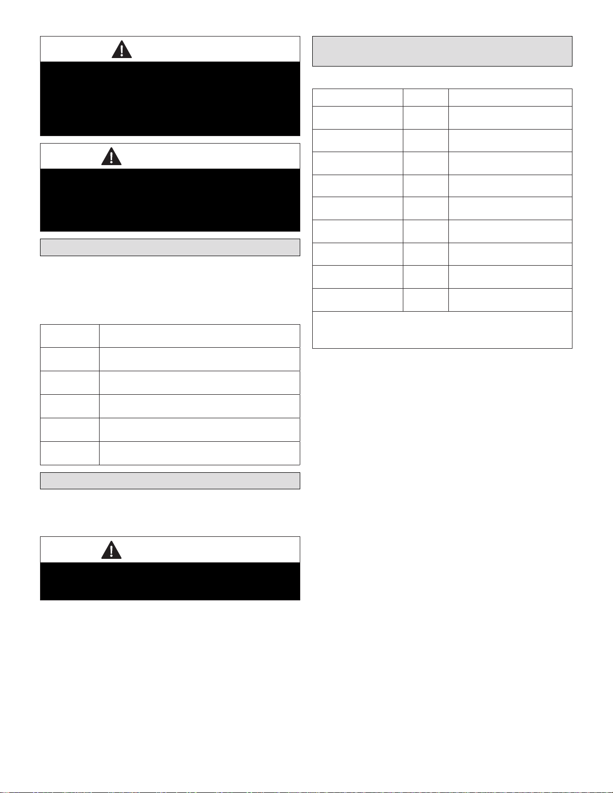
Table 1. Bag Assembly Contents
Quantity
Included Description
2Drain spout assemblies with one drain tee (included with all
models except ERV5-130)
2Drain plugs (included only with ERV5-150-TPD and ERV5-
175 -TPD)
4Mounting brackets (included only with ERV5-130)
4Hanging straps (included with all models except ERV5-130)
1Installation instruction and warranty
General Information
This instruction is intended as a general guide and does not
supersede local codes in any way. Consult authorities who
have jurisdiction before installation.
IMPORTANT
All controls referenced in this instruction are eld-
provided. Lennox catalog numbers are provide for all
reference controls.
Model and Catalog Number
Cross-References
Table 2. Models and Catalog Numbers
Model Catalog # Description
HRV3-150-TPD 17Y64 Heat Recovery Ventilation
HRV3-195-TPD Y2143 Heat Recovery Ventilation
HRV5-150 17Y58 Heat Recovery Ventilation
HRV5-200-TPD 17Y62 Heat Recovery Ventilation
HRV6-HEX095-TPD 17Y52 Heat Recovery Ventilation
HRV5-270-TPD-ECM 17Y53 Heat Recovery Ventilation
ERV5-130 17Y54 Energy Recovery
ERV5-150-TPD 17Y55 Energy Recovery
ERV5-175-TPD 17Y57 Energy Recovery
All of the above reference ERV/HRV models are compatible with iComfort S30,
Smart Hub 2.0 and E30 with rmware 3.50.xxx. Use only the catalog numbers
reference above for ordering when using either a iComfort E30 or S30 to
control the accessory.
NOTE:
If the unit is certied ENERGY STAR®, the following applies:
• This product earned the ENERGY STAR®by meeting
strict energy efciency guidelines set by Natural Re-
sources Canada and the US EPA. This product meets
ENERGY STAR®requirements only when used in Can-
ada.
• To ensure quiet operation of the ENERGY STAR®certi-
ed H/ERV, each product model must be installed using
sound attenuation techniques appropriate for the instal-
lation.
• The way your heat/energy-recovery ventilator is in-
stalled can make a signicant difference to the electri-
cal energy you use. To minimize the electricity use of
the heat/energy-recovery ventilator, a stand-alone ful-
ly ducted installation is recommended. If you choose
a simplied installation that operates your furnace air
handler for room-to-room ventilation, an electrically ef-
cient furnace that has an electronically commutated
(EC) variable speed blower motor will minimize your
electrical energy consumption and operating cost.
• Installation of a user-accessible control with your prod-
uct model will improve comfort and may signicantly re-
duce the product model’s energy use.
4
Terms and Denitions
• Defrost Mode (ERV/HRV) - to ensure reliable operation
during cold weather, the ERV/HRV will automatically cy-
cle through its defrost mode as needed.
• Dehumidistat - a control device that senses the amount
of moisture in the air and activates high−speed ventila-
tion when the air moisture level exceeds the set point.
• Reset - whenever resetting of the ERV/HRV is required,
simply unplug the power cord for 30 seconds. The Self-
Test will occur when the ERV/HRV is reconnected.
• Self-Test - each time the ERV/HRV is powered/ener-
gized, the self test function will automatically initiate.
During the self-test, the ERV/HRV will cycle through all
the speeds available (1 − 5), test the damper motor op-
eration, and will default back to the previous operational
mode and speed selection. Total self test duration is ap-
proximately 90 seconds.
• Standby Mode - the ERV/HRV is powered/energized
and waiting for fan operation to be initiated. For exam-
ple, the HRV is set to Continuous Ventilation Operation-
al Mode at speed 0.
• Thermistor - This is the temperature sensor for both
ERV and HRV that measures electrical resistance in a
known manner, as outdoor temperatures uctuate.
• HVI - Home Ventilating Institute.
• HRAI - Heating Refrigeration Air Conditioning Institute.
Application
CAUTION
As with any mechanical equipment, contact with sharp
sheet metal edges can result in personal injury. Take
care while handling this equipment and wear gloves and
protective clothing.
This equipment is designed to provide fresh air while ex-
hausting an equal amount of stale air. Refer to “Application
Map - ERV/HRV Ventilators” on page 59.
ENERGY RECOVERY VENTILATOR (ERV)
The ERV unit is equipped with an enthalpic core. The ERV
unit transfers both sensible (temperature) and latent (mois-
ture) heat from incoming fresh air to the stale air as it is
being exhausted; thus, reducing the air conditioning load.
HEAT RECOVERY VENTILATOR (HRV)
The HRV unit is equipped with an aluminum core. The de-
vice uses the stale air that is being exhausted to condition
the fresh air as it is being brought in.
Required Tools and Materials
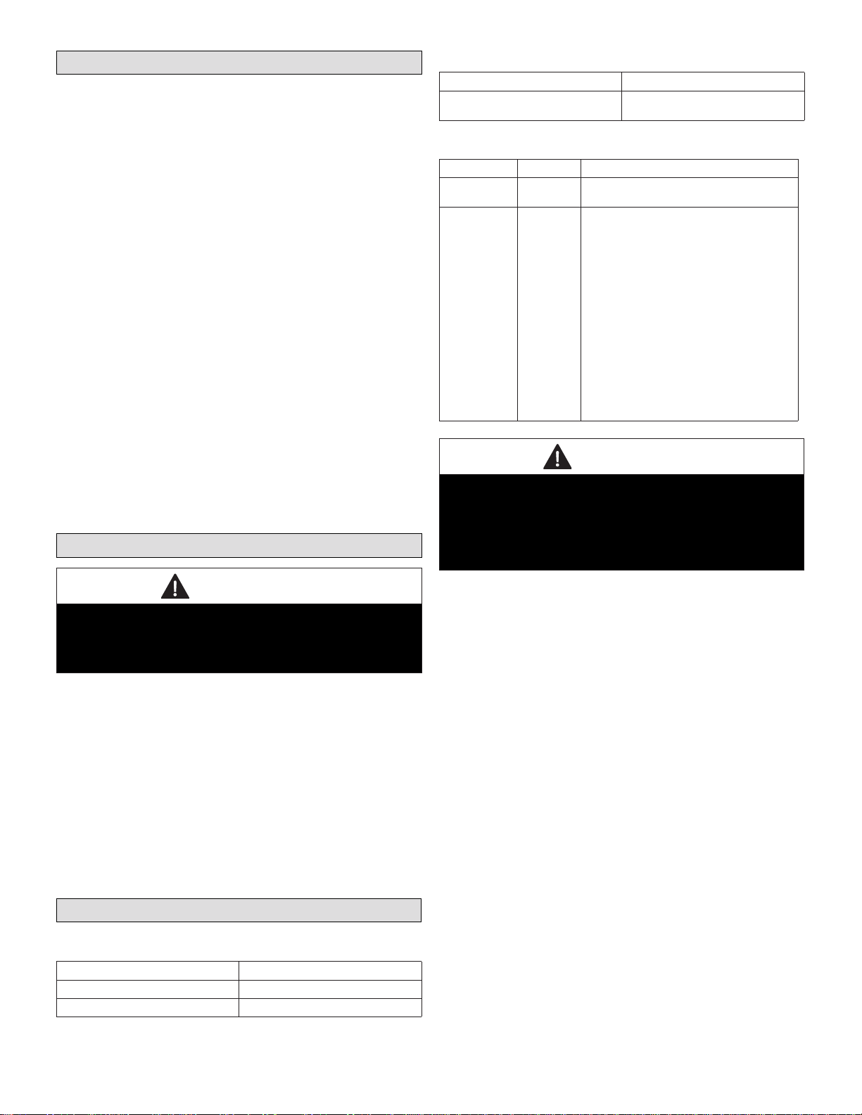
Table 3. Field-Provided Materials
Low voltage control wire Mastic tape
1/2˜ I.D. Drain hose Caulking material
Aluminum foil duct tape Zip ties (duct)
Table 3. Field-Provided Materials
Low voltage control wire Mastic tape
Fabric exible or insulated rigid ducts −
class II rated Zip ties
Table 4. Balancing Tools
Product Catalog # Description
Balancing Tool Y6484 Digital Manometer with a range of 0 - 4.000
inches w.c. (0 - 995 Pa)
H/C Door Port
Balance Kit
without Gage Y2207
Can be used to balance the following models:
HRV3-150-TPD, HRV5-200, HRV6-HEX095-
TPD, HRV5-270-TPD-ECM, ERV5-150-TPD
and ERV5-175-TPD
This kit includes:
• Two connection hoses,
• Two rubber ttings
• Instructions
Digital manometer. Will read down to 0 with
resolution of 0.001 inches w.c.(0.00024884
kPa)
or
Magnehelic® gauge - scale of 0 to 1.0 inches
w.c. (0 - to 0.24884 kPa) is not furnished and
must be eld-supplied.
CAUTION
Potential equipment malfunction or damage.
May require repairs and/or void warranty.
Do not interconnect ERV/HRV to other appliances such
as Stove Vents, Clothes Dryer Vents, Central
Vacuum Systems, Auxiliary Fans, etc.

5
Specications
Table 5. Specications
Specications Single−Core HRV Units Dual − Core
HRV Unit Single−Core ERV Units
Model No. HRV3−150−TPD
(17Y64) HRV5−150
(17Y58) HRV5-200-TPD
(17Y62) HRV6-HEX095-
TPD (17Y52) HRV5-270-TPD-
ECM
(17Y53)
HRV3−195
(Y2143) ERV5-130
(17Y54) ERV5-150-TPD
(17Y55) ERV5-175-TPD
(17Y57)
Energy Star®
certied
(Canada Only)
No No No
These products earned the ENERGY STAR® by meeting strict energy efciency guidelines set by Natural Resources Canada and the US EPA. These
products meets ENERGY STAR®requirements only when used in Canada.
Unit Weight
in pounds
(kilograms) 45 (20) 62 (28) 58 (26) 59 (27) 59 (27) 82 (37) 41 (19) 42 (19) 54 (24)
Unit
Dimensions Refer to dimension drawings starting with “Figure 1. Dimensions and Airows” on page 7.
*High Speed (HVI Certied)
inches w.g. (Pa) CFM (L/s) CFM (L/s) CFM (L/s) CFM (L/s) CFM (L/s) CFM (L/s) CFM (L/s) CFM (L/s) CFM (L/s)
0.1 (25) 170 (80) 170 (80) 203 (96) 110 (52) 280 (132) 222 (105) 133 (63) 161 (76) 195 (92)
0.2 (50) 155 (73) 159 (75) 193 (91) 104 (49) 273 (129) 210 (99) 129 (61) 155 (73) 184 (87)
0.3 (75) 148 (70) 148 (70) 182 (86) 97 (46) 267 (126) 195 (92) 125 (59) 146 (69) 172 (81)
0.4 (100) 136 (64) 140 (66) 172 (81) 89 (42) 261 (123) 176 (83) 123 (58) 138 (65) 161 (76)
0.5 (125) 125 (59) 125 (59) 159 (75) 81 (38) 254 (120) 157 (74) 119 (56) 127 (60) 150 (71)
0.6 (150) 114 (54) 148 (70) 72 (34) 248 (117) 133 (63) 112 (53) 117 (55) 140 (66)
0.7 (175) 102 (48) 136 (64) 61 (29) 242 (114) 108 (51) 108 (51) 104 (49) 129 (61)
0.8 (200) 89 (42) 121 (57) 49 (23) 235 (111) 83 (39) 102 (48) 93 (44) 117 (55)
0.9 (225) 76 (36) 108 (51) 227 (107) 57 (27) 95 (45) 83 (39) 106 (50)
1.0 (250) 57 (27) 93 (44) 220 (104) 87 (41) 74 (35) 93 (44)
*Adjusted
Sensible
Recovery
Efciency
@ 32 °F (0ºC)
@ 66 CFM
(31 L/s) 68% @ 64 CFM
(30 L/s) 82% @ 64 CFM
(30 L/s) 82% @ 64 CFM
(30 L/s) 79% @ 64 CFM
(30 L/s) 77% @ 64 CFM
(30 L/s) 87% @ 64 CFM
(30 L/s) 77% @ 64 CFM
(30 L/s) 82% @ 66 CFM
(31 L/s) 85%
*Sensible
Recovery
Efciency
@ 32 °F (0ºC)
@ 66 CFM
(31 L/s) 61% @ 64 CFM
(30 L/s) 75% @ 64 CFM
(30 L/s) 76% @ 64 CFM
(30 L/s) 75% @ 64 CFM
(30 L/s) 75% @ 64 CFM
(30 L/s) 81% @ 64 CFM
(30 L/s) 72% @ 64 CFM
(30 L/s) 75% @ 66 CFM
(31 L/s) 75%
*Adjusted
Sensible
Recovery
Efciency
@ -13 °F
(−25ºC)
@ 76 CFM
(36 L/s) 65% @ 69 CFM
(33 L/s) 76%
@ 102 CFM (48
L/s) 73%
@ 68 CFM
(31 L/s) 68% @ 70 CFM
(33 L/s) 71% @ 114 CFM
(54 L/s) 70% N/A @ 70 CFM
(33 L/s) 64%
@ 68 CFM
(32 L/s) 62%
*Sensible
Recovery
Efciency
@ -13 °F
(−25ºC)
@ 76 CFM
(36 L/s) 61% @ 69 CFM
(33 L/s) 72%
@ 102 CFM (48
L/s) 70%
@ 68 CFM
(31 L/s) 65% @ 70 CFM
(33 L/s) 70% @ 114 CFM
(54 L/s) 68%
@ 53 CFM
(25 L/s) 54% @ 70 CFM
(33 L/s) 60%
@ 68 CFM
(32 L/s) 58%
*Latent
Efciency
95ºF (35ºC) N/A N/A N/A N/A N/A N/A @ 64 CFM
(30 L/s) 38% @ 66 CFM
(31 L/s) 43% @ 64 CFM
(30 L/s) 41%
*Total
Efciency
95ºF (35ºC) N/A N/A N/A N/A N/A N/A @ 64 CFM
(30 L/s) 44% @ 66 CFM
(31 L/s) 48% @ 64 CFM
(30 L/s) 48%
* Certied by the Home Ventilating Institute (HVI) according to test procedures developed by HVI members and based on internationally recognized standards. For
performance ratings at other conditions not shown, please visit the HVI website.
Number
of speeds
available with
S30/E30 and
basic wall
control
222222222
6
Table 5. Specications
Specications Single−Core HRV Units Dual − Core
HRV Unit Single−Core ERV Units
Model No. HRV3−150−TPD
(17Y64) HRV5−150
(17Y58) HRV5-200-TPD
(17Y62) HRV6-HEX095-
TPD (17Y52) HRV5-270-TPD-
ECM
(17Y53)
HRV3−195
(Y2143) ERV5-130
(17Y54) ERV5-150-TPD
(17Y55) ERV5-175-TPD
(17Y57)
Number
of speeds
available with
optional wall
control
555555555
Ventilator Type Heat
Recovery Heat
Recovery Heat
Recovery Heat
Recovery Heat
Recovery Heat
Recovery Energy
Recovery Energy
Recovery Energy
Recovery
Heat/Energy
Recovery Core Aluminum Aluminum Aluminum Aluminum Aluminum Aluminum Enthalpic Enthalpic Enthalpic
Number of ERV/
HRV Cores 111112111
Defrost Type Recirculating Recirculating Recirculating Recirculating Recirculating Damper Recirculating Recirculating Recirculating
Door Port
Balancing Yes Yes Yes Yes Yes No No Yes Yes
Balancing
Damper in
Supply &
Exhaust Collar Yes Yes Yes Yes Yes No No Yes Yes
Number of Ports 444445444
Pre-Filters
Supply &
Exhaust
MERV6 or MERV13**
** To be ordered separately. Comes in a set of 4 and is installed in the Fresh Side only. When a MERV 13 lter is installed for the rst time, airow will
need to be balanced (see “Airow Balancing” on page 38 for further details).
Wall Controller
Included No No No No No No No No No
Condensate
Drain
Connections:
Spouts: qty. 2
(1/2” o.d.)
Drain Tee: qty. 1
(1/2” o.d.)
Yes Yes Yes Yes Yes Yes No Yes Yes
Drain Plug
Included No No No No No No No Yes Yes
Hanging Strap
kit Included Yes Yes Yes Yes Yes Yes No Yes Yes
Bracket
Included No No No No No No Yes No No
Electrical Characteristics: 120 Volts, 60 Hertz, 1 phase
Fan HP 1/20 1/10 1/10 1/10 1/10 1/10 1/10 1/20 1/20
Motor Type PSC PSC PSC PSC ECM PSC PSC PSC PSC
Fan Watts −
High Speed
@HVI Test
SRE max rated
CFM**
140 119 92 46 44 93 86 102 96
Fan Watts − Low
Speed
@HVI Test SRE
min rated CFM* 74 71 60 32 22 66 48 66 62
Amp Rating 1.2 1.4 1.4 0.5 2.1 1.5 1.4 1.7 1.4
* Certied by the Home Ventilating Institute (HVI) according to test procedures developed by HVI members and based on internationally recognized standards. For
performance ratings at other conditions not shown, please visit the HVI website.

7
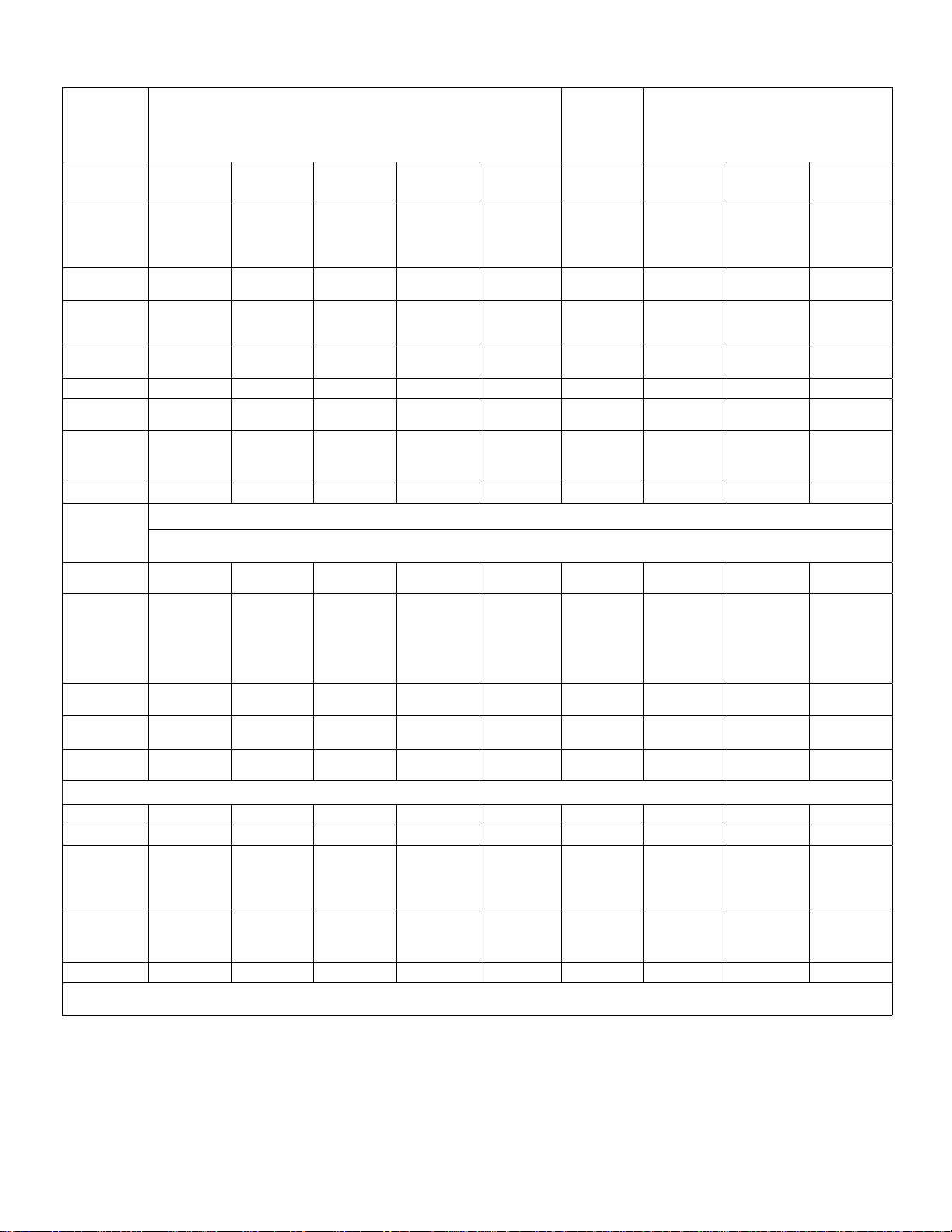
Optional Fan Curve Speeds
Table 6. Optional Fan Curves Speeds (Factory Tested)
NOTE: All specications are subject to change without notice.
Single−Core HRV Units Dual−Core
HRV Units Single−Core ERV Units
Model No. HRV3−150−
TPD
(17Y64)
HRV5−150
(17Y58) HRV5-200-
TPD
(17Y62)
HRV6-
HEX095-TPD
(17Y52)
HRV5-270-
TPD-ECM
(17Y53)
HRV3−195
(17Y65) ERV5-130
(17Y54) ERV5-150-
TPD
(17Y55)
ERV5-175-
TPD
(17Y57)
Speed 4 − Medium High
inches w.g.
(Pa) CFM L/s CFM L/s CFM L/s CFM L/s CFM L/s CFM L/s CFM L/s CFM L/s CFM L/s
0.1 (25) 129 61 153 72 189 89 98 47 249 120 167 78 117 56 127 61 150 71
0.2 (50) 119 56 141 67 170 80 95 46 239 115 159 75 112 54 119 57 138 66
0.3 (75) 110 52 131 62 153 72 89 43 228 110 150 71 110 53 112 54 123 59
0.4 (100) 101 48 117 55 136 64 80 38 217 104 140 66 105 50 105 50 112 54
0.5 (125) 91 43 96 45 120 57 70 34 204 98 124 58 98 47 96 46 101 49
0.6 (150) 82 39 80 38 106 50 60 29 190 91 110 52 95 46 89 43 88 42
0.7 (175) 69 33 91 43 176 84 93 44 88 42 80 38 74 36
0.8 (200) 60 28 78 37 160 77 80 38 62 30
Speed 3 − Medium
0.1 (25) 114 54 144 68 161 76 95 46 209 100 142 67 100 48 100 48 128 60
0.2 (50) 105 50 130 61 141 67 90 43 198 95 136 64 96 46 98 47 115 55
0.3 (75) 92 43 120 57 123 58 80 38 185 89 127 60 92 44 90 43 101 49
0.4 (100) 82 39 106 50 108 51 72 35 171 82 118 55 89 43 82 39 90 43
0.5 (125) 71 34 88 42 92 43 60 29 155 74 103 48 84 40 75 36 75 36
0.6 (150) 60 28 77 36 137 66 92 43 80 38 64 31 63 30
0.7 (175) 64 30 118 57 72 34 75 36 50 24
0.8 (200) 52 25 97 46
Speed 2 − Medium Low
0.1 (25) 90 42 127 60 127 60 88 42 158 76 115 54 n/a n/a n/a n/a 102 48
0.2 (50) 81 38 116 55 108 51 80 38 142 68 107 50 n/a n/a n/a n/a 89 42
0.3 (75) 70 33 106 50 90 42 70 34 123 59 100 47 n/a n/a n/a n/a 75 36
0.4 (100) 60 28 97 46 73 34 18 29 101 48 90 42 n/a n/a n/a n/a 60 29
0.5 (125) 46 22 86 40 60 28 75 36 81 38 n/a n/a n/a n/a 47 23
0.6 (150) 48 23 45 22 66 31 n/a n/a n/a n/a
0.7 (175) 38 18 n/a n/a n/a n/a
0.8 (200) n/a n/a n/a n/a
Speed 1 − Low
0.1 (25) 76 36 108 51 100 48 70 34 106 51 88 41 63 30 66 32 74 35
0.2 (50) 61 29 100 47 78 37 58 28 79 38 80 38 60 29 60 29 61 29
0.3 (75) 49 23 91 43 60 28 45 22 45 22 73 34 57 27 54 26 48 23
0.4 (100) 35 17 78 37 46 22 36 17 63 30 53 25 45 22 35 17
0.5 (125) 32 15 56 26 50 24 37 18
0.6 (150) 43 20 44 21
0.7 (175)
0.8 (200)

8
Dimensions - Unit - Inches (MM)
HRV5-150 HEAT RECOVERY VENTILATORS
18-3/4 (476)
NOTE - Front clearance of
25 in. (635 mm)
is recommended
for servicing unit
14-3/4 (375)
HRV3-195 HEAT RECOVERY VENTILATORS
14-3/4 (375)
NOTE - Front clearance of
25 in. (635 mm)
is recommended for
servicing unit
NOTE: DRAWING DEPICTS HRV3-300; MODEL
HRV3-195 MOTOR IS AT TOP BLOWER
DEFROST
DAMPER DEFROST AIR
FROM INSIDE
FILTER
CONDENSATE DRAINS
FRESH
AIR TO
INSIDE
STALE AIR
FROM
INSIDE
BLOWER
FRESH
AIR FROM
OUT SIDE
MOTOR (SEE
NOTE BELOW)
CORE
FILTER
CORE
STALE
AIR TO
OUTSIDE
49 (1245)
BLOWER
Blower Duct
Connections
7 in. (178 mm)
Duct
Connections
6 in. (152 mm)
RECIRCULATING
DEFROST
DAMPER
FILTERS
STALE AIR FROM INSIDE
CONDENSATE
DRAINS BALANCING
DAMPER
FRESH
AIR TO
INSIDE
STALE
AIR TO
OUTSIDE
NOTE - All Duct Connections
6 in. (152 mm)
FRESH AIR FROM OUTSIDE
MOTOR
BALANCING DAMPER
33-5/8 (854)
BLOWER
BLOWER
CORE
HRV3-150-TPD and ERV5-150-TPD
FRESH AIR
FROM
OUTSIDE
STALE
AIR FROM
INSIDE
FRESH
AIR TO
INSIDE
STALE
AIR TO
OUTSIDE
DEFROST
DAMPER
(TPD Model Only)
BLOWER BLOWER
NOTE − Front clearance of
25 inches (635 mm) is
recommended for servicing unit
14
(356)
17-1/4
(438)
All duct connections are oval collars
for use with 5 in. (125 mm) ductwork.
Balancing Dampers are located on all collars.
22-3/4
18-3/4 (476)
Figure 1. ERV5-150-TPD, HRV3-150-TPD, HRV3-195 AND HRV5-150

9
18-3/4
(476)
All duct connections are oval collars for use with 6 in. (150 mm) ductwork,
balancing dampers are located on all collars.
BLOWER NOTE − Front clearance of
25 in. (635 mm) is
recommended for servicing unit
15-1/2
33-5/8 (854)
FRESH AIR
FROM
OUTSIDE
STALE
AIR FROM
INSIDE
FRESH
AIR TO
INSIDE
STALE
AIR TO
OUTSIDE
RECIRCULATING
DEFROST
DAMPER
CONDENSATE
DRAINS
CORE
FILTERS
BLOWER
Figure 2. ERV-175-TPD, HRV5-200-TPD AND HRV5-270-TPD-ECM
17 1/4 in (438 mm)
in (3 mm)
Front View
Top View
Fresh
Air From
Outside
Stale
Air To
Outside
Fresh
Air To
Inside
Stale
Air From
Inside
Motorized
Impeller
CondensateDrains
Removable
Heat Recovery
Core
Recirculating
Defrost Damper
Filter
25-3/4 (654)
NOTE: Front clearance of 25” (635mm) is
recommended for servicing unit. All duct
connections are oval collars for use with 6 in.
(125 mm) ductwork Balancing dampers are
located on all collars.
Figure 3. HRV6-HEX095-TPD
10
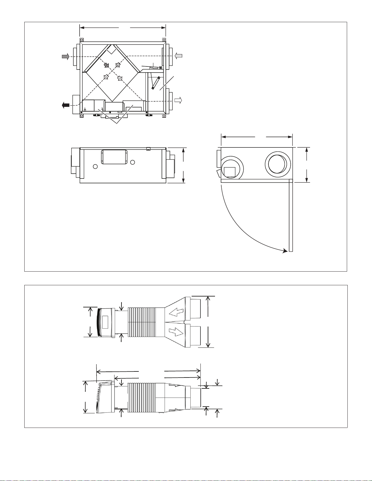
FRESH AIR
FROM OUTSIDE
STALE AIR
TO OUTSIDE
FRESH AIR
TO INSIDE
STALE AIR
FROM INSIDE
19-3/8
(492)
9-3/4
(248)
NOTE − Front clearance of
25 In. (636 mm) is recommended
for servicing unit
25-3/4
(654)
All duct connections are oval collars for use with 5 in. (150 mm) ductwork.
9-3/4
(248)
MOTORIZED
IMPELLERS
CORE
FILTERS
DEFROST
DAMPER
Figure 4. ERV5-130
8-1/4 (210)
13 (330)
25 (635)
8 (203)
6 (152)
21-1/2 (546)
TOP VIEW
SIDE VIEW
6 (152)
5 (127)
6 (152)
Compatible with 5” or
6” diameter duct.
Figure 5. Dual Hoods
11
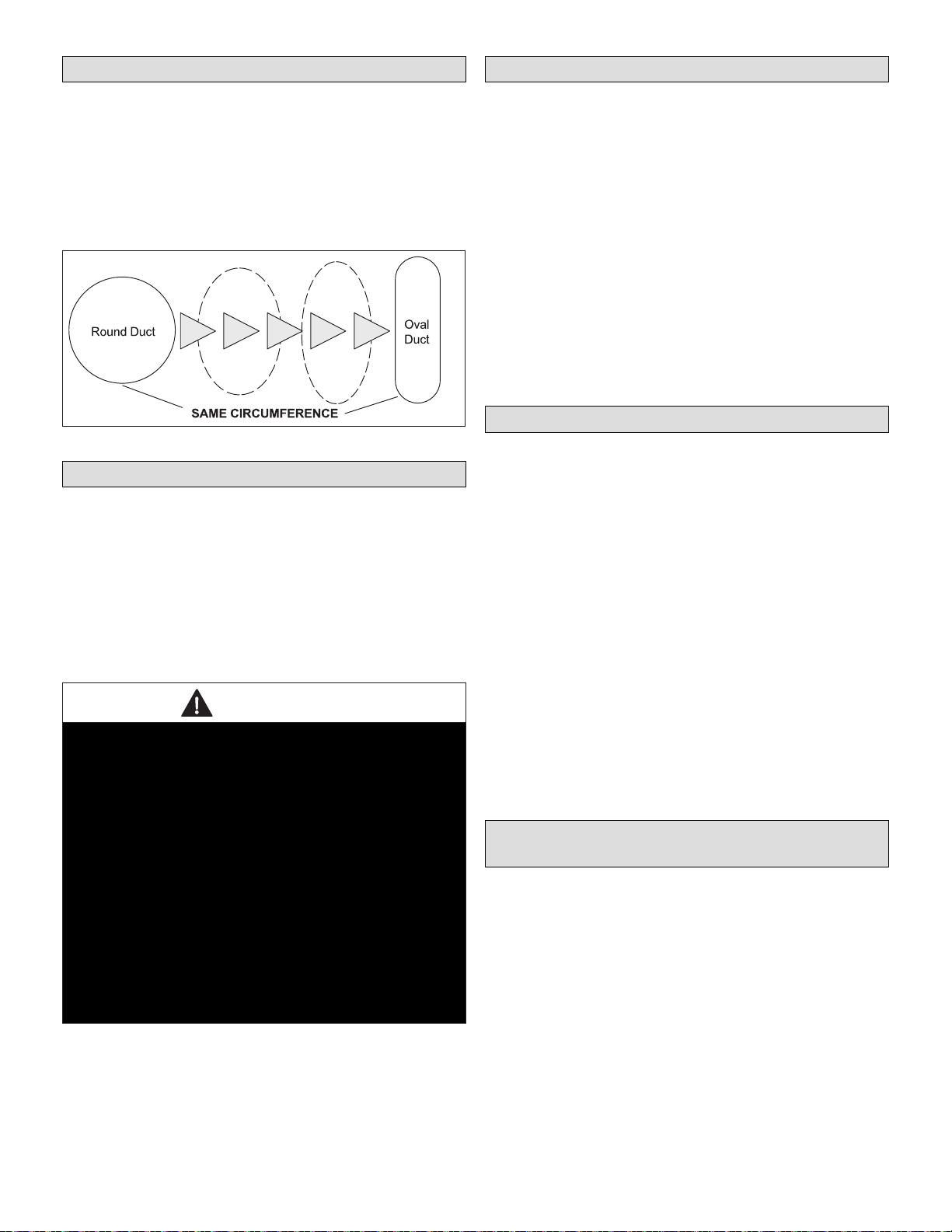
Shaping Ducting to Fit Oval Ports
Applicable Units:
HRV3-150-TPD, HRV5-200-TPD, HRV6-HEX095-TPD, HRV5-270-
TPD-ECM, ERV5-150-TPD and ERV5-175-TPD
These units have oval supply and return ports. This enables
these units to be as space efcient as possible. Circumfer-
ence of the port remains the same as round ducting. Simply
bend a standard duct tting to the correct shape and attach
to the oval port using the same method as for a round port.
Figure 6. Shaping Ducting to Fit Oval Ports
Requirements
The following appliances should not be connected to the
ERV/HRV unit:
• Clothes dryer
• Range top
• Stove top fan
• Central vacuum system
NOTE:Failure to follow this instruction will void the ERV/
HRV unit warranty.
DANGER
Risk of Carbon Monoxide Poisoning and/or Explosion.
Can cause injury or death.
Combustion and ue gases from heating appliances must
never be allowed to enter living spaces.
ERV/HRV unit must be properly balanced (see page 30
or 32) to prevent negative pressure in structure. Negative
pressure can cause back−drafting of combustion gases
in other household appliances such as Gas Furnaces, Oil
Furnaces, Hot Water Heaters, Wood Stoves, Fireplaces,
etc.
(5-Port HRV models only) Defrost cycles will cause
negative pressure in equipment room. Install ductwork
and route to areas that do not contain appliances with
vented combusted gases. Never connect a return or
supply duct to other heating units such as replaces,
wood stoves.
Defrost Cycle (ERV/HRV)
The ERV/HRV has an electronically controlled defrost sys-
tem. The defrost cycle is activated when the outdoor tem-
perature drops below 27ºF (−3ºC). Incoming fresh air is
measured to set the defrost times and the run times while in
the defrost mode. The three defrost settings are:
• At 27ºF (−3ºC) ERV/HRV runs in defrost for three min-
utes and runs in ventilation for 25 minutes
• At −4ºF (−20ºC) ERV/HRV runs in defrost for 4.5 min-
utes and runs in ventilation for 17 minutes
• At −31ºF (−35ºC) ERV/HRV runs in defrost for 7 min-
utes and runs in ventilation for 15 minutes
No remote device can override this defrost mode or se-
lected speed until the cycle is complete. After the cycle is
completed the ERV/HRV defaults to previous settings. If the
cycle is completed and the thermistor continues to measure
defrost temperature the defrost cycle is repeated.
Recirculating Damper Defrost
Applicable Units:
HRV3−150−TPD, HRV5−150, HRV5-200-TPD, HRV6-HEX095-TPD,
HRV5-270-TPD-ECM, ERV5-150-TPD, ERV5-175-TPD and ERV5-130)
During defrost a motor driven damper door mechanism
closes off the supply air from outside allowing exhaust air to
recirculate through the unit’s core. During defrost cycle no
ventilation is occurring. After the defrost period, the damp-
er operates in the opposite direction to reopen the fresh
air port. Defrost cycle repeats until the temperature rises
above 27ºF (−3ºC).
Damper Defrost − Five Port Model (HRV3−195) - During
defrost a motor driven damper door mechanism closes off
the supply air from outside allowing a fth port to open en-
abling warm air to be drawn in from around the unit. During
defrost cycle stale air exhaust is still occurring.
After the defrost period, the damper operates in the oppo-
site direction to reopen the fresh air port.
Defrost cycle re-peats until the temperature rises above
27ºF (−3ºC). (The defrost port can also be ducted to anoth-
er location.)
Ventilation Operational Modes for both ERV
and HRV
Today’s modern, air tight homes require fresh outdoor air to
maintain a healthy indoor air environment. The amount of
ventilation required in a home depends upon:
• The number of occupants and their activity levels
• The way the home was built
• Personal preferences for air
The ERV/HRV introduces fresh air to your home while re-
covering energy from the air it exhausts. Specically, an
ERV/HRV that is properly installed, operated, and main-
tained will:
• Exhaust stale and contaminated air
• Introduce an equal amount of fresh outdoor air

12
• Recover the majority of the energy from the exhausted
stale air
• Use the recovered energy to pre-heat or pre-cool out-
side air that is drawn into the house
• Distribute the fresh air throughout the house
How much ventilation is needed?
During seasons when windows and doors are closed (win-
ter and summer, if air conditioned) the ERV/HRV should be
set to operate continuously on low speed with the option of
going to high speed as the need arises. For example, if a
large number of people are present in the home, the unit
should be switched temporarily to high speed. Conversely,
when the home is unoccupied, an intermittent operational
mode (e.g. 20 minutes on / 40 minutes off) may be used.
Selecting the Ventilation Rate That is Right for You.
The modes of operation and speeds are used to adjust your
indoor ventilation rate. Experiment with the ventilation lev-
els in your home to evaluate the ideal amount of ventilation
to suit your home and personal preferences. Operational
modes available to you will depend on the main control that
is installed. Some features and modes may be unavailable
to you.
Table 7. Operational Modes
Mode Icon Description
Continuous
Ventilation
This mode of operation provides
continuous ventilation within the
home. You may, for example, select
Continuous Ventilation at low speed
for normal operation and increase
to high speed during increased
activity levels, such as cooking and
showering, etc.
20 Minutes
On, 40
Minutes
Recirculation*
This mode ventilates for 20 minutes
and circulates the household air for
40 minutes each hour. This mode is
not applicable if your HRV is con-
nected to a forced air system. This
mode is useful when “Continuous
Ventilation” mode is providing too
much ventilation.
20 Minutes
On, 40
Minutes
Standby*
This mode of operation provides 20
minutes of ventilation each hour.
You can use this ventilation mode
at low speed for low household
activity levels or when the home is
unoccupied. This mode is useful if
“Continuous Ventilation” mode is
providing too much ventilation.
10 Minutes
On, 50
Minutes
Standby*
This mode of operation provides 10
minutes of ventilation each hour.
You can use this ventilation mode at
low speed for low household activity
levels or when the home is unoccu-
pied. This mode is useful if “20 Min-
utes On, 40 Minutes Standby” mode
is providing too much ventilation.
Continuous
Recirculation*
This mode continuously recirculates
your household air (no ventilation).
This mode is not applicable if your
HRV is connected to a forced air
system.
Continuous
Low Fan
Speed
This mode will operate the fan in
low speed continuously at the se-
lected operating mode (Ventilation
or Recirculation).
Table 7. Operational Modes
Mode Icon Description
Continuous
High Fan
Speed
This mode will operate the fan in
high speed continuously at the se-
lected operating mode (Ventilation
or Recirculation). This mode is HI
useful when occupancy or activity
levels in the home is high for an
extended period of time.
Recirculation
Recirculates existing household air
without introducing fresh air. Recir-
culation modes (II and V) are not
applicable if your HRV is connected
to a forced air system, since your
forced air system already circulates
the household air. Recirculation
modes are unavailable on some
models.
* This mode of operation is only available on the Digital 5 Speed / 5 Mode
Control (Y8250).
13
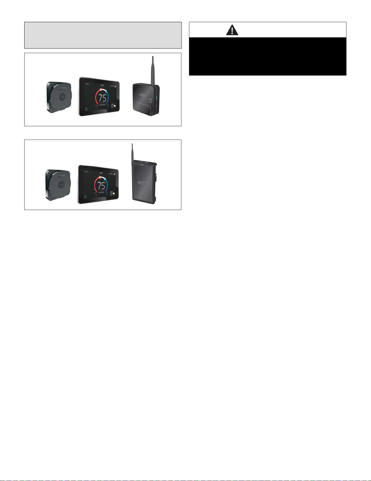
iComfort E30 (15S63) or S30 (12U67)
Ventilation Control Installation and Setup
Guide
Figure 7. iComfort S30 with Smart Hub 2.0
Figure 8. iComfort E30
All of the models reference in “Table 2. Models and Catalog
Numbers” on page 3 are compatible with iComfort S30
using the Smart Hub 2.0 or E30.
IMPORTANT
The ERV/HRV may be used with an S30 and E30 control
system. The S30 will require a 2.0 smart hub,
Do not connect the S30 or E30 to the ERV/HRV before
conrming the thermostats have 03.50.XXX or higher
software.
FEATURES
The E30 or S30 can operate the ERV or HRV in the follow-
ing modes:
• ASHRAE 62.2 compliant mode.
• Non-ASHRAE compliant mode - Environmental over-
rides uses outdoor temperature and outdoor dew point
within a set parameter range.
• Timed mode - Runs ventilation equipment for a timed
amount per hour.
• User demanded ventilation.
• Provides ventilation for zoned and non-zoned applica-
tions.
INSTALLATION OVERVIEW
• Refer to “ERV and HRV Wiring diagrams” on page 14
for wiring connections.
• For installer information concerning ventilation rates
and ventilation rates, thermostat ventilation control pa-
rameters, see the following sections.
• For end user information go to “iComfort E30 (15S63)
or S30 (12U67) Ventilation Control User Guide” on page
19.
• Additional help and on-line tutorials are also available
on the iComfort support page at:
http://www.support.lennoxicomfort.com/help/index.html

14
ERV AND HRV WIRING DIAGRAMS
Use the applicable wiring diagram to connect your ventila-
tion equipment.
IMPORTANT
Interlocking is NOT required on ventilation equipment
when controlled by either an iComfort E30 or S30
thermostat.
12
VDC
+ -
COM
BUS
A B
ACC1 ACC2
Non-Communicating
Indoor Unit
2
3
12
VDC
- +
COM
BUS
B A
MAG-MOUNT
LOW
ON
RED
YEL
GRN
HI
COM
NO
NC
BLK
HRV/ERV
Terminal Block
1
Two Speed ERV / HRV Wiring
Low and High Speed
iComfort E30
12
VDC
+ -
COM
BUS
A B
ACC1 ACC2
Non-Communicating
Indoor Unit
2
3
3Wiring connections between E30 and
non-communicating indoor unit will be
application specific.
12
VDC
- +
COM
BUS
B A
MAG-MOUNT
LOW
ON
RED
YEL
GRN
HI
COM
NO
NC
BLK
HRV/ERV
Terminal Block
1
Single Speed ERV / HRV Wiring
High Speed
iComfort E30
1Wire Jumper required between ON
and RED terminals.
2For two speed units, ACC1 is low speed andACC2 is
high speed.
1Wire Jumper required between ON and RED terminals.
2ACC1 is high speed for single speed units.
3Wiring connections between E30 and non-communicating
indoor unit will be application specific.
Figure 9. iComfort E30 to Ventilation Equipment
Wiring Connections
12
VDC
+ -
COM
BUS
A B
ACC1 ACC2
iComfort S30 with
Smart Hub 2.0
2
1Wire Jumper required between ON and RED terminals.
2For two speed units, ACC1 is low speed andACC2 is high speed.
12
VDC
- +
COM
BUS
B A
MAG-MOUNT
LOW
ON
RED
YEL
GRN
HI
COM
NO
NC
BLK
HRV/ERV
Terminal Block
1
12
VDC
+ -
COM
BUS
A B
ACC1 ACC2
Lennox Communicating
Indoor Unit
iComfort S30 with
Smart Hub 2.0
2
1Wire Jumper required between ON and RED terminals.
2ACC1 is high speed for single speed units.
12
VDC
- +
COM
BUS
B A
MAG-MOUNT
LOW
ON
RED
YEL
GRN
HI
COM
NO
NC
BLK
HRV/ERV
Terminal Block
1
Single Speed ERV / HRV Wiring
High Speed
Two Speed ERV / HRV Wiring
Low and High Speed
Lennox Communicating
Outdoor Unit
Lennox Communicating
Indoor Unit
Lennox Communicating
Outdoor Unit
Figure 10. iComfort S30 to Ventilation Equipment
Wiring Connections

15
DETERMINING VENTILATION RATE
The following information is used to set both the timed or
ASHRAE compliant high and low speed ventilation rate for
ERVorHRVsingleandtwo-speedunitswhenusingeitherthe
iComfort E30, M30 or S30 thermostats.
Thermostat ventilation CFM parameters are to be adjusted
only after the HRV/ERV set up is completed and the CFMs
are known. Once the thermostat’s CFMs are adjusted they
are used with the thermostat’s timer algorithm to determine
how long to run the HRV/ERV and to change from low to
high speed if a 2-stage HRV/ERVs.
See “Installer Selectable High Speed Settings” on page
37 for conguring CFM on the ERV / HRV equipment.
Ventilation Rate for High Speed
When using ERV/HRV as a single or two speed units you
must set the blower to the highest speed to balance airow
to be ASHRAE 62.2 compliant.
• Use the door port balancing chart (see “Airow Balanc-
ing Charts” on page 41) or pitot tube to determine the
ventilation rate.
• Use the calculated CFM rate in the S30 or E30 cong-
uration set up for both timed and ASHRAE Compliant
CFM rate at high speed.
Ventilation Rate for Low Speed
Use the following procedure to set the system blower to low
speed on two-speed units.
• When a Pitot tube is not available use the 0.1” w.g static
value CFM for speed 1 - low from “Table 6. Optional
Fan Curves Speeds (Factory Tested)” on page 7 as
default.
• Use the calculated CFM rate in the S30 or E30 congu-
ration set up for a ASHRAE Compliant CFM rate at low
speed.
VENTILATION CONTROL MODES
The following tables provides a quick reference to which
parameters are applicable to specic equipment.
Table 1. Ventilation Control Modes
Ventilation Control Mode Fresh Air
Damper 1 Speed HRV 2 Speed HRV 1 Speed ERV 2 Speed ERV
Timed
Ventilation Minutes Per Hour
(0 to 60 min., default is 20 min.) √ √√√√
Ventilation Rate
(20 to 500 cfm, default is 130 cfm) - - - √- - - √- - -
Ventilation Rate for Low Speed
(10 to 200 cfm, default is 50 cfm) - - - - - - √- - - √
Ventilation Rate for High Speed
(20 to 500 cfm, default is 130 cfm) - - - - - - √- - - √
Ventilation High Outdoor Temperature Limit
(60 to 115°F, default is 100°F) √ √√√√
Ventilation Low Outdoor Temperature Limit
(–20 to 55°F, default is 0°F) √ √√√√
Ventilation High Outdoor Dew Point Limit
(45 to 80°F, default is 55°F) √ √√√√
ASHRAE (62.2)
In this mode the thermostat can assist the installer by validating the ventilation CFMs are capable of meeting the ASHRAE required ventilation volumes, but the ther-
mostat has no ability to control CFM from the HRV/ERV.
Ventilation Rate
(20 to 500 cfm, default is 130 cfm) - - - √- - - √- - -
Ventilation Rate for Low Speed
(10 to 200 cfm, default is 50 cfm) - - - - - - √- - - √
Ventilation Rate for High Speed
(20 to 500 cfm, default is 130 cfm) - - - - - - √- - - √
ASHRAE Compliance Check NO YES YES YES YES
ASHRAE Inltration Credit
(0 to 200 cfm, default is 0 cfm) √ √√√√
ASHRAE House Floor Area Serviced by this Ventilator √ √√√√
ASHRA Number of Bedrooms √ √√√√
Ventilation Outdoor Condition Override - Enabled
Ventilation High Outdoor Temperature Limit
(60 to 115°F, default is 100°F)√ √√√√
Ventilation Low Outdoor Temperature Limit
(–20 to 55°F, default is 0°F)√ √√√√
Ventilation High Outdoor Dew Point Limit
(45 to 80°F, default is 55°F)√ √√√√
16
Timed
• When timed mode is selected, the system assures that
low speed ventilation has run for at least the selected
time per hour.
• The system rst tries to satisfy the required ventilation
run time by only ventilating while conditioning is occur-
ring.
• The time remaining in the hour time block is compared
to the required ventilation run-time remaining and if the
time remaining in the hour is equal to or less than the
remaining ventilation run time required, then low speed
ventilation is started and stops when the hour time block
is over or the required timed ventilation duration is sat-
ised.
• If ventilation now is selected by homeowner the unit will
change from low speed operation to high speed.
• If the time is greater than the ventilation run-time the
unit will switch to high speed until the run-time ventila-
tion rate is satised.
ASHRAE
• ASHRAE 62.2 is a national standard that provides
methods for achieving acceptable indoor air quality in
typical residences. It was developed and is maintained
by the American Society of Heating and Air-Conditioning
Engineers (ASHRAE).
• One of the standard three main components is Whole
House Ventilation which is exhausting stale indoor air and
replacing it with fresh outdoor air.
• The exhaust fan dilutes the air in the main living spaces
with outside air to remove unavoidable contaminants
from people, pets, cleaning, off gassing, etc.
• The whole house fan ow rate is determined based on
the oor space and the number of bedrooms. The whole
house fan provides multiple air exchanges within the
home each day. The operation can be continuous or
intermittent (much higher airow cycled by a timer) if 1
zone or less.
Formula Method
Example a 2000 square foot home with 4 bedrooms from
ASHRAE 4.1 a quick reference chart predicts 98 cfm.
Formula:
(Square feet x 0.03) + (bedrooms + 1 x 7.5) = 97.5
(2000 X 0.03) + (4+1) X 7.5) = 97.5
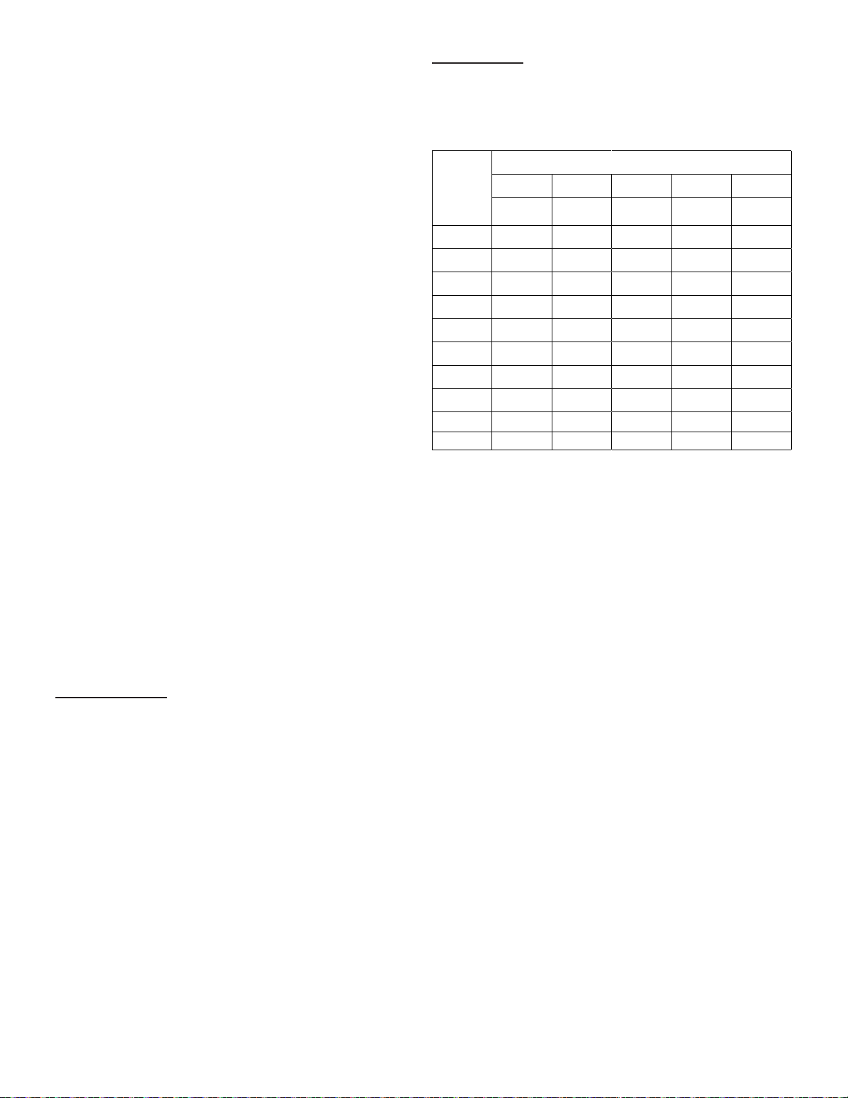
Table Method
The following table complies with ASHRAE Standard 62.2,
Table 4.1a, Continuous Whole-Building Ventilation rate in
cfm.
Table 8. Whole Building Ventilation Air Requirements
Number of Bedrooms
Floor Area 12345
(Square
Feet) cfm cfm cfm cfm cfm
<500 30 38 45 53 60
501 - 1000 45 53 60 68 75
1001 - 1500 60 68 75 83 90
1501 - 2000 75 83 90 98 105
2001- 2500 90 98 105 113 120
2501 - 3000 105 113 120 128 135
3001 - 3500 120 128 135 143 150
3501 - 4000 135 143 150 158 165
4001 - 4500 150 158 165 173 180
4501 - 5000 165 173 180 188 195
For more information about ASHRAE, go to:
https://www.ashrae.org.

17
THERMOSTAT VENTILATION PARAMETERS
Thermostat ventilation CFM parameters are to be adjusted
only after the HRV/ERV set up is completed and the CFMs
are known. Once the thermostat’s CFMs are adjusted they
are used with the thermostat’s timer algorithm to determine
how long to run the HRV/ERV and to change from low to
high speed if a 2-stage HRV/ERVs.
Go to menu > settings > advanced settings > view
dealer control center > equipment > smart hub. Locate
the parameters listed in “Table 9. Smart Hub Parameters
(Ventilation)”.
The following parameter will be application specic and are
only listed where applicable to the type of equipment and
control mode being used, for example, types of equipment
would be ERV or HRV and control mode would be either
Timed or ASHRAE.
Table 9. Smart Hub Parameters (Ventilation)
Parameter Description
Ventilation Control Mode - timed (default)
Ventilation Minutes
Per Hour
Parameter range is 0.0 - 60.0 minutes.
Default is 20.0 minutes. Can be adjusted in
increments of 1.0 minutes.
• The system rst tries to satisfy the ventilation
time by only ventilating while conditioning is
occurring. NOTE: Continuous fan is NOT
considered conditioning.
• When the required time remaining to
ventilate for the hour does not equals the
amount of time remaining in that hour, the
system begins ventilation and does not
stop until the ventilation time requirement
is satised.
• When ventilating without a conditioning
demand, the ventilation output is active as
well as a continuous indoor fan demand.
• When ventilating with a conditioning
demand, the ventilation output is active with
the conditioning demand outputs.
Ventilation Rates
Thermostat ventilation CFM parameters are to be adjusted only after the HRV/
ERV set up is completed and the CFMs are known. Once the thermostat’s
CFMs are adjusted they are used with the thermostat’s timer algorithm to
determine how long to run the HRV/ERV and to change from low to high speed
if a 2-stage HRV/ERVs.
Ventilation Rate Parameter range is 20 - 200 CFM. Default is
130 CFM. Can be adjusted in increments of
1.0 CFM.
Ventilation Rate for
Low Speed
Parameter range is 10 - 200 CFM. Default is
50 CFM. Can be adjusted in increments of
1.0 CFM.
Ventilation Rate for
High Speed
Parameter range is 20 - 500 CFM. Default is
130 CFM. Can be adjusted in increments of
1.0 CFM.
Table 9. Smart Hub Parameters (Ventilation)
Parameter Description
Ventilation
High Outdoor
Temperature Limit
Parameter range is 60 to 115ºF. Default is
100ºF. Can be adjusted in increments of
5ºF.
While the outdoor temperature is equal to or
higher than the setting for Ventilation High
Outdoor Temperature Limit, ventilation
does not run. When locked out due to high
outdoor temperature, it will become unlocked
when either the outdoor temperature is
missing, or when the temperature reported is
1°F less than the Ventilation High Outdoor
Temperature Limit setting when display units
are in Fahrenheit, or is reported as 0.5°C less
than lock out setting when the display units
are Celsius.
Ventilation
Low Outdoor
Temperature Limit
Parameter range is -20 to 55ºF. Default is 0ºF.
Can be adjusted in increments of 5ºF.
While the outdoor temperature is lower than
the setting for the Ventilation Low Outdoor
Temperature Limit, ventilation does not
run.
When locked out due to low outdoor tem-
perature, it will become unlocked when the
outdoor temperature is missing, or when the
temperature reported is 1°F higher than the
Ventilation Low Outdoor Temperature Lim-
it setting when display units are Fahrenheit,
or is reported as 0.5°C higher than lock out
setting when the display units are Celsius.
Ventilation High
Outdoor Dew Point
Limit
Parameter range is 45 to 80ºF. Default is
55ºF. Can be adjusted in increments of 5ºF.
While the outdoor dew point is higher than
the setting for the high outdoor dew point
limit, ventilation does not run.
When locked out due to high outdoor dew
point limit, it will become unlocked when the
outdoor dew point is missing, or when the
dew point temperature reported is 1°F less
than the lock-out setting when display units
are Fahrenheit, or is reported as 0.5°C less
than lock-out setting when the display units
are Celsius.
Ventilation Control Mode - ASHRAE
• In this mode the thermostat can assist the installer by validating
the ventilation CFMs are capable of meeting the ASHRAE required
ventilation volumes, but the thermostat has no ability to control CFM
from the HRV/ERV.
• The system rst tries to satisfy the ventilation volume by only
ventilating while conditioning is occurring. Continuous fan is not
considered conditioning.
• The total volume of ventilation air is accumulated and stored to
compare against the target hourly ventilation volume (Vhr). The
accumulated value resets each hour.
• When the remaining required volume of ventilation air for the hour
divided by the fan only ventilation rate is equal to or greater than
the time remaining to ventilate for the hour and no conditioning is
occurring, the system begins ventilation using continuous fan and
does not stop until the target hourly ventilation volume requirement
is satised.
• When ventilating without a conditioning demand, the ventilation
output is active as well a continuous indoor fan demand.
• When ventilating with a conditioning demand, the ventilation output is
active with the conditioning demand outputs.
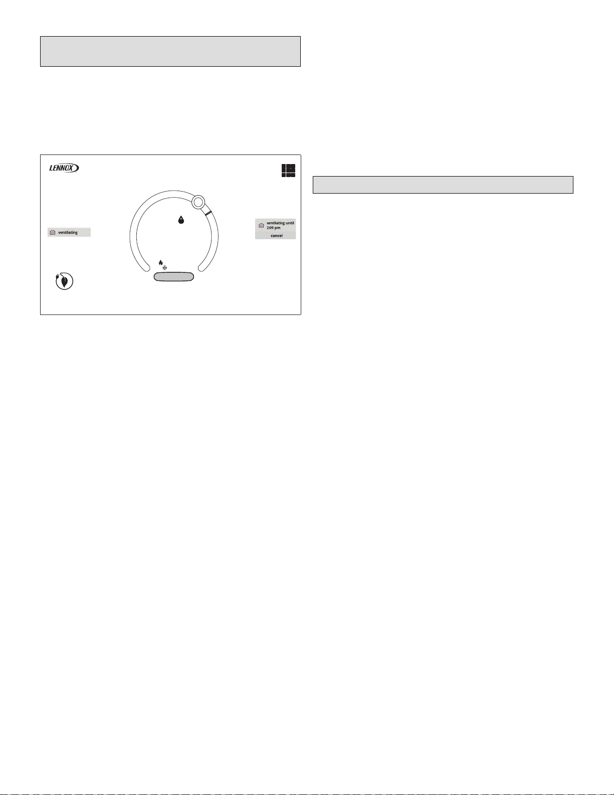
• When the system is ventilating, the user interface can indicate as
such by showing “ventilating” to the user on the home screen.
18
Table 9. Smart Hub Parameters (Ventilation)
Parameter Description
Ventilation Rates
Thermostat ventilation CFM parameters are to be adjusted only after the HRV/
ERV set up is completed and the CFMs are known. Once the thermostat’s
CFMs are adjusted they are used with the thermostat’s timer algorithm to
determine how long to run the HRV/ERV and to change from low to high speed
if a 2-stage HRV/ERVs.
Ventilation Rate Parameter range is 20 - 500 CFM. Default is
130 CFM. Can be adjusted in increments of
1.0 CFM.
Ventilation Rate for
Low Speed
Parameter range is 10 - 200 CFM. Default is
50 CFM. Can be adjusted in increments of
1.0 CFM.
Ventilation Rate for
High Speed
Parameter range is 20 - 500 CFM. Default is
130 CFM. Can be adjusted in increments of
1.0 CFM.
Ventilation Outdoor
Condition Override Options are Disabled (default) or Enabled.
ASHRAE
Compliance Check
= NO (Ventilation CFM too low to comply
with ASHRAE 62.2) or YES (Current settings
comply with ASHRAE 62.2)
ASHRAE Inltration
Credit
Parameter range is 0.0 - 200.0 CFM. Default
is 2500 square feet. Can be adjusted in incre-
ments of 1.0 CFM.
ASHRAE House
Floor Area Serviced
by This Ventilator
Parameter range is 500.0 - 5000.0 square
feet. Default is 2500.0 CFM. Can be adjusted
in increments of 100.0 square feet. The
formula for calculating how much ventilation
is required is:
(total square footage of the home/100) +
(number of bedrooms+1) x 7.5 cfm)
ASHRAE Number of
Bedrooms Parameter range is 1.0 - 10.0. Default is 3.0.
Can be adjusted in increments of 1.0.
Ventilation Outdoor Condition Override - Enabled
Ventilation
High Outdoor
Temperature Limit
Parameter range is 60 to 115ºF. Default is
100ºF. Can be adjusted in increments of
5ºF.
While the outdoor temperature is equal to or
higher than the setting for Ventilation High
Outdoor Temperature Limit, ventilation
does not run.
When locked out due to high outdoor tem-
perature, it will become unlocked when either
the outdoor temperature is missing, or when
the temperature reported is 1°F less than
the Ventilation High Outdoor Tempera-
ture Limit setting when display units are in
Fahrenheit, or is reported as 0.5°C less than
lock out setting when the display units are
Celsius.
Ventilation
Low Outdoor
Temperature Limit
Parameter range is -20 to 55ºF. Default is 0ºF.
Can be adjusted in increments of 5ºF.
While the outdoor temperature is lower than
the setting for the Ventilation Low Outdoor
Temperature Limit, ventilation does not
run.
When locked out due to low outdoor tempera-
ture, it will unlocked when the outdoor tem-
perature is missing, or when the temperature
reported is 1°F higher than the Ventilation
Low Outdoor Temperature Limit setting
when display units are Fahrenheit, or is
reported as 0.5°C higher than lock out setting
when the display units are Celsius.
Table 9. Smart Hub Parameters (Ventilation)
Parameter Description
Ventilation High
Outdoor Dew Point
Limit
Parameter range is 45 to 80ºF. Default is
55ºF. Can be adjusted in increments of 5ºF.
While the outdoor dew point is higher than
the setting for the high outdoor dew point
limit, ventilation does not run.
When locked out due to high outdoor dew
point limit, it will become unlocked when the
outdoor dew point is missing, or when the
dew point temperature reported is 1°F less
than the lock out setting when display units
are Fahrenheit, or is reported as 0.5°C less
than lock out setting when the display units
are Celsius.
19
iComfort E30 (15S63) or S30 (12U67)
Ventilation Control User Guide
VENTILATION HOME SCREEN ICONS
The ventilation icon that appears along the left side of the
home screen will appear when a pre-dened system level
routine for ventilation is running. The system level routine
was dened by your installer using the thermostats’ avail-
able parameter settings.
2:31 am
set−to
76
inside 57%
auto
away
0
modes /schedules
80
tue | Mar 31, 2015
Home
Figure 11. Ventilation Home Screen Notications
VENTILATION SETTINGS
Menu Selection
From the thermostat’s home screen, go to menu > settings
> ventilation. The ventilation menu option will only appear
if a ERV or HRV is installed and congured by your installer.
Any Lennox ERV or HRV reference in this instruction can
be congured as either a single or two-speed unit.
When selecting this menu option, selections will be either:
• Timed or ASHRAE (either Timed or ASHRAE is set by
your installer during setup of your thermostat).
• On (always).
• Off (always).
Factory default is ASHRAE. Your installer will need to
change it to Timed if that mode is desired.
User Demand Ventilation
You can also select “ventilate now” to start a ventilation
function immediately. Those menu options are 10, 20, 30,
40 and 50 minutes, 1 hour, 1-1/2 hours, 2 hours, 2-1/2 hours,
3 hours, 3-1/2 hours and 4 hours and custom. Custom will
allow a specic time to be set.
NOTE:Once ventilation is started, a notication appears
on the right-side of the home screen indicating a
time when that specic cycle will end and the option
to cancel the demand (see “Figure 11. Ventilation
Home Screen Notications”).
NOTE:Fan is running icon may also appear on the left-side
of the home screen when ventilation is running and
there is no cooling or heating demand active.
REMINDERS
From the thermostat home page, go to menu > settings >
reminders.
This screen allows you to set reminders as either disabled
or 3, 6, 12 or 24 months and also custom by specic date.
The other options on this screen is to trigger the reminder
event either by calendar or actual system run-time.
Reminders may be set for ventilation maintenance and
ventilation lter. Once a reminder is set for a specic item,
touch done to return to the previous screen. An “expires on
date” will appear next to the item just set.
How the Dehumidistat Works
When using either an H/C ERV/HRV Ventilation Push But-
ton Control (Y8249) or H/C ERV/HRV Deluxe Ventilation
Control (Y8250) a built-in dehumidistat is present. The fol-
lowing information is provided on how it works.
Highindoorhumiditylevels,duringtheheatingseason,have
become a problem in many well insulated, tight homes. Ex-
cessive condensation on the windows is a visual sign of
high indoor humidity levels. High indoor humidity levels can
result in mold, mildew and the eventual degradation of the
building structure itself. Your HRV reduces indoor humidity
levels when the outdoor air is drier than the indoor air.
These conditions usually occur during the heating season
when outdoor temperatures are less than 59°F (15°C) .
During the heating season, the operation of the HRV may
reduce indoor humidity levels sufciently to eliminate the
need for further dehumidication. Use the adjustable dehu-
midistat feature located on the main control if your home re-
quires further dehumidication during the heating season.
This feature aggressively addresses high indoor humidity
levels by initiating high speed ventilation when the indoor
humidity levels rise above the set point on the control. Once
the humidity in the house is reduced, the HRV will revert
back to its previous setting.
We suggest operating the HRV for the rst few days without
use of the Dehumidistat function to observe if a further de-
humidication effect will be required.
The dehumidistat operates in percentage of RH (relative
humidity) with 60 being high and 20 being low. If after a few
days, further dehumidication is required (the house is still
too humid), set the humidity level to a lower amount.
The average person is comfortable between 30% and 50%
RH. The Dehumidistat should be set to OFF for all seasons
except the heating season since a dehumidifying effect only
occurs when the outdoor air is dryer than the indoor air.
Dehumidistat Notes
Dehumidistat Disable automatically disables the dehu-
midistat function on the main control when outdoor tem-
peratures exceed 59°F (15°C) for a full 24 hour period. All
other HRV features and functions operate normally while
the Dehumidistat Function is disabled.
Dehumidistat Re-Enable automatically re-enables the de-
humidistat function when the outdoor temperature drops
below 59°F (15°C) for a full 24 hour period or if the HRV is
reset (unplugged for 30 seconds).
20
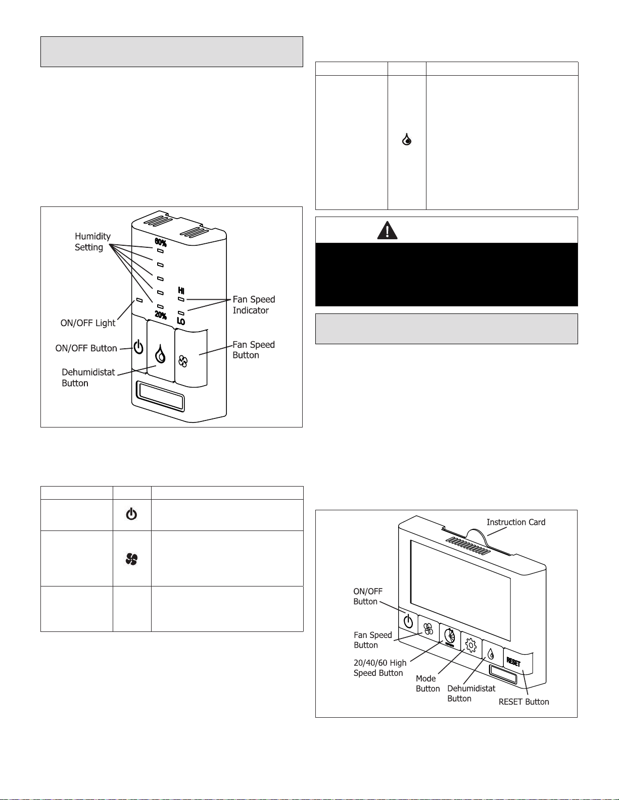
H/C ERV/HRV Ventilation Push Button
Control (Y8249)
The control offers the following features to control your
home’s ventilation.
• Two speed fan setting (LOW / HIGH)
• Standby setting (fan OFF)
• Electronic dehumidistat
• Compatible with wireless timers. Connect to 3-wire 20
gauge low voltage wire.
• Designed to be mounted in a standard 2 x 4” (51 x 102
mm) electrical box or surface mounted to a wall.
Figure 12. H/C ERV/HRV Ventilation Push Button
Control (Y8249)
Table 10. H/C ERV/HRV Ventilation Push Button
Control (Y8249) Settings
Settings Icon Description
Turning on the
Control Press and release the ON/OFF button. The
light above will illuminate.
Setting the
Ventilation Speed
Press and release the Fan button to select
LOW or HIGH fan speed. The corresponding
“Indicator Light” will illuminate. If both LO
and Hi indicator lights are off, the fan is OFF
but will turn ON if required by the Dehumidi-
stat or remote Timer (if installed).
Humidity Control
Your unit will reduce indoor humidity when
outdoor humidity levels are lower than
indoor humidity levels. This feature is only
effective when the outdoor temperature is
below 59˚F (15˚C).
Table 10. H/C ERV/HRV Ventilation Push Button
Control (Y8249) Settings
Settings Icon Description
Setting the
Dehumidistat
Press and release the Dehumidistat button
until the Dehumidistat Light is at the desired
setting. After a few seconds the Dehumid-
istat light will either ash or be on continu-
ous. A ashing light indicates the humidity
level is higher than the setting and the unit
is operating on high speed ventilation. A
continuous light indicates the humidity level
is lower than the setting. The Dehumidistat
will override the current speed setting to
HIGH speed. The Dehumidistat function
can be turned OFF by pressing the button
until no Dehumidistat light is on. Refer to
the “How the Dehumidistat Works” on page
19 section of this instruction for a detailed
description of Dehumidistat functionality.
IMPORTANT
Only one main control can be installed on the system.
Timers will not function when mode of operation is set
to “OFF”, unless specically installed for that function.
See “Main Control Standby Setting” on page 33 in this
instruction.
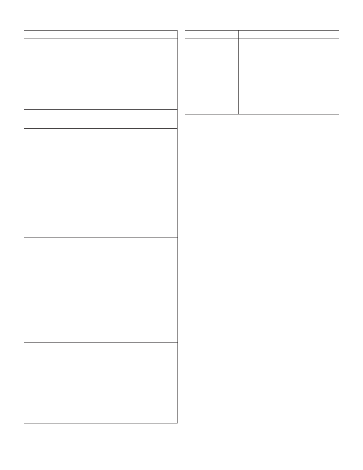
H/C ERV/HRV Deluxe Ventilation Control
(Y8250)
The control offers the most advanced features to control
your home’s ventilation.
• Five speed fan setting
• Standby setting (fan speed 0)
• Electronic dehumidistat
• 20/40/60 HIGH speed override button
• Compatible with H/C Ventilation Wireless Timer (Y8251)
• Easy to read back-lit LCD screen
• Slim-line design
• Connect to 3-wire 20 gauge low voltage wire
Figure 13. H/C ERV/HRV Deluxe Ventilation Control
(Y8250)
This manual suits for next models
17
Table of contents
Other Healthy Climate Solutions Fan manuals

Popular Fan manuals by other brands

Ventamatic
Ventamatic MaxxAir HVFF 20 Instruction & owner's manual

Sharper Image
Sharper Image AIRBAR AXIS 47 owner's guide

Home Decorators Collection
Home Decorators Collection CLERMONT Use and care guide

Be Cool
Be Cool BC78TU2002F manual

KUHL
KUHL Galaxis G8 user manual

Progress Lighting
Progress Lighting AirPro P2596 installation manual


